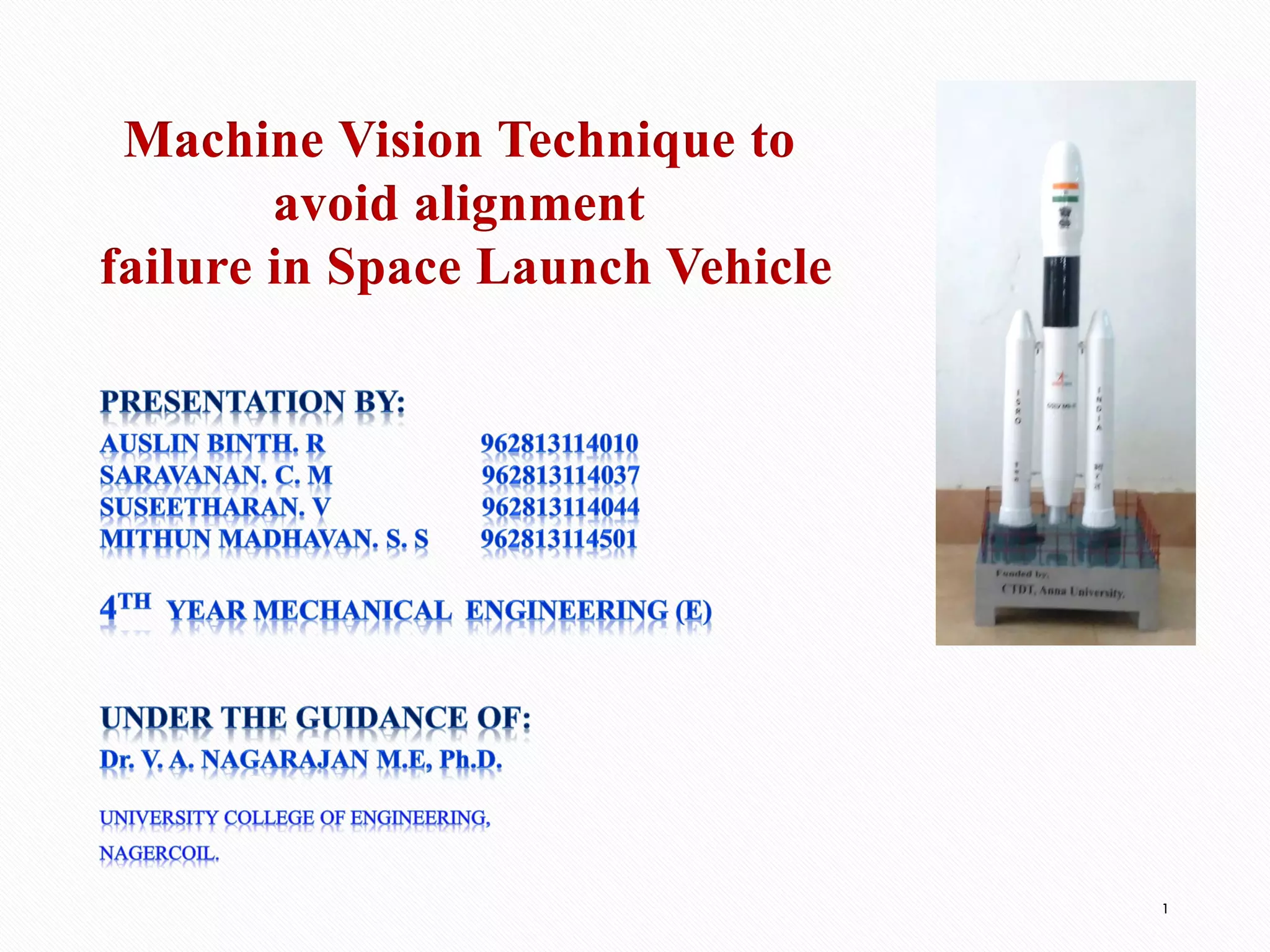
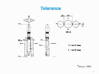
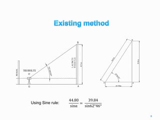
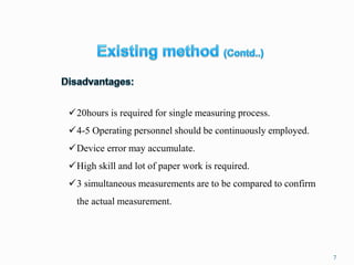
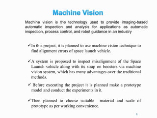
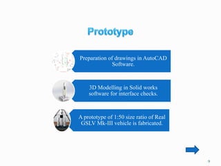
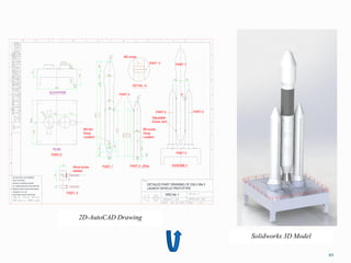
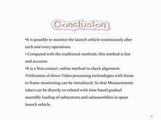
Machine Vision Technique to
avoid alignment
failure in Space Launch Vehicle
1
LAUNCH VEHICLES OF ISRO
Sounding Rocket
SLV-3
ASLV
PSLV
GSLV-MkII
GSLV-MkIII
2
*Source: ISRO
GSLV-Mk III
S 200 STRAP ON
MOTORS 200 tons of
propellant each.
(100s of burning time)
L110 STAGE
C25 STAGE
ENCAPSULATED
ASSEMBLY
PSLV
3
*Source: ISRO
4
Misalignment in pitch axis of & P+
strapon
(Front View)
Inclination in Yaw axis of P+
strapon
(Left Side view)
Axis offset of P+ strapon
(Top View)
5
*Source: ISRO
6
44.80
sinα
=
39.84
sin62°46°
Using Sine rule:
7
✓20hours is required for single measuring process.
✓4-5 Operating personnel should be continuously employed.
✓Device error may accumulate.
✓High skill and lot of paper work is required.
✓3 simultaneous measurements are to be compared to confirm
the actual measurement.
8
✓In this project, it is planned to use machine vision technique to
find alignment errors of space launch vehicle.
✓A system is proposed to inspect misalignment of the Space
Launch vehicle along with its strap on boosters via machine
vision system, which has many advantages over the traditional
methods.
✓ Before executing the project it is planned make a prototype
model and conduct the experiments in it.
✓Then planned to choose suitable material and scale of
prototype as per working convenience.
Machine vision is the technology used to provide imaging-based
automatic inspection and analysis for applications as automatic
inspection, process control, and robot guidance in an industry
9
Preparation of drawings in AutoCAD
Software.
3D Modelling in Solid works
software for interface checks.
A prototype of 1:50 size ratio of Real
GSLV Mk-III vehicle is fabricated.
M5 screw
Wood screw
welded
DETAIL- A
M5 Nut
fixing
Location
A
M5 screw
fixing
Location
PART- 4
PART- 4
1
PART-1
PART-3
DETAILED PART DRAWING OF GSLV Mk-3
LAUNCH VEHICLE PROTOTYPE
PART-3
PART-4
MACHINING FINISH IN MICRONS
ASSEMBLY
CHAMFER 1mm x 45°
REMOVE SHARP EDGES AND BURRS
Adjustable
Screw Joint
ALL DIMENSION ARE IN MILLIMETERS
UNLESS OTHERWISE SHOWN
PART-2- 2Nos.
PART-2
PART-1
DRG.No:
PLAN
ASK IF IN DOUBT
ELEVATION
PART-2
DO NOT SCALE THE DRAWING
10
2D-AutoCAD Drawing
Solidworks 3D Model
Test Setup Arrangement
Capturing the image
Image analysis
Result
11
12
13
RGB image
14
RGB to Grayscale converted image Grayscale to Binary converted image
15
•The initial pixel in higher contrast
difference region is selected to start
tracking the boundary.
• The selected pixel is compared
with neighbourhood pixels.
• If the grayscale value of one of
these eight pixels is higher than its
concentration, then that pixel
becomes the new boundary point.
•Then the traced boundary is
analysed
Boundary traced image
Boundary extracted image
16
17
18
*Picture Credits: www.isro.gov.in
19
*Picture Credits: www.isro.gov.in
•It is possible to monitor the launch vehicle continuously after
each and every operations.
• Compared with the traditional methods, this method is fast
and accurate.
•It is a Non contact, online method to check alignment.
•Utilization of direct Video processing technologies with frame
to frame monitoring can be introduced. So that Measurements
taken can be directly co-related with time based gradual
assembly loading of subsystems and subassemblies in space
launch vehicle.
20
21
REFERENCES
1. D. Vernon, Machine Vision – Automated Visual Inspection and Robot
Vision, Cambridge University Press, Cambridge, 1991.
2. F.T. Farago, M.A. Curtis, handbook of Dimensional Measurement, 3rd
Edition, Industrial Press Inc., 1994.
3. R. Lu, Study on the Visual Alignment Technique for On-line
Measurement, The Research Report of Postdoctoral Research. Tianjin
University, China, 2000.
4. RavishankarRao, “Future directions in industrial machine vision: a case
study of semiconductor manufacturing applications”, Image and Vision
Computing 14, 1993, 3-19.
5. About historic launchers and operational launchers by ISRO.
Launchers overview: http://www.isro.gov.in/launchers/
22
23

Machine vision technique to avoid alignment failure in space launch vehicle

  • 1.
    Machine Vision Techniqueto avoid alignment failure in Space Launch Vehicle 1
  • 2.
    LAUNCH VEHICLES OFISRO Sounding Rocket SLV-3 ASLV PSLV GSLV-MkII GSLV-MkIII 2 *Source: ISRO
  • 3.
    GSLV-Mk III S 200STRAP ON MOTORS 200 tons of propellant each. (100s of burning time) L110 STAGE C25 STAGE ENCAPSULATED ASSEMBLY PSLV 3 *Source: ISRO
  • 4.
    4 Misalignment in pitchaxis of & P+ strapon (Front View) Inclination in Yaw axis of P+ strapon (Left Side view) Axis offset of P+ strapon (Top View)
  • 5.
  • 6.
  • 7.
    7 ✓20hours is requiredfor single measuring process. ✓4-5 Operating personnel should be continuously employed. ✓Device error may accumulate. ✓High skill and lot of paper work is required. ✓3 simultaneous measurements are to be compared to confirm the actual measurement.
  • 8.
    8 ✓In this project,it is planned to use machine vision technique to find alignment errors of space launch vehicle. ✓A system is proposed to inspect misalignment of the Space Launch vehicle along with its strap on boosters via machine vision system, which has many advantages over the traditional methods. ✓ Before executing the project it is planned make a prototype model and conduct the experiments in it. ✓Then planned to choose suitable material and scale of prototype as per working convenience. Machine vision is the technology used to provide imaging-based automatic inspection and analysis for applications as automatic inspection, process control, and robot guidance in an industry
  • 9.
    9 Preparation of drawingsin AutoCAD Software. 3D Modelling in Solid works software for interface checks. A prototype of 1:50 size ratio of Real GSLV Mk-III vehicle is fabricated.
  • 10.
    M5 screw Wood screw welded DETAIL-A M5 Nut fixing Location A M5 screw fixing Location PART- 4 PART- 4 1 PART-1 PART-3 DETAILED PART DRAWING OF GSLV Mk-3 LAUNCH VEHICLE PROTOTYPE PART-3 PART-4 MACHINING FINISH IN MICRONS ASSEMBLY CHAMFER 1mm x 45° REMOVE SHARP EDGES AND BURRS Adjustable Screw Joint ALL DIMENSION ARE IN MILLIMETERS UNLESS OTHERWISE SHOWN PART-2- 2Nos. PART-2 PART-1 DRG.No: PLAN ASK IF IN DOUBT ELEVATION PART-2 DO NOT SCALE THE DRAWING 10 2D-AutoCAD Drawing Solidworks 3D Model
  • 11.
    Test Setup Arrangement Capturingthe image Image analysis Result 11
  • 12.
  • 13.
  • 14.
    14 RGB to Grayscaleconverted image Grayscale to Binary converted image
  • 15.
    15 •The initial pixelin higher contrast difference region is selected to start tracking the boundary. • The selected pixel is compared with neighbourhood pixels. • If the grayscale value of one of these eight pixels is higher than its concentration, then that pixel becomes the new boundary point. •Then the traced boundary is analysed Boundary traced image Boundary extracted image
  • 16.
  • 17.
  • 18.
  • 19.
  • 20.
    •It is possibleto monitor the launch vehicle continuously after each and every operations. • Compared with the traditional methods, this method is fast and accurate. •It is a Non contact, online method to check alignment. •Utilization of direct Video processing technologies with frame to frame monitoring can be introduced. So that Measurements taken can be directly co-related with time based gradual assembly loading of subsystems and subassemblies in space launch vehicle. 20
  • 21.
    21 REFERENCES 1. D. Vernon,Machine Vision – Automated Visual Inspection and Robot Vision, Cambridge University Press, Cambridge, 1991. 2. F.T. Farago, M.A. Curtis, handbook of Dimensional Measurement, 3rd Edition, Industrial Press Inc., 1994. 3. R. Lu, Study on the Visual Alignment Technique for On-line Measurement, The Research Report of Postdoctoral Research. Tianjin University, China, 2000. 4. RavishankarRao, “Future directions in industrial machine vision: a case study of semiconductor manufacturing applications”, Image and Vision Computing 14, 1993, 3-19. 5. About historic launchers and operational launchers by ISRO. Launchers overview: http://www.isro.gov.in/launchers/
  • 22.
  • 23.