Downloaded 12 times
![C.Vinil Babu Int. Journal of Engineering Research and Applications www.ijera.com
ISSN : 2248-9622, Vol. 4, Issue 9( Version 5), September 2014, pp.75-80
www.ijera.com 75 | P a g e
Behaviour of M30 Grade concrete with confinement under axial compression C.Vinil Babu*, V.K.Visweswara Rao** *(M.Tech Student, Department of Civil Engineering, G.Pulla Reddy Engineering College, Kurnool, A.P)
** (Assistant Professor, Department of Civil Engineering, G.Pulla Reddy Engineering College, Kurnool,A.P) ABSTRACT The strength and durability of concrete have undergone continuous improvement. Over the years and these improved materials are now commonly used. In the present experimental investigation the behaviour of M30 grade concrete with and without confinement for different percentages of replacement of silica fume is studied under axial compression as per IS mix design. The 150mm x 300mm cylindrical specimens were cast with and without confinement and investigating the mechanical properties like axial compressive strength and stress – strain behaviour. It was observed that the confinement of concrete has increased the 28days strength for different percentages of confinement and that the peak stress and corresponding strain at peak stress increased with increase in percentages of confinement Keywords – Axial compression strength, confinement, cylinders, Silica fume, stress-strain behaviour,
I. Introduction
It is generally accepted that plain concrete exhibits a brittle failure when it is compressed, which leads to a rapid loss of load-carrying capacity. The concept of using confinement reinforcement is to restrain the concrete from expansion and thus prolongates the failure[4].[5] The strength and durability of concrete has undergone continuous improvement over the years and these improved materials are now commonly used. The strength of concrete is influenced by the methods of concrete with time and region. In the past, a lot of research has focused on using steel spirals and rings to confine concrete (Ahmad and Shah 1982, El-Dash and Ahmad 1995, and Mander et al 1988). The increase in ductility and strength were prominent. With the advent of composite materials, replacement of steel by confinement seems to be a rational method to solve the corrosion problems. In addition, due to the difference in the stress-strain behaviour of steel, the induced confining pressure is also different when subjected to compression. The stress of steel remains virtually constant after its yield point so the induced pressure cannot increase after yielding. On the other hand, confinement concrete possesses linear elastic properties. The stress of the confinement keeps on increasing with strain, and thus a monotonically increasing confining pressure is produced. The maximum confining pressure is obtained when the ultimate strength of the confinement is reached. When further load is applied, failure of the confined concrete often occurs as a result of fracture of the confinement reinforcement.
Today, high strength concrete is used in off- shore platforms, sea structures, high-rise buildings and bridges. One of the advantages of using moderate strength to high strength concrete in columns is to reduce the cross section. It was found that using high strength concrete in multi-storey, high-rise buildings is economical. However, using high strength concrete in building columns in seismic areas poses some problems. The high strength concrete has less ductility compared to ordinary concrete[5]. In order to verify this, an experimental programme was carried out and the results are described in this paper.
II. Materials Used And Properties
2.1. Cement The Ultra-Tech 53 grade Ordinary Portland Cement (OPC) which conforms to IS 12269-1987, is used in the present study 2.2. Silica Fume The silica fume Astrra Chemical Ltd. Chennai which complies with ASTMC 1240 and IS15388- 2003 is used in the study. It is in white powder form which contains laterently reactive silicon-dioxide and no chloride or other potentially corrosive substance. 2.3. Aggregates
The fine and coarse aggregates occupy about 60– 75 per cent of the concrete volume (70–85% by mass) and hence strongly influence the properties of fresh as well as hardened concrete, its mixture proportions, and the economy. Aggregates used in concrete should comply with the requirement.
RESEARCH ARTICLE OPEN ACCESS](https://image.slidesharecdn.com/m49057580-141021035308-conversion-gate02/85/Behaviour-of-M30-Grade-concrete-with-confinement-under-axial-compression-1-320.jpg)
![C.Vinil Babu Int. Journal of Engineering Research and Applications www.ijera.com
ISSN : 2248-9622, Vol. 4, Issue 9( Version 5), September 2014, pp.75-80
www.ijera.com 75 | P a g e
Behaviour of M30 Grade concrete with confinement under axial compression C.Vinil Babu*, V.K.Visweswara Rao** *(M.Tech Student, Department of Civil Engineering, G.Pulla Reddy Engineering College, Kurnool, A.P)
** (Assistant Professor, Department of Civil Engineering, G.Pulla Reddy Engineering College, Kurnool,A.P) ABSTRACT The strength and durability of concrete have undergone continuous improvement. Over the years and these improved materials are now commonly used. In the present experimental investigation the behaviour of M30 grade concrete with and without confinement for different percentages of replacement of silica fume is studied under axial compression as per IS mix design. The 150mm x 300mm cylindrical specimens were cast with and without confinement and investigating the mechanical properties like axial compressive strength and stress – strain behaviour. It was observed that the confinement of concrete has increased the 28days strength for different percentages of confinement and that the peak stress and corresponding strain at peak stress increased with increase in percentages of confinement Keywords – Axial compression strength, confinement, cylinders, Silica fume, stress-strain behaviour,
I. Introduction
It is generally accepted that plain concrete exhibits a brittle failure when it is compressed, which leads to a rapid loss of load-carrying capacity. The concept of using confinement reinforcement is to restrain the concrete from expansion and thus prolongates the failure[4].[5] The strength and durability of concrete has undergone continuous improvement over the years and these improved materials are now commonly used. The strength of concrete is influenced by the methods of concrete with time and region. In the past, a lot of research has focused on using steel spirals and rings to confine concrete (Ahmad and Shah 1982, El-Dash and Ahmad 1995, and Mander et al 1988). The increase in ductility and strength were prominent. With the advent of composite materials, replacement of steel by confinement seems to be a rational method to solve the corrosion problems. In addition, due to the difference in the stress-strain behaviour of steel, the induced confining pressure is also different when subjected to compression. The stress of steel remains virtually constant after its yield point so the induced pressure cannot increase after yielding. On the other hand, confinement concrete possesses linear elastic properties. The stress of the confinement keeps on increasing with strain, and thus a monotonically increasing confining pressure is produced. The maximum confining pressure is obtained when the ultimate strength of the confinement is reached. When further load is applied, failure of the confined concrete often occurs as a result of fracture of the confinement reinforcement.
Today, high strength concrete is used in off- shore platforms, sea structures, high-rise buildings and bridges. One of the advantages of using moderate strength to high strength concrete in columns is to reduce the cross section. It was found that using high strength concrete in multi-storey, high-rise buildings is economical. However, using high strength concrete in building columns in seismic areas poses some problems. The high strength concrete has less ductility compared to ordinary concrete[5]. In order to verify this, an experimental programme was carried out and the results are described in this paper.
II. Materials Used And Properties
2.1. Cement The Ultra-Tech 53 grade Ordinary Portland Cement (OPC) which conforms to IS 12269-1987, is used in the present study 2.2. Silica Fume The silica fume Astrra Chemical Ltd. Chennai which complies with ASTMC 1240 and IS15388- 2003 is used in the study. It is in white powder form which contains laterently reactive silicon-dioxide and no chloride or other potentially corrosive substance. 2.3. Aggregates
The fine and coarse aggregates occupy about 60– 75 per cent of the concrete volume (70–85% by mass) and hence strongly influence the properties of fresh as well as hardened concrete, its mixture proportions, and the economy. Aggregates used in concrete should comply with the requirement.
RESEARCH ARTICLE OPEN ACCESS](https://image.slidesharecdn.com/m49057580-141021035308-conversion-gate02/75/Behaviour-of-M30-Grade-concrete-with-confinement-under-axial-compression-1-2048.jpg)
![C.Vinil Babu Int. Journal of Engineering Research and Applications www.ijera.com
ISSN : 2248-9622, Vol. 4, Issue 9( Version 5), September 2014, pp.75-80
www.ijera.com 79 | P a g e
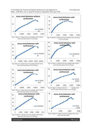
Fig 15:Stress vs. Strain Curve for cylinder with 1.22% steel With SF 10%
Fig 16:Stress vs. Strain Curve for cylinder with 1.22% steel with silica fume 15% at 28 days
Fig 17: Comparison of Stress vs. Strain graphs of cylinders with different Confinements and different percentages of silica fume at 28 days
Fig 18: Comparison of normalized Stress vs. Strain graphs of cylinders with different confinements at 28 days
V. CONCLUSIONS:
Studies have been carried out on behavior of M30 grade concrete with and without confinement under axial compression. The parameters studied include compressive strength, flexural strength test and comparison of stress-strain calculations of concrete with and without confinement. And also tests are conducted on concrete by partially replacement of cement by silica fume. Based on the study conducted the following conclusions are drawn.
1. Percentage of Confinement increases the strength of concrete also increased the strengths at 28 days.
2. Compression strength also increased by partial replacement of cement with silica fume and also with and without confinement.
3. Cement replacement up to 10% silica fume leads to increase in compressive strength of concrete. Beyond 10 %there is a decrease in compressive strength of concrete.
4. An increase in volume of confinement improves the ductility factor of confined concrete.
5. The ductility i.e. the ratio of the strain at peak stress of confined concrete to the strain at peak stress of corresponding unconfined concrete.
REFERENCES [1]. C.RAJAMALLU,A.BALAJI Rao, Behaviour Of Self Compacting Concrete Under Axial Compression With And Without Confinement (ISSN: 2348-4748,Volume 1,ISSUE 3,March 2014) [2]. NRD Murthy, Ramaseshu D, Rao MVS. “ Constitutive Behaviour Of Fly Ash Concrete With Steel Fibers In Ordinary Grade, IE(Institute Of Engineers) Journal”- Vol,88(2007) 41-46.
0
20
40
60
0
0.002
0.004
0.006
0.008
stress-strain behaviour with confinement
SF10% 1.2208
0
10
20
30
40
50
-0.002
0
0.002
0.004
0.006
0.008
0.01
stress-strain behaviour
0
0.5
1
1.5
-0.5
0
0.5
1
1.5
Normalized Stress-strain
0
20
40
0
0.001
0.002
0.003
0.004
stress-strain behaviour with confinement
SF15% 1.2208](https://image.slidesharecdn.com/m49057580-141021035308-conversion-gate02/85/Behaviour-of-M30-Grade-concrete-with-confinement-under-axial-compression-5-320.jpg)
![C.Vinil Babu Int. Journal of Engineering Research and Applications www.ijera.com
ISSN : 2248-9622, Vol. 4, Issue 9( Version 5), September 2014, pp.75-80
www.ijera.com 80 | P a g e
[3]. Dr.M.V.Seshagiri Rao “ Self Compacting High Performance Concrete”,JNTUCE, Hyderabad. [4]. H.Y.Leung And C.J.Burgoyne Compressive Behaviour Of Concrete Confined By Aramid Fiber Spirals [5]. Metin Husem and selim pul investigation of stress-strain model for confined high strength concrete [6] T.Suresh Babu ,M.V.Seshagiri Rao And D.Rama Seshu Mechanical Properties And Stress-Strain Behaviour Of Self Compacting Concrete With And Without Glass Fibers Asian Journal Of Civil Engineering VOL.9,NO.5(2008) Pg 457-472 [7]. Marwan N.Youssef,Maria Q.Feng And Ayman S.Stress-Strain Model For Concrete Confined By FRP Composites Engineering Volume 38, Issues 5-6,July-September 2007, And Pages 614-628 [8]. J.B.Mander ,M.J.N.Prisestley And R.Park , Fellow. ASCE Observed Stress-Strain Behaviour Of Confined Concrete [9]. R.Abbasnia ,A.Holakoo ,An Investigation Of Stress-Strain Behaviour Of FRP Confined Concrete Under Cyclic Compressive Loading [10]. T.Shanmugapriya2,Dr.R.N.Uma Experimental Investigation On Silica Fume Aspartial Replacement Of Cement In High Performance Concrete [11]. L.Lam And J.G.Teng Stress-Strain Model For FRP –Confined Concrete Under Cyclic Axial Compression Engineering Structures Volume 31, Issue 2, February 2009, Pages 308-321. [12]. IS12269-1987(Reaffirmed 1999),Specification For 53 Grade Ordinary Portland Cement,1st Reprint, September 1993. [13]. IS 2386-1963, Method Of Tests For Aggregates For Cement. {14]. IS 456-2000, Indian Standard Plain And Reinforced Concrete-Code Of Practice,4th Revision, 1st Reprint, September 2000.](https://image.slidesharecdn.com/m49057580-141021035308-conversion-gate02/85/Behaviour-of-M30-Grade-concrete-with-confinement-under-axial-compression-6-320.jpg)

This document discusses the experimental investigation of M30 grade concrete behavior under axial compression with confinement and varying percentages of silica fume replacement. It finds that confinement enhances concrete strength and ductility, while replacing cement with up to 10% silica fume improves compressive strength, beyond which strength decreases. The study concludes that increased confinement volume and partial silica fume replacement positively affect concrete properties.


![Pl 588 11 - gestão democrática[1]](https://cdn.slidesharecdn.com/ss_thumbnails/pl588-11-gestodemocrtica1-111014135741-phpapp02-thumbnail.jpg?width=640&height=640&fit=bounds)


