Your colleague changed the MSC timers T305 and T308 to clear calls early before BSS drop statistics could be recorded. However, this does not actually improve network quality and may mask underlying RF interference issues. T305 and T308 should be set to at least 11 seconds to allow the related BSS timers like T200*(N200+1) to expire first at the air interface, ensuring successful message transmission. Playing with timers does not solve problems and can mislead operators into thinking quality is better than it is.
T200 and N200 are timers related to the LAPD protocol used for communication between the BTS and MS. T200 is started when a frame is transmitted and defines the time between retransmissions if an acknowledgment is not received. The frame will be retransmitted up to N200 times before a link failure is detected. If the T200 timer expires after N200 retransmissions without an acknowledgment, the connection will be dropped due to a data link failure between the BTS and MS. Setting the T200 and N200 values too low can cause increased call drops, while too high may cause unnecessary retransmissions.
This document describes various timers used on the network side in GSM. It lists the timer name, description of what each timer is used for, and typical values. Many of the timers are used to keep radio resources allocated for a period of time while waiting for a mobile station to respond to a message or successfully access a channel. The values range from 50ms to several seconds and are set by the network to allow enough time for procedures while avoiding keeping resources allocated indefinitely if the mobile station fails to respond.
The document describes various timers used on the network side and mobile station side in GSM networks. It lists the purpose and value of timers like T3101, T3103, T3105, T3107 that are used on the network side for functions like channel allocation, handover, physical information messaging. It also lists timers like T3122, T3124, T3126, T3128, T3130 on the mobile station side for random access, uplink investigation, cell change procedures. The timer values are set by the network and depend on factors like channel type and maximum transmission times.
This document discusses cell parameters in GSM networks. It explains that cell parameters contain important information used by mobile devices to access the network, perform cell selection and reselection, and cooperate with the network. It describes several key cell parameters, including location area code (LAC), cell identity (CI), base station identity code (BSIC), and common control channel configuration (CCCH Conf). The goal of these parameters is to uniquely identify cells and networks, enable location services, and optimize signaling load through proper configuration of common channels.
This document discusses call drop troubleshooting and measurement. It defines call drop counters and their relationships, providing definitions and increment logic. Key points of measurement are identified. Common causes of call drops are analyzed, including parameter, path balance, coverage gap, quality/interference, and missing neighbor problems. Troubleshooting steps are outlined for various problem types.
Day1 slot3 br radio configuration assessment and bss radio configurationv0.4fdr1975
The document discusses radio configuration assessment and planning for both a Broadband Radio (BR) system and a Base Station Subsystem (BSS). It provides examples of configuration settings for signaling allocation, traffic channel allocation, and packet switched capacity for a cell with either 8 or 10 TRXs. Key parameters for both the BR and BSS configurations are also defined.
This document describes the process of optimizing GSM900/1800 mobile networks. Key metrics are monitored daily, weekly, and monthly to check network health using a tool called Optima. Daily counters include call setup success rate, dropped calls, handover failures, and congestion. Issues like low call success rates could be due to problems like SDCCH congestion, phantom RACHs, CM service rejects, or TCH failures. Weekly and monthly statistics provide further insight into trends, retention, accessibility, load, and overall performance. Reports evaluate capacity and optimization progress.
This document discusses a case study of call drops occurring in the second sector of base station C. Through analyzing traffic statistics and conducting drive tests, it was found that interference was the cause of the high call drop rate. Specifically, a broadband repeater transmitting nearby digital signals was amplifying interference into the sector. Lowering the power of the repeater resolved the call drop issue.
This document discusses cell selection and reselection in GSM networks. It explains:
1) Cell selection is performed when a mobile first turns on to select an initial "camped-on" cell. Reselection occurs when the mobile moves to ensure it remains on the best cell.
2) C1 and C2 criteria are used for selection and reselection. C1 compares signal levels and C2 adds offsets.
3) In the scenario, the mobile selects the 900MHz cell using C1/C2 criteria. To prefer the 1800MHz cell instead, the document suggests using the C2 formula without offsets by setting the penalty time lower.
The document provides an overview, definitions, and recommended formulas for calculating the TCH call drop rate KPI. It describes the key signaling procedures and measurement points for analyzing call drops. Furthermore, it discusses nine major factors that can affect the TCH call drop rate, such as hardware failures, transmission problems, parameter settings, interference, coverage issues, and antenna system problems. The document also provides solutions and case studies for optimizing the TCH call drop rate.
The document provides guidance on optimizing the TCH congestion rate KPI in GSM networks. It defines TCH congestion rate, discusses its impacts, and identifies potential influencing factors including network capacity, faults, interference, parameter settings, third-party devices, and software versions. The document then outlines an analysis procedure and provides optimization methods addressing each influencing factor, such as traffic balancing, hardware troubleshooting, interference reduction, parameter tuning, and capacity expansion. Example cases are also presented.
1. The document analyzes key performance indicators related to SDCCH establishment success rates in an AFC radio network, which have been observed to be low at 89%.
2. A main cause identified for the low SDCCH establishment is timer T3101 expiration after sending Immediate Assignment messages, indicating 11% failure due to no response from mobile stations. This could be due to "phantom" random access bursts or abnormal mobile station behavior.
3. Other potential contributing factors discussed include periodic registration interval being too short, location area border cells, cell broadcast usage, and low signal strength, but clear relationships between these and SDCCH establishment success rates were not found based on the investigation. The document outlines further
The document describes the call flow procedures for mobile originating and mobile terminating calls in a GSM network.
For a mobile originating call, the MS requests a dedicated channel and indicates it wants to set up a call. The MSC receives the call setup message and checks for call barring before establishing a link with the BSC. The BSC assigns a traffic channel for the call.
For a mobile terminating call, the call is routed to the GMSC serving the called subscriber's home network. The GMSC queries the HLR for routing information. The HLR provides a roaming number to route the call to the subscriber's current MSC. The MSC pages the subscriber through the BSCs in their
This document discusses selecting the appropriate capacity for a Base Station Controller (BSC) in a mobile telecommunications network. It provides the following guidelines:
1. Allow a 20% margin for additional TRXs and space for future upgrading. Minimize handovers between BSCs.
2. Calculate required capacity based on offered traffic plus a 10% margin, not installed capacity.
3. Use Erlang B calculations to determine the number of channels needed to support the traffic load at a 0.1% blocking rate.
4. Divide the number of required channels by the number supported per Ater link or interface to determine the number of links needed between the BSC and core network.
This document discusses GSM network SDCCH congestion and potential solutions. It begins by describing the signaling flow for SDCCH seizure and release. It then defines an indicator for SDCCH congestion as the percentage of signaling channel blocking times out of total attempts. The document classifies causes of SDCCH congestion, provides procedures for checking SD congestion, and describes typical cases including congestion due to LAPD delay from transmission faults, large quantity of location updates from cross-LAC coverage, strong interference, location updates from HLR cutover, and short message pagers.
The document discusses SDCCH (Standalone Dedicated Control Channel) configuration and usage in GSM networks. It describes possible SDCCH configurations including SDCCH/8 and SDCCH/4. It also discusses SDCCH holding times for different functions, reasons for SDCCH congestion, and methods to prevent congestion through proper dimensioning of SDCCH resources.
Introduction
Channel Configuration
Idle Mode Operation
Protocols
Radio resources
Measurements
Power Control
HO process
Intelligent Underlay Overlay
Handover Support for Coverage Enhanchements
The extended cell
Dynamic Hotspot
Dual band GSM/DCS Network Operation
Half Rate
HSCSD
This document provides guidelines for analyzing problems in a mobile network. It presents decision trees and flowcharts to help troubleshoot issues related to call setup success rate, SDCCH assignment, SDCCH congestion, TCH call drop, TCH seizure failure rate, TCH blocking rate, abnormal traffic patterns, idle interference, outgoing handover failure rate, and incoming handover failure rate. Potential causes are identified at each step to direct further investigation and resolution of issues.
Channel failure rate above defined thresholdaabaap
The document discusses troubleshooting channel failure rate alarms on 2G NSN networks. It provides details on what the alarm means, including supplementary information fields to identify the faulty channel. It recommends finding the cause of alarms by checking channel release messages and restoring channels by locking and unlocking them. Parameters affecting the alarm are listed, and it is noted the alarm will automatically cancel after the measurement period if the situation is resolved without actions. Responses suggest checking the Abis allocation between BTS and BSC, performing hardware replacements, and conducting a sector reset as initial steps to resolve the issue.
The document discusses various logical channels used in GSM networks such as broadcast control channel (BCCH), common control channels (CCCH), dedicated control channels (DCCH), and traffic channels (TCH). It describes the purpose and usage of different channel types including stand-alone dedicated control channel (SDCCH), slow associated control channel (SACCH), and fast associated control channel (FACCH). The document also covers topics like burst structure, mapping of logical channels to physical channels, and usage of SDCCH in GSM networks.
The document discusses GSM-GPRS channel configuration and dimensioning. It covers:
1. Channel configuration options including combined, non-combined, and hybrid configurations and how logical channels are mapped to timeslots.
2. Signaling channel (SDCCH) dimensioning based on call setup load and location update load to determine the number of subscribers that can be supported.
3. Common control channel (CCCH) load calculation including RACH, PCH, and AGCH capacities and how they are used to page mobiles and grant channel access.
There are several ways to improve TBF Drop rates mentioned in the document:
1. Check frequency usage and retransmission rates to identify potential frequency issues and improve carrier to interference ratios to reduce interference.
2. Use the transmitter with the best broadcast control channel for packet data channels.
3. Ensure GPRS link adaptation is enabled and limit coding schemes to the more robust MCS7 if frequency changes don't help.
4. Reduce the number of users per packet data channel and check packet control unit congestion and utilization.
1. The document discusses various coverage enhancement features used in cellular networks including extended cell range, long reach timeslots, super extended cells, and smart radio concepts.
2. It provides details on the technical implementation of these features such as delayed receivers, double BCCH allocation lists, and parameters for handover control.
3. Advanced concepts like intelligent downlink diversity, interference rejection combining, and space time interference rejection combining are introduced to further improve coverage and capacity.
SDCCH definition, understanding, and troubleshooting.
What is the SDCCHs blocking rate?
The sdcch_blocking_rate statistic tracks the percentage of attempts to allocate an sdcch that were blocked due to no available sdcch resources
This document describes events generated by TEMS products related to GSM, WCDMA, LTE, and TD-SCDMA networks. It includes a list of over 50 events with descriptions and notes on when they are generated. Example events include call establishment, cell reselection, handover failures, and data service events. The document also provides overviews of selected event families and details on call events and their state machines.
The document discusses timing advances in GSM networks. It explains that timing advances are used to compensate for propagation delay between mobile stations and base transceiver stations. The base station system determines the timing advance needed based on how far away it perceives the mobile station to be. Each timing advance corresponds to a range of distances, with each subsequent timing advance representing an additional 553.5 meters in distance from the base transceiver station. The maximum distance of a cell is standardized at 37.8 kilometers to account for the round trip delay of the radio signal.
This document summarizes the key principles of GSM frequency band allocation and multiple access technology. It discusses that GSM uses both FDMA and TDMA, with frequency bands divided into 200 kHz carriers and time divided into timeslots. The basic transmission unit in GSM is a burst, which is transmitted within a slot over a carrier. Different burst types carry different information for functions like access, synchronization, and data transmission.
Call Setup Success Rate Definition and Troubleshooting Assim Mubder
The CSSR indicates the probability of successful calls initiated by the MS. The CSSR is an important KPI for evaluating the network performance. If this KPI is too low, the subscribers are not likely to make calls successfully. The user experience is thus affected.
Parameter check list for tch drop in huawei system 2 - blogs - telecom sourceEfosa Aigbe
The document discusses 15 parameters that can affect TCH (Traffic Channel) call drop rates in Huawei mobile networks. It provides details on how adjusting each parameter can help reduce call drops by optimizing handovers, access procedures, radio link monitoring thresholds and timers. The parameters control functions like cell reselection, handover triggers, channel assignment and call clearing procedures. Fine-tuning these parameters based on traffic measurements can help minimize call drops due to issues like poor radio conditions, interference or timing out of processes.
This document discusses various causes and troubleshooting steps related to 2G call drops and unsuccessful handovers. It addresses issues like low signal strength, interference, incorrect parameter settings, transmission faults, hardware faults, and more. The key performance indicators of TCH Drop Rate and Handover Failure Rate are defined. Causes of dropped calls on traffic channels include excessive timing advance, low signal strength, poor quality, sudden loss of connection, and other factors. Investigation steps provided include checking error logs, parameters, neighboring cell definitions, transmission quality, antenna installation, and more.
1. The document discusses reasons for dropped calls on traffic channels (TCH) and stand-alone dedicated control channels (SDCCH) in GSM networks.
2. It outlines five main reasons for TCH drops - excessive timing advance, low signal strength, poor quality, sudden loss of connection, and other reasons. Corrective actions and solutions are provided for each reason.
3. For SDCCH drops, the key reasons listed are low signal strength, poor quality, too high timing advance, mobile errors, subscriber behavior, battery flaws, and TCH congestion. Troubleshooting steps and solutions are also provided.
The document discusses key performance indicators (KPIs) for cellular networks and provides relationships between network components and their capacities. It also analyzes reasons for call blocking, dropping, and failures during call setup and solutions to address them, including parameter tuning, hardware checks, interference mitigation, and useful reports.
This document discusses key performance indicators (KPIs) for mobile networks and reasons for and solutions to poor KPI values. It provides information on relationships between network elements, monitored KPIs like service drop blocking and call drop rates, reasons for poor values such as hardware issues and interference, and solutions like parameter tuning and adding network capacity. Specific KPIs covered include service drop blocking, service drop, traffic channel blocking, traffic channel assignment, traffic channel drop, and handover success rate.
This document discusses key performance indicators (KPIs) for monitoring a GSM network and reasons for and solutions to common issues. It provides relationships between network elements, defines terms like SD blocking and dropping, TCH blocking and assignment, and TCH dropping. Causes of and fixes for these issues are outlined, such as adjusting parameters, adding TRXs, improving hardware, and tuning neighbors. Reports for analyzing each issue are also listed.
The document discusses key performance indicators (KPIs) for monitoring a GSM network, including reasons for and solutions to issues like SD blocking, SD drop, TCH blocking, TCH assignment failure, and TCH drop. It provides technical details on the relationships between network elements like BSCs, BTSs, TRXs, and timeslots. It also lists common causes of the issues like hardware faults, interference, parameter misconfiguration, and outlines steps to troubleshoot and resolve problems.
This document discusses key performance indicators (KPIs) for mobile networks and reasons for and solutions to common issues. It provides relationships between network elements, definitions of terms like SDCCH and reasons for service degradation issues like SD blocking, SD drop, TCH blocking, poor TCH assignment and TCH drop. Solutions provided include parameter tuning, adding resources, hardware checks, neighbor planning and drive testing. Reports to monitor each issue are also listed.
This document discusses key performance indicators (KPIs) for mobile network analysis. It provides information on relationships between network elements, reasons for poor KPI values like service drop blocking and dropping, and potential solutions. KPIs to monitor include service drop blocking, service drop, traffic channel blocking, traffic channel assignment, traffic channel drop, and handover success rate. Causes of issues include hardware problems, interference, parameter misconfiguration, and overlapping coverage. Solutions involve checking configurations, drive testing, adding resources, retuning parameters, and resolving hardware faults.
Nokia gsm-kpi-analysis-based-on-daily-monitoring-basis-presentationmohammed khairy
This document discusses key performance indicators (KPIs) for monitoring a GSM network and reasons for and solutions to common issues. It provides relationships between different network elements and describes concepts like SD blocking, SD drop, TCH blocking, TCH assignment, TCH drop, and handover success rate (HOSR). For each KPI, it outlines potential causes for degradation and recommendations to address hardware faults, interference, parameter misconfiguration, and other problems.
The document discusses various 2G KPIs including:
- TCH drop rate which measures abnormal call drops on traffic channels
- SDCCH drop rate which measures call drops on standing dedicated control channels
- TCH congestion/blocking which measures rejected traffic channel requests due to no available channels
- SDCCH congestion which measures the percentage of rejected signaling channel requests
It provides causes and solutions for high drop rates or congestion including hardware faults, improper parameter settings, insufficient resources, and interference issues. TCH blocking specifically refers to rejected TCH channel requests while TCH drop rate refers to abnormal call terminations.
This document discusses key performance indicators (KPIs) for monitoring a GSM network and provides related information. It lists common KPIs like SD blocking, SD drop, TCH blocking, TCH assignment, TCH drop, and HOSR. It then provides definitions, reasons, and solutions for each KPI issue. Technical details are given on topics like SDCCH channels, call flows, parameter settings, hardware checks, interference issues, and useful reports for analyzing each KPI.
The document discusses shifting 3G voice traffic to 2G in order to increase cell throughput. It analyzes the results of a trial where inter-RAT CS thresholds were changed for various parameters like EcNo, RSCP, and thresholds for starting and stopping measurements. The trial resulted in 50 erlangs of traffic shifting from 3G to 2G. This led to improved HSDPA throughput as more codes were available for data services. It also increased inter-RAT CS handovers as expected while handover success rates remained in trend.
1. GSM network optimization aims to identify issues affecting network quality and optimize parameters and techniques to improve operations.
2. Common causes of dropped calls and congestion include interference, switching issues, parameter settings, base station hardware failures, and coverage issues.
3. Solutions involve testing neighboring cells, modifying parameters like PMRG and HYS, expanding channel configurations, and addressing specific hardware alarms. Traffic adjustments and micro-cellular deployments can also help address congestion issues.
This document discusses key performance indicators (KPIs) related to a mobile network. It provides information on the relationships between different network elements like BSCs, BTSs, TRXs. It defines terms like SD blocking, SD drop, TCH blocking, TCH assignment, TCH drop and reasons they may occur. Solutions for reducing each issue are provided like changing parameters, adding hardware, improving coverage. Reports for analyzing each problem are listed.
This document summarizes the key steps in cell planning and optimization for a GSM network in Sragen, Indonesia, including:
1) Conducting traffic and coverage analysis, dimensioning the nominal cell plan, and determining link budgets and site requirements.
2) Performing a detailed frequency plan, parameter planning, and interference predictions.
3) Installing and commissioning new sites, then conducting drive tests and optimizations to meet key performance indicators.
4) Ongoing radio frequency optimization is needed using statistics to identify and address problems impacting call setup success rate, handover success rate, or dropped call rate.
TN006 frequency compensation method for vf-tlp measurementsWei Huang
The objective of this article is to demonstrate a frequency compensation technique for measuring the current and voltage of a device under test in a Very Fast Transmission Line Pulser (VF-TLP) test environment. The current measurement utilizes Non-Overlapping Time Domain Reflectometry, which is useful for On-Wafer testing because the measurement can be made with low profile small pitch probes, such as the Picoprobe Model 10. Further, to increase the bandwidth of the current measurement over common techniques, such as current transformers with 1GHz bandwidth, the method utilizes a resistive Pick-Off. The Pick-Off can be finely tuned to have as little insertion loss as possible, thereby enhancing the bandwidth. Although this method can also yield a DUT voltage measurement, the result suffers from numerical errors for low ohmic devices. A separate, direct measurement is presented that will demonstrate an extremely accurate voltage measurement that also utilizes frequency compensation.
This document discusses key performance indicators (KPIs) for a mobile network and reasons for and solutions to common issues. It provides relationships between different network elements and defines KPIs like SD blocking, SD drop, TCH blocking, TCH assignment, and TCH drop. For each KPI, it describes what causes poor performance, such as hardware faults, interference, parameter issues, and provides potential solutions like adding channels, improving coverage, adjusting timers and thresholds. Reports to analyze specific problems are also listed.
1. The document defines various terms related to GSM network technology such as GSM, C/I, SQI, RxQual, RxLevel, BER, BSIC, AMR, C1, C2, CEFR, CSSR, RSSI, FER, IMSI, attached procedure, MOC&MTC, GGSN & SGSN, BSS, NSS, HLR & VLR, E1 & T1, EIR & AuC, BSC, BTS/RBS, GPRS and EDGE, BCCH, LAC and Cell File.
2. It asks questions about the relationships between RxQual and BER, frequency ranges of G
Cell Reselect Offset (CRO) is a parameter that can be manually modified to influence cell reselection in idle mode. CRO adjusts the C2 value which determines the cell selected, with higher C2 values preferring that cell. CRO allows adjusting C2 between cells to prefer selection of cells in one band over another. It is usually not set higher than 25dB and cells of the same priority typically use the same CRO value. Reasonable CRO settings can reduce handovers and help assign users to preferred cells.
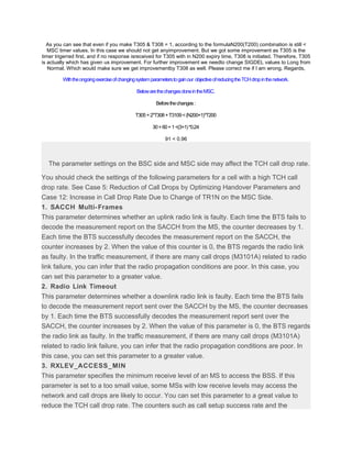
1. As you can see that even if you make T305 & T308 = 1, according to the formulaN200(T200) combination is still <
MSC timer values. In this case we should not get anyimprovement. But we got some improvement as T305 is the
timer trigerred first, and if no response isreceived for T305 with in N200 expiry time, T308 is initiated. Therefore, T305
is actually which has given us improvement. For further improvement we needto change SIGDEL values to Long from
Normal. Which would make sure we get improvementby T308 as well. Please correct me if I am wrong. Regards,
Withtheongoingexerciseofchangingsystemparameterstogainour objectiveofreducingtheTCHdropinthenetwork.
BelowarethechangesdoneintheMSC.
Beforethechanges:
T305+2*T308+T3109<(N200+1)*T200
30+60+1<(3+1)*0.24
91 < 0.96
The parameter settings on the BSC side and MSC side may affect the TCH call drop rate.
You should check the settings of the following parameters for a cell with a high TCH call
drop rate. See Case 5: Reduction of Call Drops by Optimizing Handover Parameters and
Case 12: Increase in Call Drop Rate Due to Change of TR1N on the MSC Side.
1. SACCH Multi-Frames
This parameter determines whether an uplink radio link is faulty. Each time the BTS fails to
decode the measurement report on the SACCH from the MS, the counter decreases by 1.
Each time the BTS successfully decodes the measurement report on the SACCH, the
counter increases by 2. When the value of this counter is 0, the BTS regards the radio link
as faulty. In the traffic measurement, if there are many call drops (M3101A) related to radio
link failure, you can infer that the radio propagation conditions are poor. In this case, you
can set this parameter to a greater value.
2. Radio Link Timeout
This parameter determines whether a downlink radio link is faulty. Each time the BTS fails
to decode the measurement report sent over the SACCH by the MS, the counter decreases
by 1. Each time the BTS successfully decodes the measurement report sent over the
SACCH, the counter increases by 2. When the value of this parameter is 0, the BTS regards
the radio link as faulty. In the traffic measurement, if there are many call drops (M3101A)
related to radio link failure, you can infer that the radio propagation conditions are poor. In
this case, you can set this parameter to a greater value.
3. RXLEV_ACCESS_MIN
This parameter specifies the minimum receive level of an MS to access the BSS. If this
parameter is set to a too small value, some MSs with low receive levels may access the
network and call drops are likely to occur. You can set this parameter to a great value to
reduce the TCH call drop rate. The counters such as call setup success rate and the
2. counters related to traffic volume, however, are accordingly affected.
4. RACH Min.Access Level
This parameter determines whether an MS can access the network over the RACH. If this
parameter is set to a too small value, some MSs with low signal levels may access the
network and call drops are likely to occur. You can set this parameter to a great value to
reduce the TCH call drop rate. The counters such as call setup success rate and paging
success rate, however, are affected.
5. Min DL Power on HO Candidate Cell and Min Access Level Offset
The sum of the values of the two parameters specifies the minimum downlink receive level
of a candidate neighboring cell for a handover. If this parameter is set to a too great value,
some desired cells may be excluded from the candidate cells; if this parameter is set to a
too small value, an unwanted cell may become the candidate cell. Both conditions may lead
to the increase of call
drops.
6. Timer T3103 series
Timer T3101 series consists of T3103A, T3103C, and T8. These timers are started to wait
for a handover complete message. If the lengths of the timers are set to small values,
probably no message is received when timer T3103 series expires. In this case, the BSC
considers that the radio link in the originating cell is faulty. Then, the BSC releases the
channel in the originating cell. Thus, call drops occur. In the traffic measurement, if many
call drops are related to handovers (CM331: Call Drops on Radio Interface in Handover
State), you can set this parameter to a greater value. If this parameter is set to a too great
value, channel resources are wasted and
TCH congestion occurs.
7. Timer T3109
This parameter specifies the period for waiting for a Release Indication message after the
BSC sends a Channel Release message to the BTS. If this parameter is set to a too small
value, the link may be released before the Release Indication message is received. As a
result, a call drop occurs. You can set this parameter to a greater value to reduce the TCH
call drop rate. It is recommended that timer T3109 be set to 1–2 seconds longer than timer
Radio Link Timeout.
8. Timer T3111
This parameter specifies the interval between the time that the main signaling link is
disconnected and the time that a channel is deactivated. The purpose is to reserve a period
of time for repeated link disconnections. If this timer is set to a too small value, a channel
may be deactivated too early. Thus, call drops increase.
3. 9. Timers T305 and T308
Timers T305 and T308 are used on the MSC side. Timer T305 specifies the period during
which the MSC monitors the on-hook procedure. Timer T308 specifies the period during
which the MSC monitors the resource release procedure. You should set the two
parameters when adding BSC data. Note that the modification of the data in the timer table
does not take effect. If timers T305 and T308 are set to invalid or great values, the MSC
clears the call a long time after the MS hangs up. After the T3103 and Radio Link
Timeout timers expire, the number of call drops is increased and thus the TCH call drop rate
is significantly affected.
10. TCH Traffic Busy Threshold
If the current channel seizure ratio exceeds the value of this parameter, the BSC
preferentially assigns a half-rate channel to a dualrate-enabled call. Otherwise, the BSC
assigns a full-rate channel to the dualrate-enabled call. Compared with a full-rate channel, a
half-rate channel has weak antiinterference capabilities. Therefore, if a large number of half-
rate channels are assigned, the TCH call drop rate increases. It is recommended that this
parameter should not be set to a too small value if congestion is unlikely to
occur.
11. Call Reestablishment Forbidden
This parameter specifies whether to allow call reestablishment. In case of burst interference
or radio link failure due to blind areas caused by high buildings, call drops occur. In this
case, MSs can initiate the call reestablishment procedure to restore communication. To
reduce the TCH call drop rate, you can set this parameter to No to allow call
reestablishment. In certain conditions, allowing call reestablishment greatly reduces the
TCH call drop rate. Call reestablishment lasts for a long time, and therefore some
subscribers cannot wait and hang up. This affects user experience.
12. Parameters related to edge handover
When the receive level drops greatly, an edge handover cannot be performed in time in any
of the following conditions: The parameter Edge HO UL RX_LEV Threshold or Edge HO DL
RX_LEV Threshold is set to a small value; the parameter Inter-cell HO Hysteresis is set to a
great value; the parameters Edge HO Watch Time and Edge HO AdjCell Watch Time
are set to great values; the parameters Edge HO Valid Time and Edge HO AdjCell Valid
Time are set to great values. As a result, a call drop occurs. To reduce the TCH call drop
rate, you can appropriately set these parameters so that edge handovers can be performed
in time to avoid call drops.
13. Parameters related to BQ handover
When the signal quality deteriorates, a BQ handover cannot be performed in time in any of
4. the following conditions: The parameters
ULQuaLimitAMRFR, ULQuaLimitAMRHR, UL Qual. Threshold, DLQuaLimitAMRFR,
DLQuaLimitAMRHR, and DL Qual. Threshold are
set to great values; the parameter BQ HO Margin is set to a small value; the parameter
Inter-cell HO Hysteresis is set to a great value. As a result, call drops occur. To reduce the
TCH call drop rate, you should appropriately set these parameters so that BQ handovers
can be performed in time to avoid call drops.
14. Parameters related to interference handover
If the parameters RXQUAL1 to RXQUAL12 are set to great values or if the RXLEVOff
parameter is set to a great value, strong interference may occur. In this case, if interference
handovers are not performed in time, call drops occur. To reduce the TCH call drop rate,
you can appropriately set these parameters so that interference handovers can be
performed in time to avoid call drops. If the parameters RXQUAL1 to RXQUAL12 are set to
small values, the number of handovers due to other causes increases greatly, thus affecting
the handover success rate.
15. Parameters related to concentric cell handover
A call at the edge of the overlaid subcell cannot be handed over to the underlaid subcell in
any of the following conditions: In the case of a normal concentric cell, the parameters
RX_LEV Threshold and RX_LEV Hysteresis are set to great values; in the case of an
enhanced concentric cell, the parameter OtoU HO Received Level Threshold is set to a
great value. As a result, a call drop is likely to occur. If the Call Drop Ratio on TCH on the
TRX in the OverLaid Subcell (RM330a) is high, you can appropriately set these parameters
so that calls at the edge of the overlaid subcell can be handed over to the underlaid subcell
in time. When a call in the underlaid subcell has interference, the call cannot be handed
over to the overlaid subcell if the RX_QUAL for UO HO Allowed parameter is set to Yes and
the RX_QUAL Threshold parameter is set to a great value. Thus, a call drop occurs. If the
Call Drop Ratio on TCH on the TRX in the Underlaid Subcell (RM330) is high, you can set
these parameters properly so that the call can be handed over to the overlaid
subcell at the earliest.
16. Parameters related to power control
If the power control level and quality threshold are set to small values, call drops are likely to
occur because of low signal level or bad voice quality.
17. T200 and N200
If the parameters T200 FACCH/F, T200 FACCH/H, N200 of FACCH/Full rate, and N200 of
FACCH/Half rate are set to small values, data links are disconnected too early. Thus, all
drops are likely to occur. If call drops occur because of T200 expiry, you can increase the
values of T200 and N200 properly.
5. 18. Neighboring cell relations
If the neighboring cells configured in the BA2 table are incomplete, call drops are likely to
occur in the case of no suitable neighboring cell for handover and progressive deterioration
in the voice quality. Neighboring cell relations should be configured completely on the basis
of the drive test data and electronic map (for example, Nastar) to minimize the call drops
due to no available neighboring cells.
19. MAIO
If frequency hopping (FH) is applied in a cell and the MAIO is set inappropriately (for
example, different TRXs serving the same cell have the same MAIO), frequency collision
may occur during FH. Thus, the TCH call drop rate increases.
20. Disconnect Handover Protect Timer
This parameter is a software parameter of the BSC. After receiving a DISCONNECT
message from an MS, the BSC cannot hand over the MS within the period specified by this
parameter. Therefore, the following case can be avoided: After being handed over to the
target cell, the MS cannot be put on hook because it does not receive a release
acknowledgement message. You are advised to set this parameter properly.
21. TR1N
This parameter should be set on the MSC side. It is used to avoid the retransmission of
short messages. When this parameter is set to a too great value, the MSC does not send a
CLEAR CMD message if the MS receives a short message during link disconnection. As a
result, the MS sends the BTS a DISC message to disconnect layer 2 connection. After
receiving the DISC message, the BTS sends a REL_IND message to the BSC. Then, the
BSC sends a CLEAR REQ message to the MSC and the number of call drops is
incremented by one.
22. Software Parameter 13 and MAX TA
When the parameter Software Parameter 13 is enabled and the parameter MAX TA is set to
a too small value, the channel is released when the TA of a call exceeds the MAX TA. In
this case, call drops occur. It is recommended that the parameter Software Parameter 13
should not be enabled.
23. Directly Magnifier Site Flag
If a BTS is installed with repeaters, the handover between repeaters can only be
asynchronous because the distance between repeaters is long. If synchronous handovers
are performed, the handovers may fail and thus many call drops occur. Therefore, when a
BTS is installed with repeaters, the parameter Directly Magnifier Site Flag should be set to
Yes to avoid asynchronous handovers between cells under the same BTS.
6. Cv a
I assume that your coleague changed the MSC side timer T305 and T308, your coleague did a "clever" trick
to let the MSC clear the call early before the BSS side peg the drop call statistics. In long run, your coleague
just plays around these timer parameters and doesn't improve the network quality. I saw similar actions
before.
Here are the explanation what these 2 timers are used for.
T305 timer is started at the MSC/MS when DTAP message DISCONNECT is sent, this will guard the
DISCONNECT procedure run correctly in T305 period.
T308 timer is started at the MSC/MS when DTAP message RELEASE is sent after the DISCONNECT
procedure, this timer guards how long the RELEASE procedure runs.
(GSM 04.08 section 5.4 call clearing)
T305 and T308 at MSC should be set to no less than 11 seconds to guarantee that the layer 2 T200 is timing
out N200 times on the air interface, reducing these timers to less than 11 seconds will pull them below the
related BSS timers[T200*(N200+1) in this case] at the air
interface that are used to ensure a successful transmission of a message (DISCONNECT and RELEASE in this
case) to/from the mobile over the air interface. Normally the higher level MSC timers would be set longer
than the related lower level times in the BSS, using a strategy that lower level timers should expire first.
Setting T305 and T308 to less than 11 seconds here is forced the higher level MSC timers to expire before
the BSS timers[T200*(N200+1) and link_fail(only for MSC issuing DISCONNECT/RELEASE first)] when there
are air interface transmission problems (RF interference) for DISCONNECT and RELEASE signalling, and as a
result the BSS statistics SD/TCH drop doesn't get a chance to peg for T200*(N200+1).
The end user experience is probably not that relevant here as they were trying to clear the call anyway. The
end user would see no difference.
However the network operator could be fooled here though thinking that he has a clean RF interface with a
lower drop call rate, when in fact there could be RF interference issues to be resolved. The low MSC timers
are just masking it.
7. Cv a
I assume that your coleague changed the MSC side timer T305 and T308, your coleague did a "clever" trick
to let the MSC clear the call early before the BSS side peg the drop call statistics. In long run, your coleague
just plays around these timer parameters and doesn't improve the network quality. I saw similar actions
before.
Here are the explanation what these 2 timers are used for.
T305 timer is started at the MSC/MS when DTAP message DISCONNECT is sent, this will guard the
DISCONNECT procedure run correctly in T305 period.
T308 timer is started at the MSC/MS when DTAP message RELEASE is sent after the DISCONNECT
procedure, this timer guards how long the RELEASE procedure runs.
(GSM 04.08 section 5.4 call clearing)
T305 and T308 at MSC should be set to no less than 11 seconds to guarantee that the layer 2 T200 is timing
out N200 times on the air interface, reducing these timers to less than 11 seconds will pull them below the
related BSS timers[T200*(N200+1) in this case] at the air
interface that are used to ensure a successful transmission of a message (DISCONNECT and RELEASE in this
case) to/from the mobile over the air interface. Normally the higher level MSC timers would be set longer
than the related lower level times in the BSS, using a strategy that lower level timers should expire first.
Setting T305 and T308 to less than 11 seconds here is forced the higher level MSC timers to expire before
the BSS timers[T200*(N200+1) and link_fail(only for MSC issuing DISCONNECT/RELEASE first)] when there
are air interface transmission problems (RF interference) for DISCONNECT and RELEASE signalling, and as a
result the BSS statistics SD/TCH drop doesn't get a chance to peg for T200*(N200+1).
The end user experience is probably not that relevant here as they were trying to clear the call anyway. The
end user would see no difference.
However the network operator could be fooled here though thinking that he has a clean RF interface with a
lower drop call rate, when in fact there could be RF interference issues to be resolved. The low MSC timers
are just masking it.