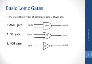
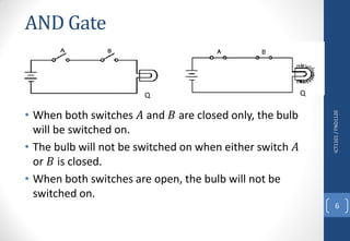
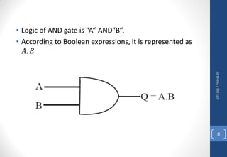
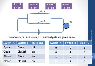
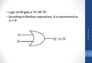
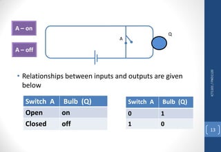
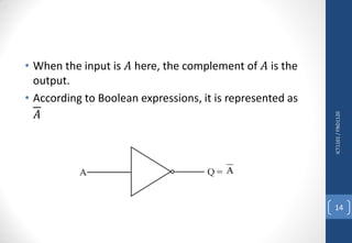
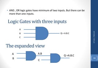
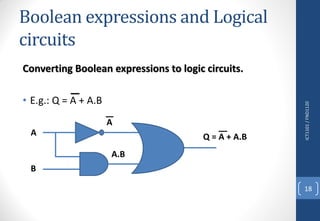
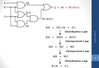
Logic Signals
• A voltage signal with zero (0) corresponding to 0V
and one (1) corresponding to 5V or 3V.
• Switches, OPEN for "0" and CLOSED for "1".
• Modern digital computers store and process all kinds of
information as binary patterns.
• All the pictures, text. sound and video stored in this
computer are held as patterns of binary values.
ICT1101/FND1120
1
ICT1101/FND1120
2
1 0 1 0 1 0 1 0
5v
0v
Logic Gates
• The Logic Gate is the basic building block of electronic circuits.
Central Processing Unit is made up of a collection of a large number
of logic gates.
• Basic logic gates perform logical operations of AND, OR and NOT on
binary numbers.
• Two voltage levels (High and Low), are represented in Boolean
Algebra. (in a standard truth tables it is denoted by binary digits
of “1” and “0”).
ICT1101/FND1120
3
Boolean Algebra Voltage State
1 High (5V/3V)
0 Low (0V)
How to develop the truth table
ICT1101/FND1120
4
• If there are 2 inputs, number of states = 22 = 4
• If there are 3 inputs, number of states = 23 = 8
• If there are 𝒏 inputs, number of states = 2n
Basic Logic Gates
• There are three types of basic logic gates. Those are,
1. AND gate
2. OR gate
3. NOT gate
ICT1101/FND1120
5
AND Gate
• When both switches 𝐴 and 𝐵 are closed only, the bulb
will be switched on.
• The bulb will not be switched on when either switch 𝐴
or 𝐵 is closed.
• When both switches are open, the bulb will not be
switched on.
ICT1101/FND1120
6
QQ
ICT1101/FND1120
7
A
Q
B
• Relationships between inputs and outputs are given
below
Switch A Switch B Bulb Q
Open Open off
Open Closed off
Closed Open off
Closed Closed on
Switch A Switch B Bulb Q
0 0 0
0 1 0
1 0 0
1 1 1
ICT1101/FND1120
8
• Logic of AND gate is “A” AND“B”.
• According to Boolean expressions, it is represented as
𝐴. 𝐵
OR Gate
ICT1101/FND1120
9
• Relationships between inputs and outputs are given below
ICT1101/FND1120
10
A
QB
Switch A Switch B Bulb (Q)
Open Open off
Open Closed on
Closed Open on
Closed Closed on
Switch A Switch B Bulb (Q)
0 0 0
0 1 1
1 0 1
1 1 1
ICT1101/FND1120
11
• Logic of OR gate is “A” OR “B”.
• According to Boolean expressions, it is represented as
𝐴 + 𝐵
NOT Gate
• The task of the NOT gate is to provide the complement
as the output.
• Thus, complement of “0” is “1” and the complement of
“1” is “0”.
ICT1101/FND1120
12
ICT1101/FND1120
13
• Relationships between inputs and outputs are given
below
A
Q
Switch A Bulb (Q)
Open on
Closed off
Switch A Bulb (Q)
0 1
1 0
• When the input is 𝐴 here, the complement of 𝐴 is the
output.
• According to Boolean expressions, it is represented as
𝐴
ICT1101/FND1120
14
Other Logic Gates
• NAND Gate
• NOR Gate
• XOR Gate
• XNOR Gate
ICT1101/FND1120
15
Logic Gates with three inputs
• AND , OR logic gates have minimum of two inputs. But there can be
more than one inputs.
ICT1101/FND1120
16
A
B
C
Q = A.B.C
The expanded view
A
B
C
A.B
Q =A.B.C
Exercise
1. How many states there can be for an OR gate
with three inputs?
2. Draw the expanded view of the above gate.
3. Develop a truth table for the OR gate mentioned
above
ICT1101/FND1120
17
Boolean expressions and Logical
circuits
Converting Boolean expressions to logic circuits.
• E.g.: Q = A + A.B
ICT1101/FND1120
18
A
B
A
A.B
Q = A + A.B
Converting Logic circuits to Boolean expressions.
E.g.:
ICT1101/FND1120
19
A
B
C
𝑄 = 𝐴 + 𝐵 . 𝐶
ICT1101/FND1120
20
Thank You
ICT1101/FND1120
21

logic signals

  • 1.
    Logic Signals • Avoltage signal with zero (0) corresponding to 0V and one (1) corresponding to 5V or 3V. • Switches, OPEN for "0" and CLOSED for "1". • Modern digital computers store and process all kinds of information as binary patterns. • All the pictures, text. sound and video stored in this computer are held as patterns of binary values. ICT1101/FND1120 1
  • 2.
    ICT1101/FND1120 2 1 0 10 1 0 1 0 5v 0v
  • 3.
    Logic Gates • TheLogic Gate is the basic building block of electronic circuits. Central Processing Unit is made up of a collection of a large number of logic gates. • Basic logic gates perform logical operations of AND, OR and NOT on binary numbers. • Two voltage levels (High and Low), are represented in Boolean Algebra. (in a standard truth tables it is denoted by binary digits of “1” and “0”). ICT1101/FND1120 3 Boolean Algebra Voltage State 1 High (5V/3V) 0 Low (0V)
  • 4.
    How to developthe truth table ICT1101/FND1120 4 • If there are 2 inputs, number of states = 22 = 4 • If there are 3 inputs, number of states = 23 = 8 • If there are 𝒏 inputs, number of states = 2n
  • 5.
    Basic Logic Gates •There are three types of basic logic gates. Those are, 1. AND gate 2. OR gate 3. NOT gate ICT1101/FND1120 5
  • 6.
    AND Gate • Whenboth switches 𝐴 and 𝐵 are closed only, the bulb will be switched on. • The bulb will not be switched on when either switch 𝐴 or 𝐵 is closed. • When both switches are open, the bulb will not be switched on. ICT1101/FND1120 6 QQ
  • 7.
    ICT1101/FND1120 7 A Q B • Relationships betweeninputs and outputs are given below Switch A Switch B Bulb Q Open Open off Open Closed off Closed Open off Closed Closed on Switch A Switch B Bulb Q 0 0 0 0 1 0 1 0 0 1 1 1
  • 8.
    ICT1101/FND1120 8 • Logic ofAND gate is “A” AND“B”. • According to Boolean expressions, it is represented as 𝐴. 𝐵
  • 9.
  • 10.
    • Relationships betweeninputs and outputs are given below ICT1101/FND1120 10 A QB Switch A Switch B Bulb (Q) Open Open off Open Closed on Closed Open on Closed Closed on Switch A Switch B Bulb (Q) 0 0 0 0 1 1 1 0 1 1 1 1
  • 11.
    ICT1101/FND1120 11 • Logic ofOR gate is “A” OR “B”. • According to Boolean expressions, it is represented as 𝐴 + 𝐵
  • 12.
    NOT Gate • Thetask of the NOT gate is to provide the complement as the output. • Thus, complement of “0” is “1” and the complement of “1” is “0”. ICT1101/FND1120 12
  • 13.
    ICT1101/FND1120 13 • Relationships betweeninputs and outputs are given below A Q Switch A Bulb (Q) Open on Closed off Switch A Bulb (Q) 0 1 1 0
  • 14.
    • When theinput is 𝐴 here, the complement of 𝐴 is the output. • According to Boolean expressions, it is represented as 𝐴 ICT1101/FND1120 14
  • 15.
    Other Logic Gates •NAND Gate • NOR Gate • XOR Gate • XNOR Gate ICT1101/FND1120 15
  • 16.
    Logic Gates withthree inputs • AND , OR logic gates have minimum of two inputs. But there can be more than one inputs. ICT1101/FND1120 16 A B C Q = A.B.C The expanded view A B C A.B Q =A.B.C
  • 17.
    Exercise 1. How manystates there can be for an OR gate with three inputs? 2. Draw the expanded view of the above gate. 3. Develop a truth table for the OR gate mentioned above ICT1101/FND1120 17
  • 18.
    Boolean expressions andLogical circuits Converting Boolean expressions to logic circuits. • E.g.: Q = A + A.B ICT1101/FND1120 18 A B A A.B Q = A + A.B
  • 19.
    Converting Logic circuitsto Boolean expressions. E.g.: ICT1101/FND1120 19 A B C 𝑄 = 𝐴 + 𝐵 . 𝐶
  • 20.
  • 21.