Download to read offline
![Load Balancer Configuration
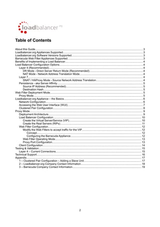
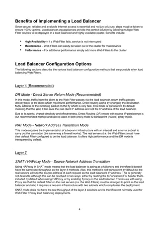
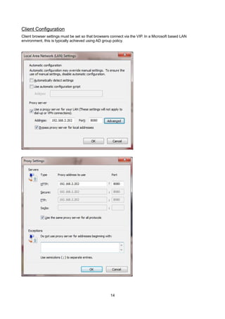
Create the Virtual Server/Service (VIP)
NOTE: Prior to v7.5 a VIP is known as a 'Virtual Server', from v7.5 onwards it's known as a 'Virtual
Service'. For simplicity the configuration steps below refer to 'Virtual Service' for both.
•
v7.5 & later – using the WUI go to Cluster Configuration > Layer 4 – Virtual Services
•
v7.4.3 – using the WUI go to Edit Configuration > Layer 4 – Virtual Servers
•
Click [Add a New Virtual Service]
•
Enter the following details:
•
Enter an appropriate label (name) for the VIP, e.g. Proxy
•
Set the Virtual Service IP address field to the required IP address, e.g. 192.168.2.202
•
Set the Virtual Service Ports field to the required port (the same as the Web Filters) , e.g. 8080
•
Ensure that Forwarding Method is set to Direct Return
•
Set Persistent to yes
•
Ensure that Protocol is set to TCP
•
Click Update
10](https://image.slidesharecdn.com/load-balancer-deployment-guide-fr-barracuda-web-filter-140203104516-phpapp02/85/Handbuch-zum-Load-Balancing-des-Barracuda-Webfilters-10-320.jpg)
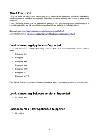
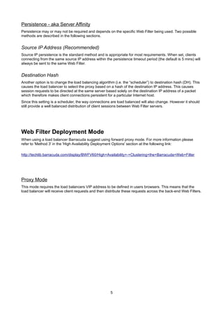
![Create the Real Servers (RIPs)
•
v7.5 & later – using the WUI go to Cluster Configuration > Layer 4 – Real Servers
•
v7.4.3 – using the WUI go to Edit Configuration > Layer 4 – Real Servers
•
Click [Add a new Real Server] next to the newly created VIP
•
Enter the following details:
•
Enter an appropriate label (name) for the first Proxy Server, e.g. Proxy1
•
Change the Real Server IP Address field to the required IP address, e.g. 192.168.2.210
•
Click Update
•
Repeat the above steps to add your other Web Filters
11](https://image.slidesharecdn.com/load-balancer-deployment-guide-fr-barracuda-web-filter-140203104516-phpapp02/85/Handbuch-zum-Load-Balancing-des-Barracuda-Webfilters-11-320.jpg)


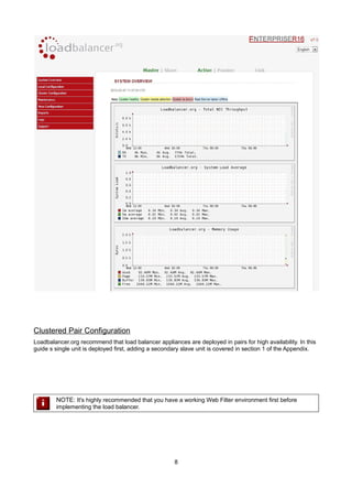
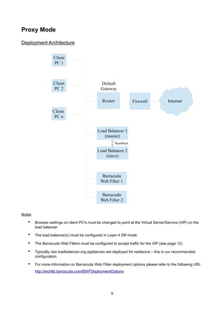
This deployment guide provides instructions for configuring Loadbalancer.org appliances with Barracuda Web Filter products, highlighting supported models and software versions. It covers load balancer configuration options, recommended deployment architectures, and maintenance procedures for high availability. The guide also includes detailed steps for setting up virtual services, real servers, and web filter configurations essential for effective load balancing.