Download to read offline
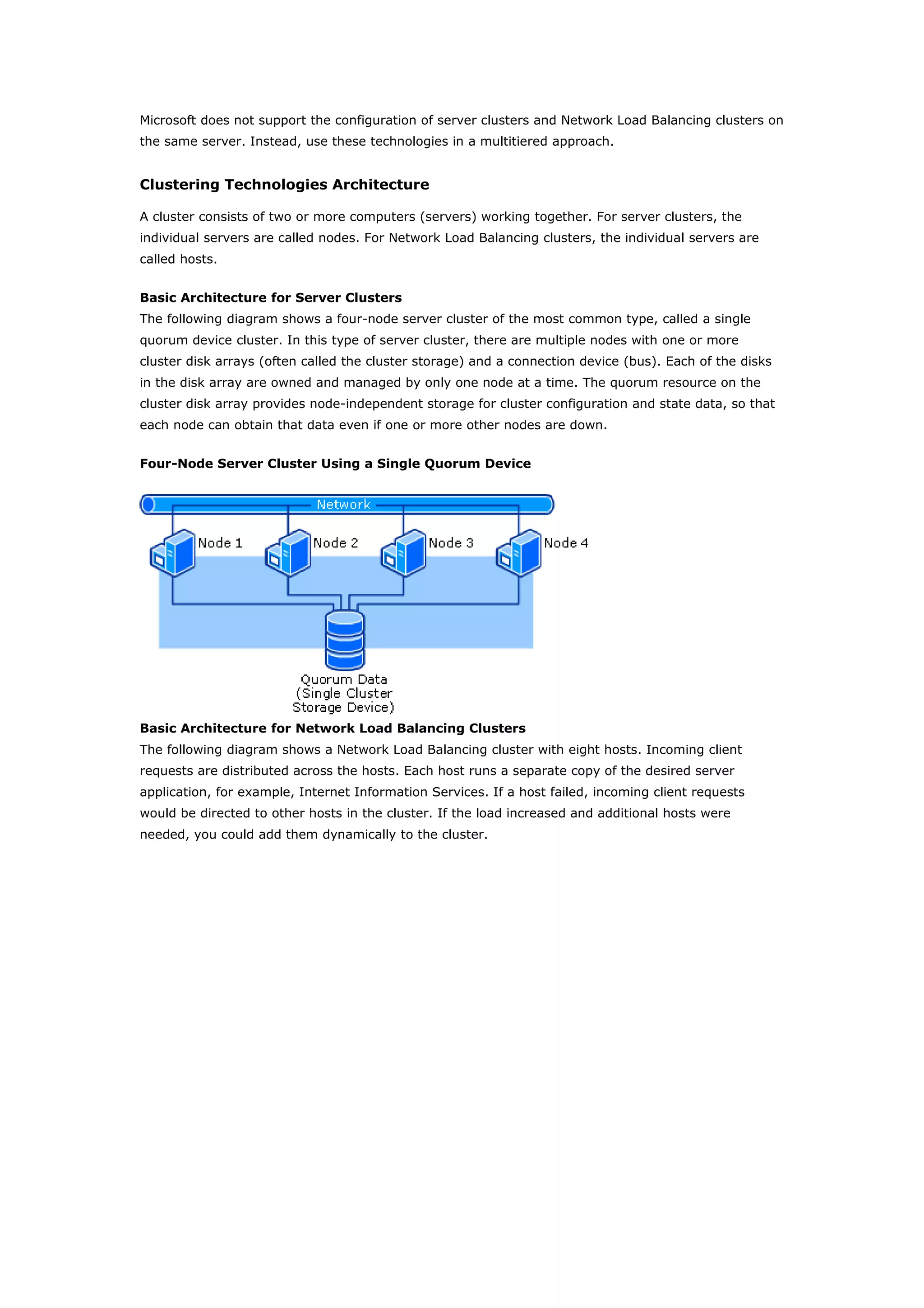
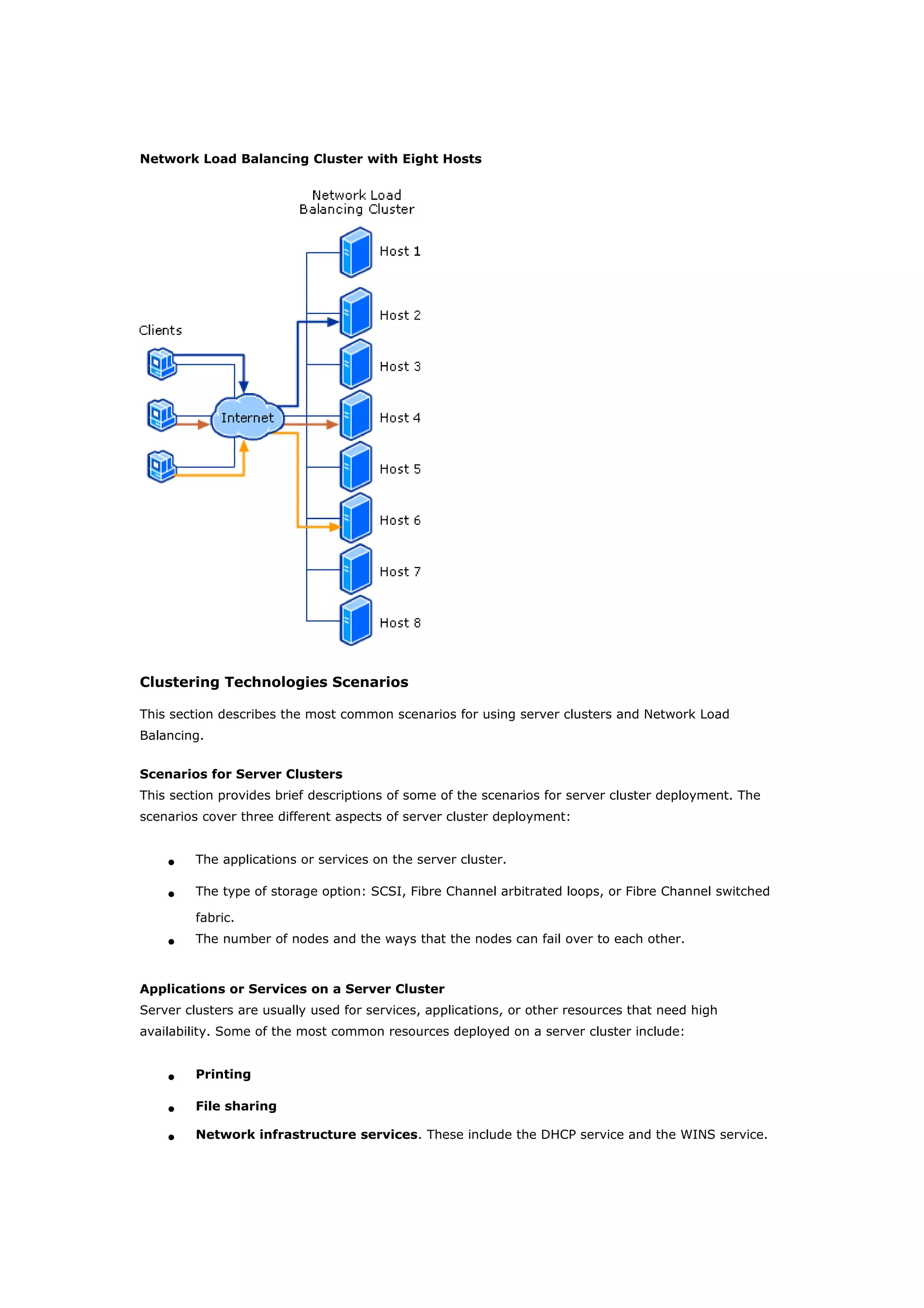
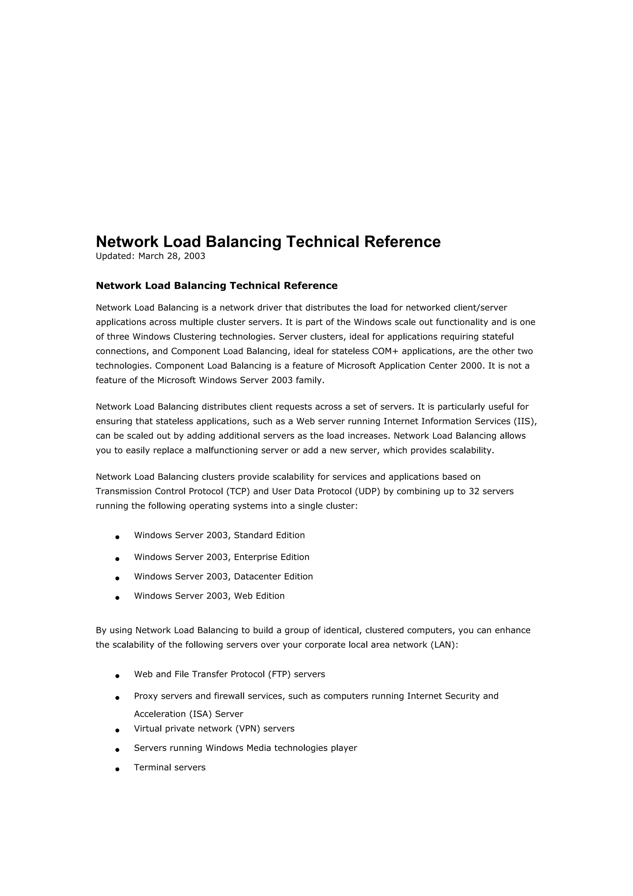


Clustering technologies in Windows Server 2003 help achieve high availability and scalability for critical applications. Server clusters provide high availability by redistributing workloads from failed servers, while Network Load Balancing provides scalability and availability for web services by load balancing requests across multiple servers. The choice depends on whether applications have long-running in-memory state, with server clusters intended for stateful applications like databases and NLB for stateless applications like web servers.