


![b) Direct sensor systems
• The sensor for the radiation image is
usually a Charged Coupled Device [CCD].
It consists of silicon crystals arranged in a
lattice and converts light energy into an
electrical signal.
• This technology is widely used in video
cameras. The sensor cannot store
information and must be connected via fiber
optic wires to the monitor, which can make
the sensor bulky and awkward to use.
www.indiandentalacademy.com](https://image.slidesharecdn.com/limitationsofcephalometricsofceph-160512053339/75/Limitations-of-cephalometrics-of-ceph-159-2048.jpg)


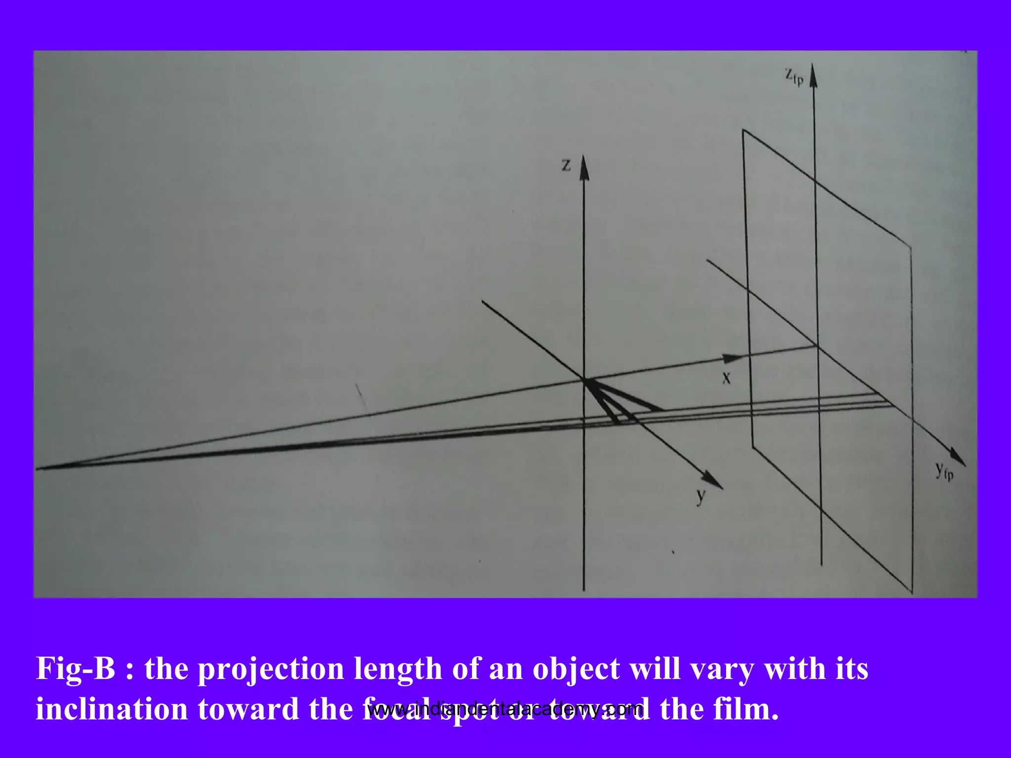
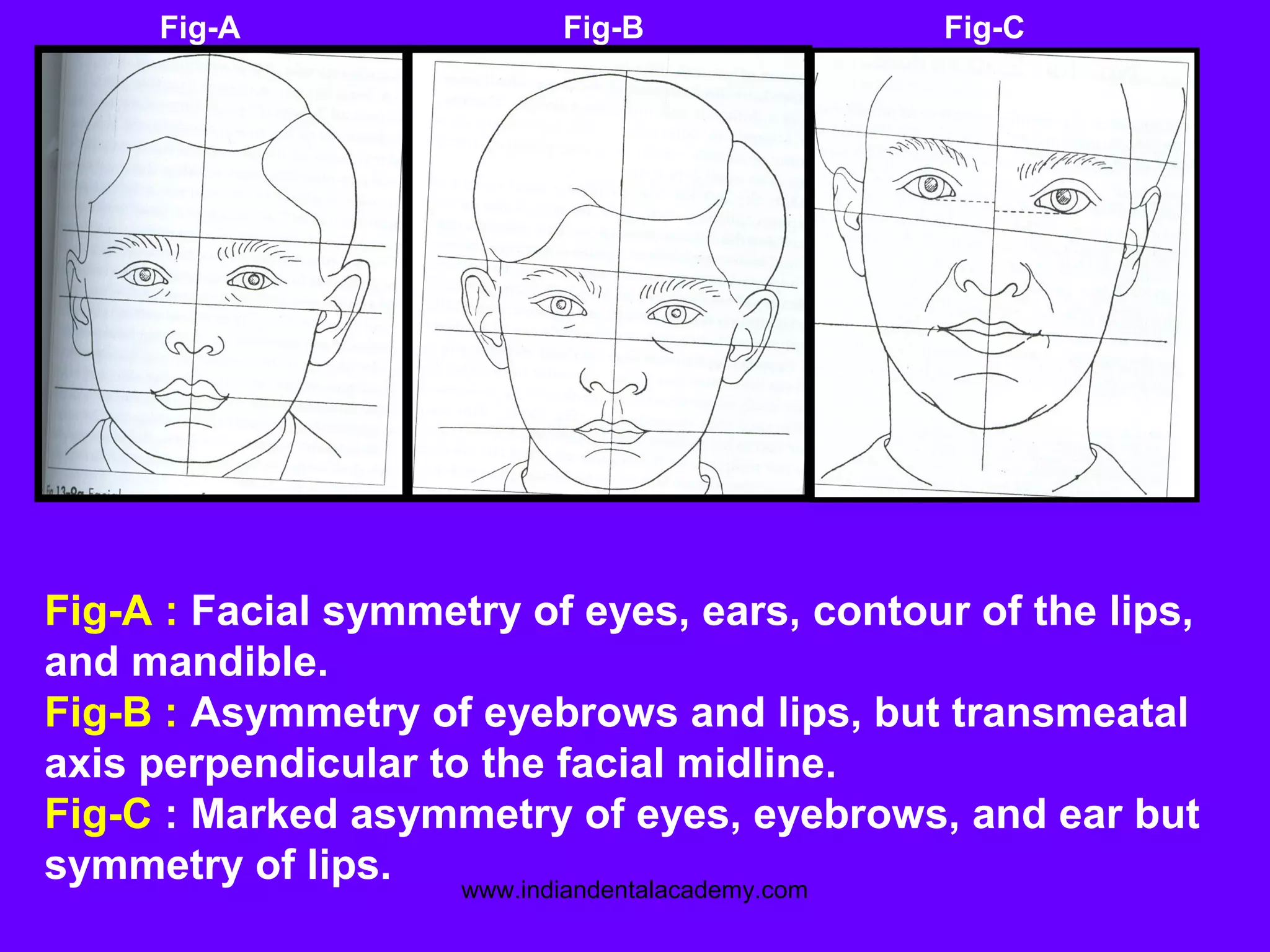
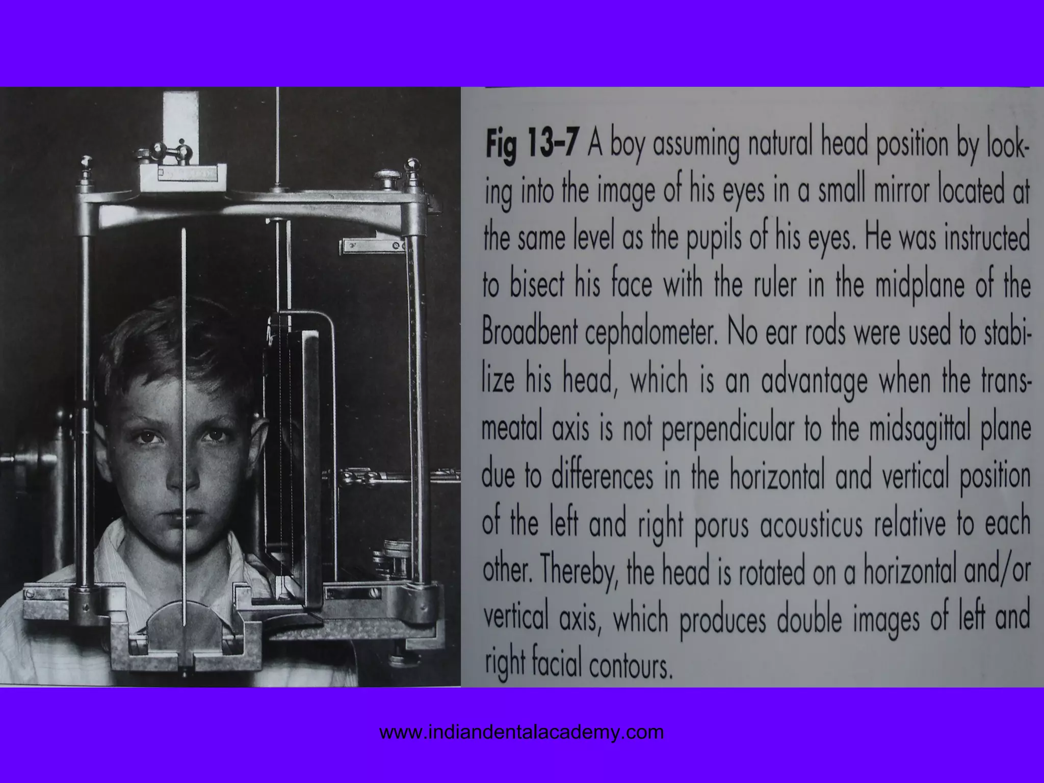
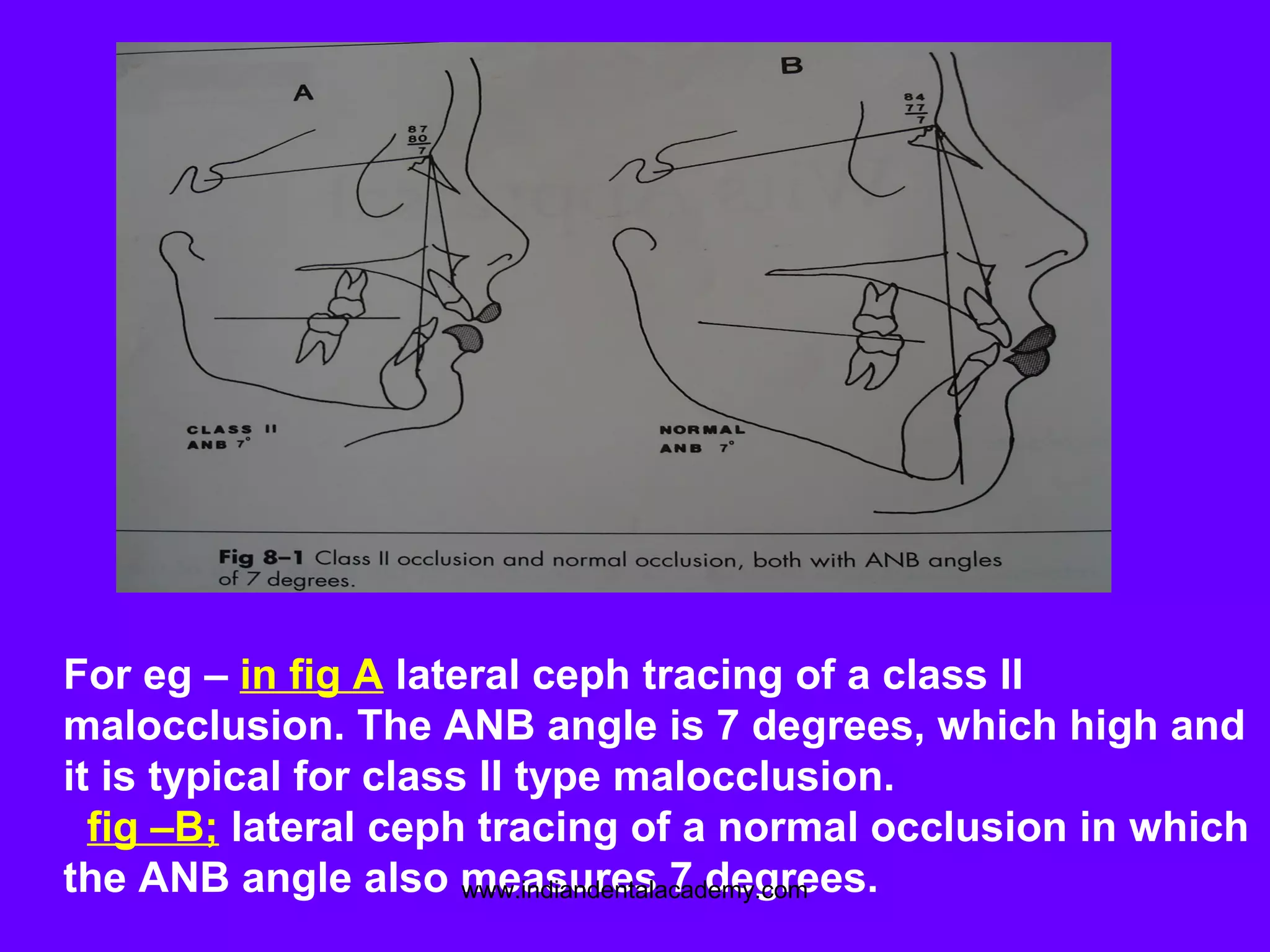
This document discusses the limitations of cephalometrics and includes the following key points: 1. Cephalometrics provides a 2-dimensional representation of a 3-dimensional object, which leads to structural displacement errors. 2. Perfect symmetry is rarely observed due to anatomical variations and image displacement, limiting the ability to accurately assess craniofacial anomalies. 3. Significant errors are associated with locating anatomical landmarks due to a lack of well-defined features in radiographs. Landmark identification errors are a major source of cephalometric error. 4. While cephalometrics is a widely used tool, its use in determining treatment plans based on 2D analyses has been questioned due to inherent technical


