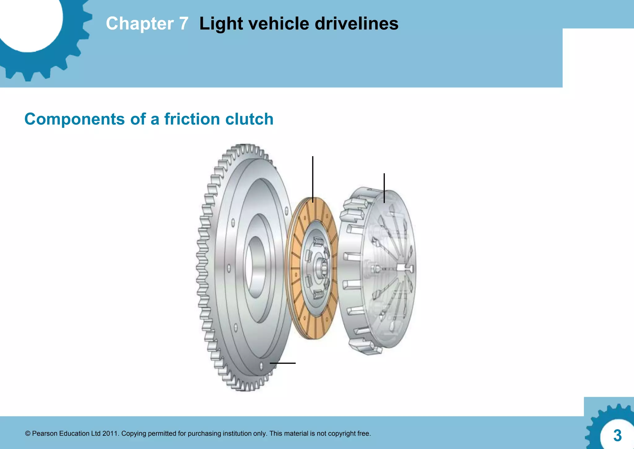
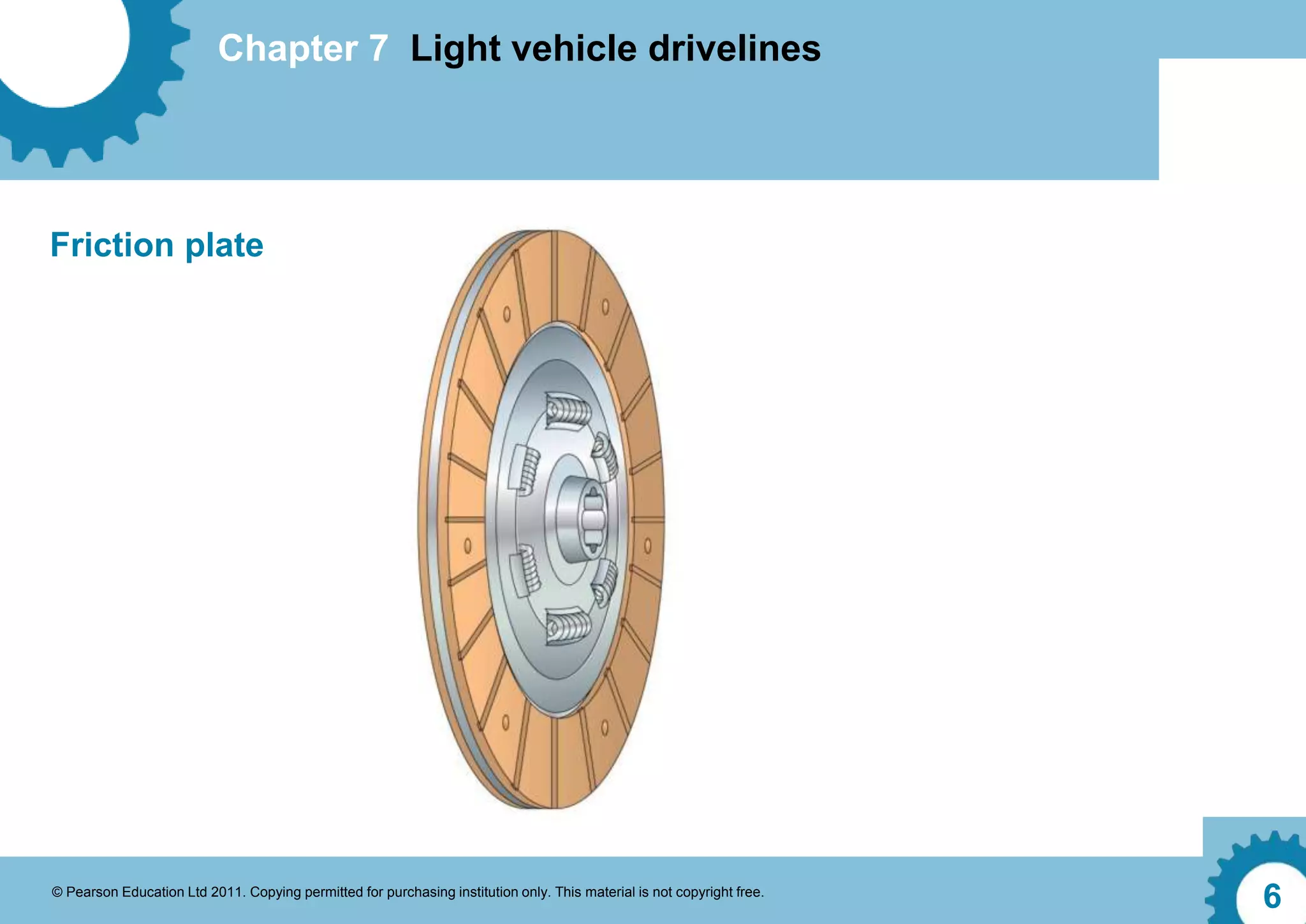
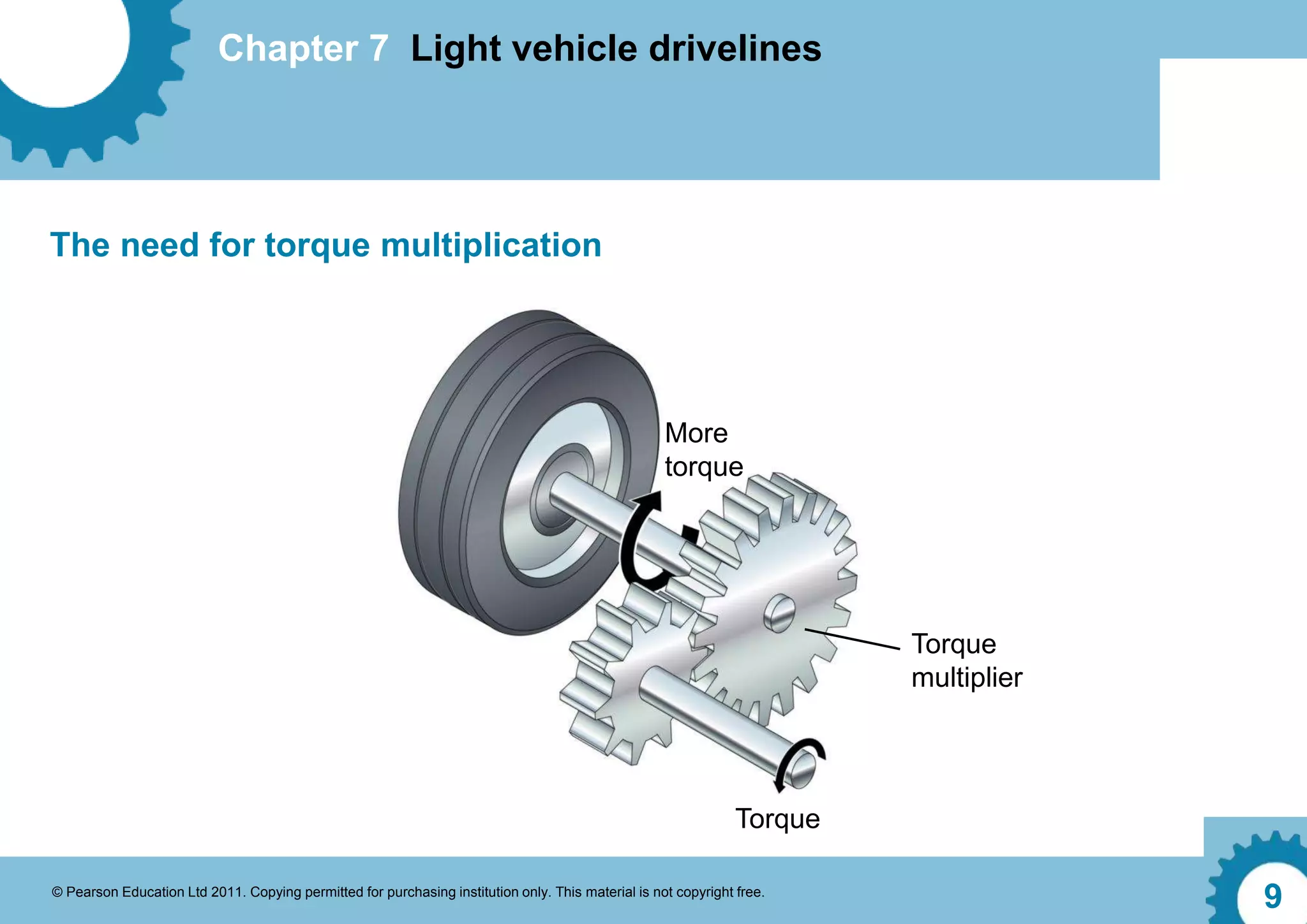
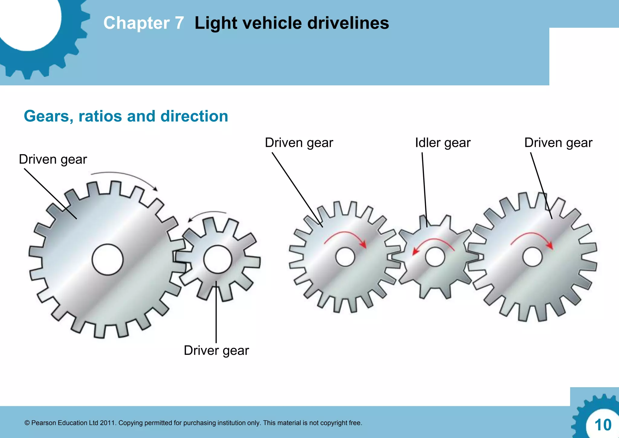
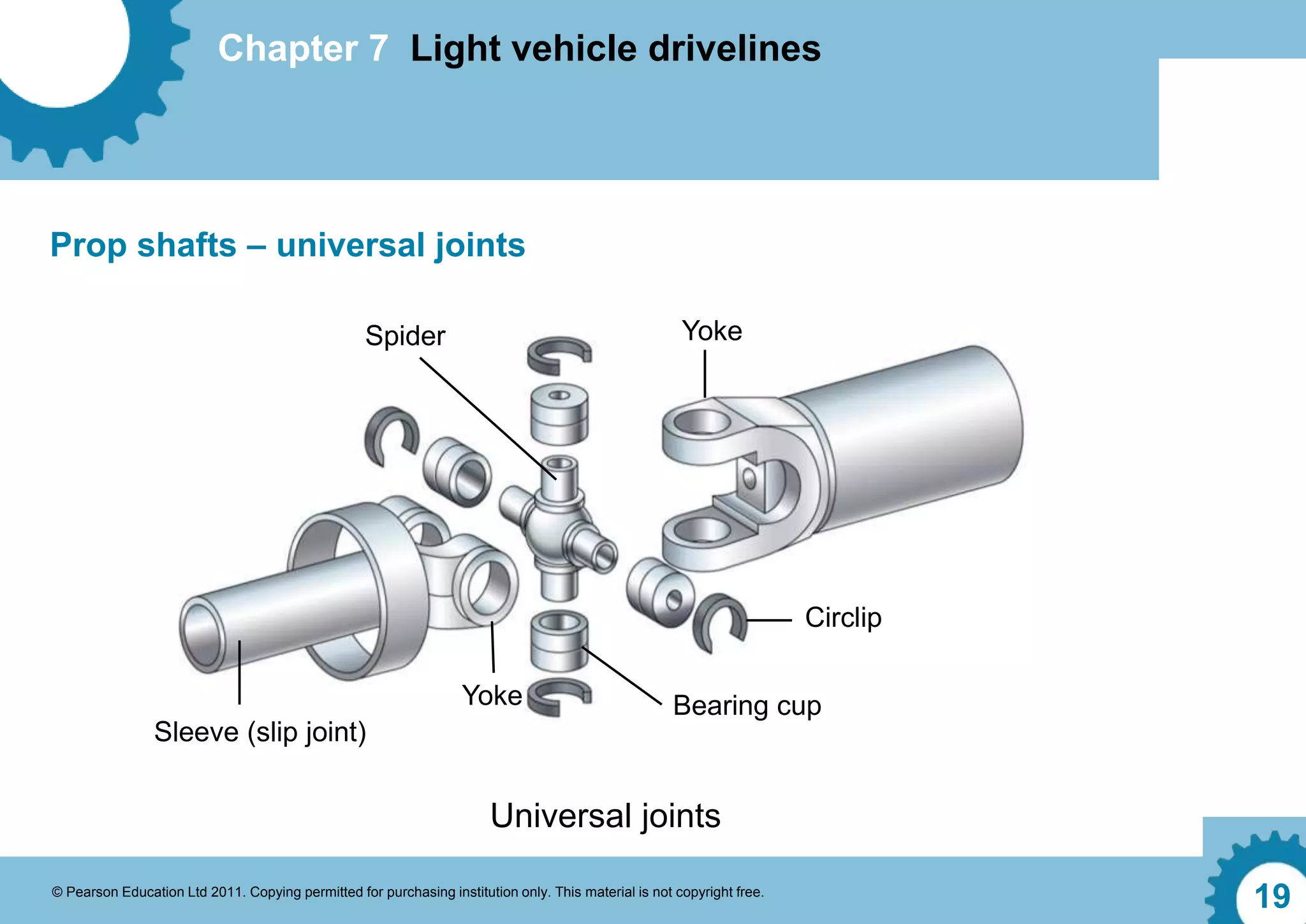
Chapter 7 Light vehicle drivelines
© Pearson Education Ltd 2011. Copying permitted for purchasing institution only. This material is not copyright free.
1
Chapter 7 Light vehicle drivelines
© Pearson Education Ltd 2011. Copying permitted for purchasing institution only. This material is not copyright free.
2
Transmission layout
Drive
wheels Differential
Prop shaft
Transmission
Torque convertor or clutch
Universal joints
Engine
Chapter 7 Light vehicle drivelines
© Pearson Education Ltd 2011. Copying permitted for purchasing institution only. This material is not copyright free.
3
Components of a friction clutch
Chapter 7 Light vehicle drivelines
© Pearson Education Ltd 2011. Copying permitted for purchasing institution only. This material is not copyright free.
4
Clutch operating mechanism – cable operation
Clutch release cable
Clutch cover
Release fork
Clutch pedal
Chapter 7 Light vehicle drivelines
© Pearson Education Ltd 2011. Copying permitted for purchasing institution only. This material is not copyright free.
5
Master cylinder
Clutch cover
Flexible hose
Release fork
Clutch pedal
Release cylinder
Clutch operating mechanism – hydraulic system
Chapter 7 Light vehicle drivelines
© Pearson Education Ltd 2011. Copying permitted for purchasing institution only. This material is not copyright free.
6
Friction plate
Chapter 7 Light vehicle drivelines
© Pearson Education Ltd 2011. Copying permitted for purchasing institution only. This material is not copyright free.
7
Torque converter
Outer housing
Turbine
Stator
Impeller
Chapter 7 Light vehicle drivelines
© Pearson Education Ltd 2011. Copying permitted for purchasing institution only. This material is not copyright free.
8
The need for a gearbox
Torque conversion mechanism
Increased torque
Chapter 7 Light vehicle drivelines
© Pearson Education Ltd 2011. Copying permitted for purchasing institution only. This material is not copyright free.
9
The need for torque multiplication
More
torque
Torque
multiplier
Torque
Chapter 7 Light vehicle drivelines
© Pearson Education Ltd 2011. Copying permitted for purchasing institution only. This material is not copyright free.
10
Gears, ratios and direction
Driver gear
Driven gear
Driven gear Idler gear Driven gear
Chapter 7 Light vehicle drivelines
© Pearson Education Ltd 2011. Copying permitted for purchasing institution only. This material is not copyright free.
11
Gear types
Spur gears Helical gears
Chapter 7 Light vehicle drivelines
© Pearson Education Ltd 2011. Copying permitted for purchasing institution only. This material is not copyright free.
12
Detent mechanism
Spring loaded ball
Selector rod
Neutral position Gear engaged
Chapter 7 Light vehicle drivelines
© Pearson Education Ltd 2011. Copying permitted for purchasing institution only. This material is not copyright free.
13
Selector forks
Selector rod
Detent
Gear lever
Selector hub
Gear selection and interlock
Interlock mechanism
Gear selection mechanism
Neutral position Locked Free
Chapter 7 Light vehicle drivelines
© Pearson Education Ltd 2011. Copying permitted for purchasing institution only. This material is not copyright free.
14
Gear
Synchroniser
Selector hub
Detent
Friction
surfaces
Dog teeth
Selector hub
Chapter 7 Light vehicle drivelines
© Pearson Education Ltd 2011. Copying permitted for purchasing institution only. This material is not copyright free.
15
Drive layouts – front-wheel drive
Engine Clutch Transaxle
Differential
Drive shaft
Chapter 7 Light vehicle drivelines
© Pearson Education Ltd 2011. Copying permitted for purchasing institution only. This material is not copyright free.
16
Drive layouts – rear-wheel drive
Engine
Clutch Propeller shaft
Rear axle shaft
Differential
Transmission
Chapter 7 Light vehicle drivelines
© Pearson Education Ltd 2011. Copying permitted for purchasing institution only. This material is not copyright free.
17
Drive layouts – four-wheel drive
Engine
Driveshaft
Propshaft
Driveshaft
Transaxle
Centre differential
Front differential
Rear differential
Clutch
Chapter 7 Light vehicle drivelines
© Pearson Education Ltd 2011. Copying permitted for purchasing institution only. This material is not copyright free.
18
Prop shafts – movement
Transmission Propeller shaft
Rear axle
Difference
between
arcs
Rear axle
swing arc
Propeller shaft
swing arc
Chapter 7 Light vehicle drivelines
© Pearson Education Ltd 2011. Copying permitted for purchasing institution only. This material is not copyright free.
19
Prop shafts – universal joints
Universal joints
Spider Yoke
Circlip
Bearing cup
Yoke
Sleeve (slip joint)
Chapter 7 Light vehicle drivelines
© Pearson Education Ltd 2011. Copying permitted for purchasing institution only. This material is not copyright free.
20
Constant Velocity (CV) joints
Steel ball
Drive shaft
Ball cage
Outer race
Inner
race
Drive axis Driven axis

Light vehicle drive line.ppt

  • 1.
    Chapter 7 Lightvehicle drivelines © Pearson Education Ltd 2011. Copying permitted for purchasing institution only. This material is not copyright free. 1 Chapter 7 Light vehicle drivelines
  • 2.
    Chapter 7 Lightvehicle drivelines © Pearson Education Ltd 2011. Copying permitted for purchasing institution only. This material is not copyright free. 2 Transmission layout Drive wheels Differential Prop shaft Transmission Torque convertor or clutch Universal joints Engine
  • 3.
    Chapter 7 Lightvehicle drivelines © Pearson Education Ltd 2011. Copying permitted for purchasing institution only. This material is not copyright free. 3 Components of a friction clutch
  • 4.
    Chapter 7 Lightvehicle drivelines © Pearson Education Ltd 2011. Copying permitted for purchasing institution only. This material is not copyright free. 4 Clutch operating mechanism – cable operation Clutch release cable Clutch cover Release fork Clutch pedal
  • 5.
    Chapter 7 Lightvehicle drivelines © Pearson Education Ltd 2011. Copying permitted for purchasing institution only. This material is not copyright free. 5 Master cylinder Clutch cover Flexible hose Release fork Clutch pedal Release cylinder Clutch operating mechanism – hydraulic system
  • 6.
    Chapter 7 Lightvehicle drivelines © Pearson Education Ltd 2011. Copying permitted for purchasing institution only. This material is not copyright free. 6 Friction plate
  • 7.
    Chapter 7 Lightvehicle drivelines © Pearson Education Ltd 2011. Copying permitted for purchasing institution only. This material is not copyright free. 7 Torque converter Outer housing Turbine Stator Impeller
  • 8.
    Chapter 7 Lightvehicle drivelines © Pearson Education Ltd 2011. Copying permitted for purchasing institution only. This material is not copyright free. 8 The need for a gearbox Torque conversion mechanism Increased torque
  • 9.
    Chapter 7 Lightvehicle drivelines © Pearson Education Ltd 2011. Copying permitted for purchasing institution only. This material is not copyright free. 9 The need for torque multiplication More torque Torque multiplier Torque
  • 10.
    Chapter 7 Lightvehicle drivelines © Pearson Education Ltd 2011. Copying permitted for purchasing institution only. This material is not copyright free. 10 Gears, ratios and direction Driver gear Driven gear Driven gear Idler gear Driven gear
  • 11.
    Chapter 7 Lightvehicle drivelines © Pearson Education Ltd 2011. Copying permitted for purchasing institution only. This material is not copyright free. 11 Gear types Spur gears Helical gears
  • 12.
    Chapter 7 Lightvehicle drivelines © Pearson Education Ltd 2011. Copying permitted for purchasing institution only. This material is not copyright free. 12 Detent mechanism Spring loaded ball Selector rod Neutral position Gear engaged
  • 13.
    Chapter 7 Lightvehicle drivelines © Pearson Education Ltd 2011. Copying permitted for purchasing institution only. This material is not copyright free. 13 Selector forks Selector rod Detent Gear lever Selector hub Gear selection and interlock Interlock mechanism Gear selection mechanism Neutral position Locked Free
  • 14.
    Chapter 7 Lightvehicle drivelines © Pearson Education Ltd 2011. Copying permitted for purchasing institution only. This material is not copyright free. 14 Gear Synchroniser Selector hub Detent Friction surfaces Dog teeth Selector hub
  • 15.
    Chapter 7 Lightvehicle drivelines © Pearson Education Ltd 2011. Copying permitted for purchasing institution only. This material is not copyright free. 15 Drive layouts – front-wheel drive Engine Clutch Transaxle Differential Drive shaft
  • 16.
    Chapter 7 Lightvehicle drivelines © Pearson Education Ltd 2011. Copying permitted for purchasing institution only. This material is not copyright free. 16 Drive layouts – rear-wheel drive Engine Clutch Propeller shaft Rear axle shaft Differential Transmission
  • 17.
    Chapter 7 Lightvehicle drivelines © Pearson Education Ltd 2011. Copying permitted for purchasing institution only. This material is not copyright free. 17 Drive layouts – four-wheel drive Engine Driveshaft Propshaft Driveshaft Transaxle Centre differential Front differential Rear differential Clutch
  • 18.
    Chapter 7 Lightvehicle drivelines © Pearson Education Ltd 2011. Copying permitted for purchasing institution only. This material is not copyright free. 18 Prop shafts – movement Transmission Propeller shaft Rear axle Difference between arcs Rear axle swing arc Propeller shaft swing arc
  • 19.
    Chapter 7 Lightvehicle drivelines © Pearson Education Ltd 2011. Copying permitted for purchasing institution only. This material is not copyright free. 19 Prop shafts – universal joints Universal joints Spider Yoke Circlip Bearing cup Yoke Sleeve (slip joint)
  • 20.
    Chapter 7 Lightvehicle drivelines © Pearson Education Ltd 2011. Copying permitted for purchasing institution only. This material is not copyright free. 20 Constant Velocity (CV) joints Steel ball Drive shaft Ball cage Outer race Inner race Drive axis Driven axis

Editor's Notes

  • #2 Tutor notes Aim: To show the function and operation of light vehicle driveline and transmission system units and components. Objective: At the end of this presentation, learners will be able to describe the purpose and operation of light vehicle driveline and transmission units and components.
  • #3 Tutor notes Begin with an overview of a standard transmission layout, showing how each component is linked to the other and transmits drive from the engine to the road wheels.
  • #4 Tutor notes Show the components of a friction clutch. Ask learners to name each component of the friction clutch.
  • #5 Tutor notes Explain the operating mechanisms of friction clutch systems. Describe the advantages and disadvantages of cable operated systems. If appropriate take learners into the workshop and show the operating mechanism in action.
  • #6 Tutor notes Explain the operating mechanisms of friction clutch systems. Describe the advantages and disadvantages of hydraulically operated systems. If appropriate take learners into the workshop and show the operating mechanism in action.
  • #7 Tutor notes Describe the construction of the clutch friction/drive plate. Show the friction material, cushion springs, torsional springs and centre hub. If possible hand a friction plate around the class so that the different sections can be seen.
  • #8 Tutor notes Ask learners the meaning of the word ‘hydraulics’. Answer – the science of movements of liquids. As liquids are virtually incompressible they can be used to operate mechanisms. Explain the function of the components found inside a torque converter. Describe how fluid is taken into the impeller, and thrown outwards into the blades of the turbine by centrifugal force. Upon leaving the turbine, fluid strikes the blades of the stator then turns the impeller at speed multiplying torque.
  • #9 Tutor notes Ask learners why a car needs a gearbox. Answer – to multiply the torque or turning effort produced by the engine, so that it is usable under many different driving conditions.
  • #10 Tutor notes Show how torque and leverage can be multiplied by using gears.
  • #11 Tutor notes Explain the principle of gear ratios – when a small drive gear operates a large driven gear, speed is reduced and torque is multiplied. When a large drive gear operates a small driven gear, speed is increased and torque is reduced. Ask learners to calculate gear ratios from simple given values. Describe the function and operation of an idler gear. Explain that this gear has no effect on overall gear ratio, but merely serves to change the direction of rotation and this is how reverse gear is achieved.
  • #12 Tutor notes Describe the differences between spur and helical gears and the advantages and disadvantages of each. Spur gears act directly and create low amounts of drag, which helps improve overall performance, but can make them noisy in operation. A spur-cut gear can be slid in and out of mesh with another spur-cut gear making them useful as a reverse gear idler. A helical-cut gear has teeth on an angle as shown in the illustration. This means the teeth are not just cut on a diagonal; If they were extended around a cylinder they would actually be shaped like that of a coil spring. Helical-cut gear teeth provide a large surface area making them very strong, less prone to wear and quiet in operation. Unfortunately due to the design and shape of a helical-cut gear they cannot be slid in and out of mesh. This means they have to be used in a gearbox known as a ‘constant-mesh’.
  • #13 Tutor notes Explain that when a gearbox is in operation, thrust from the gear teeth is trying to disengage them. Describe how a detent mechanism operates and helps to keep a selected gear in position. Use a ratchet and socket attachment to show how a detent works (it is similar to how a socket is kept on the end of a ratchet).
  • #14 Tutor notes Gears within a gearbox are turning at different speeds; ask learners what would happen if two different gears were selected at the same time. Answer – the gearbox would lock up and be unable to turn. Describe the process of using an interlock mechanism to prevent two gears being selected at the same time.
  • #15 Tutor notes Describe the operation of a selector hub. Describe the operation of the synchroniser and why a baulk ring mechanism needs to be added to improve gear selection. State how the grooves on the inside of the baulk ring are designed to cut through the surface tension of the lubrication oil to provide grip in the form of a friction clutch. If possible, hand a dismantled synchromesh mechanism around the class, so learners are able to see the different parts.
  • #16 Tutor notes Describe front-wheel drive layout. Ask learners to sketch the drive layout and investigate vehicle manufacturers and types of vehicle which use this drive system.
  • #17 Tutor notes Describe rear-wheel drive layout. Ask learners to sketch this drive layout and investigate vehicle manufacturers and types of vehicle which use this drive system.
  • #18 Tutor notes Describe four-wheel drive system. Ask learners to sketch this drive layout and investigate vehicle manufacturers and types of vehicle which use this drive system.
  • #19 Tutor notes Explain why universal joints (see next slide) are required when used with prop shafts. Describe the process of cyclic variation (speeding up and slowing down of the prop shaft), if the universal joints at either end of the prop shaft are not synchronised.
  • #20 Tutor notes Connect a universal joint from a socket set to a ratchet and socket. Ask learners to undo a bolt at an angle so they can feel the speeding up and slowing down.
  • #21 Tutor notes Explain to learners why constant velocity joints are required on front-wheel drive vehicles, i.e. due to the nature of front suspension movement and steering operation, universal joints would be unsuitable due to the speed variation created. Ask learners what would happen if the constant velocity drive shaft gaiter becomes split. Answer – lubrication grease would leak from the constant velocity joint, leading to rapid wear and noise. Explain the process of checking for noise on a constant velocity joint.