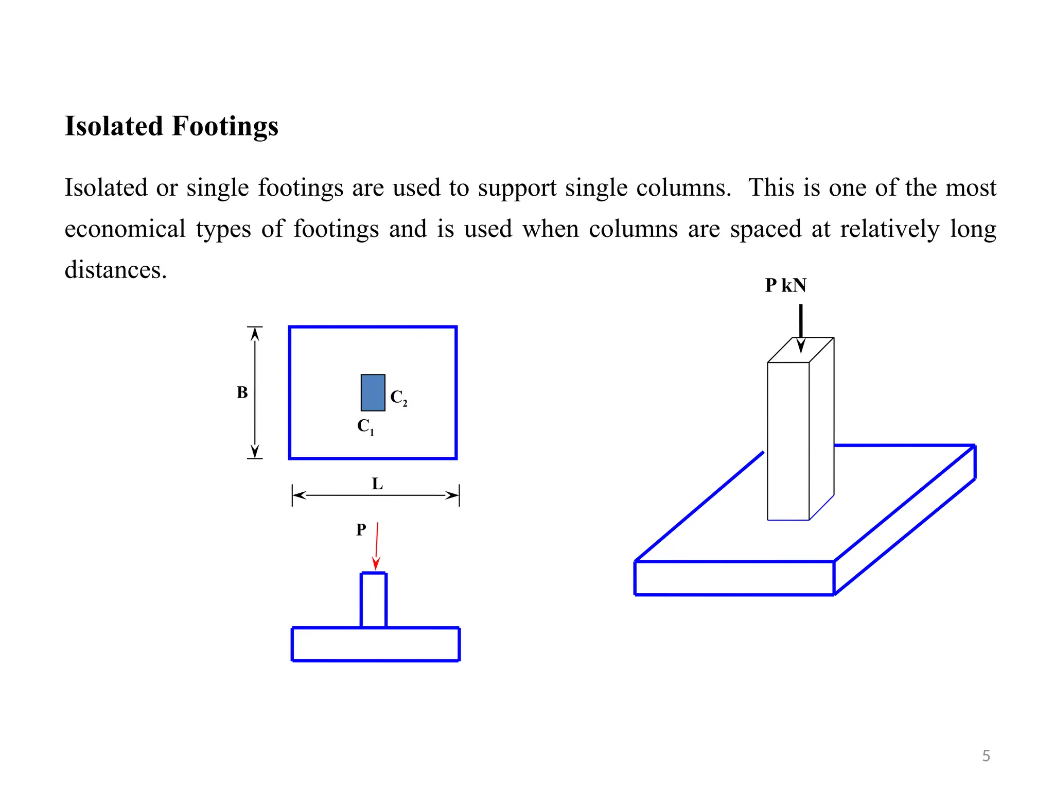
Isolated Footings
Isolated orsingle footings are used to support single columns. This is one of the most
economical types of footings and is used when columns are spaced at relatively long
distances.
P
L
B C2
C1
P kN
5
6.
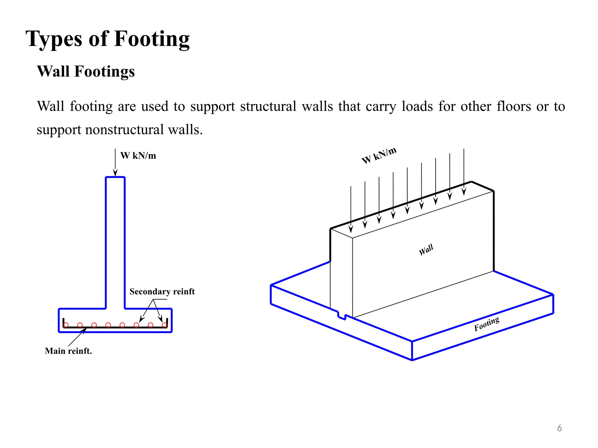
Types of Footing
WallFootings
Wall footing are used to support structural walls that carry loads for other floors or to
support nonstructural walls.
Wall
Footing
Main reinft.
Secondary reinft
W kN/m
W kN/m
6
7.
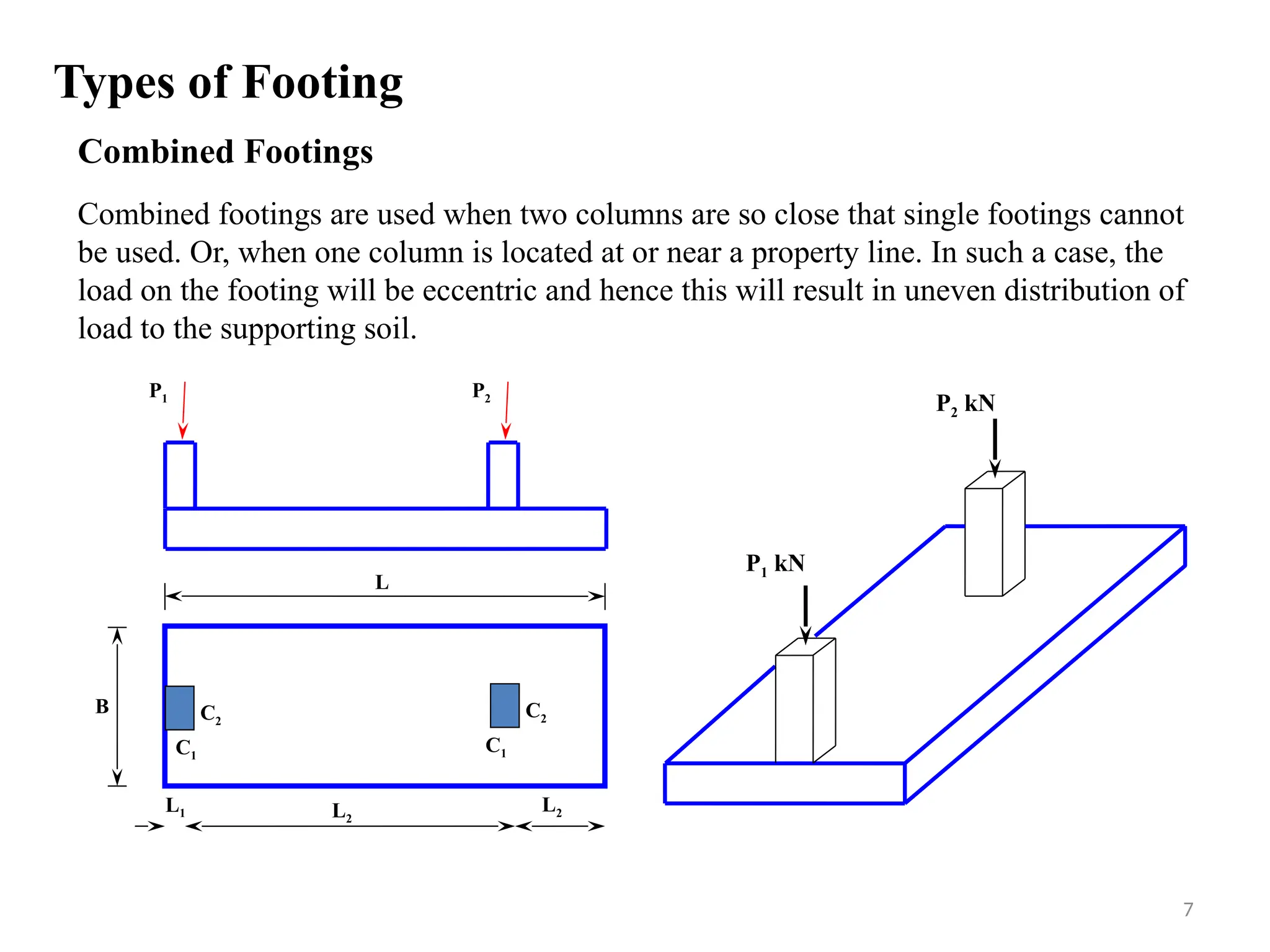
Combined Footings
Combined footingsare used when two columns are so close that single footings cannot
be used. Or, when one column is located at or near a property line. In such a case, the
load on the footing will be eccentric and hence this will result in uneven distribution of
load to the supporting soil.
P2
P1
P1 kN
P2 kN
C2
C1
C2
C1
L
B
L2
L1 L2
Types of Footing
7
8.
Combined Footings
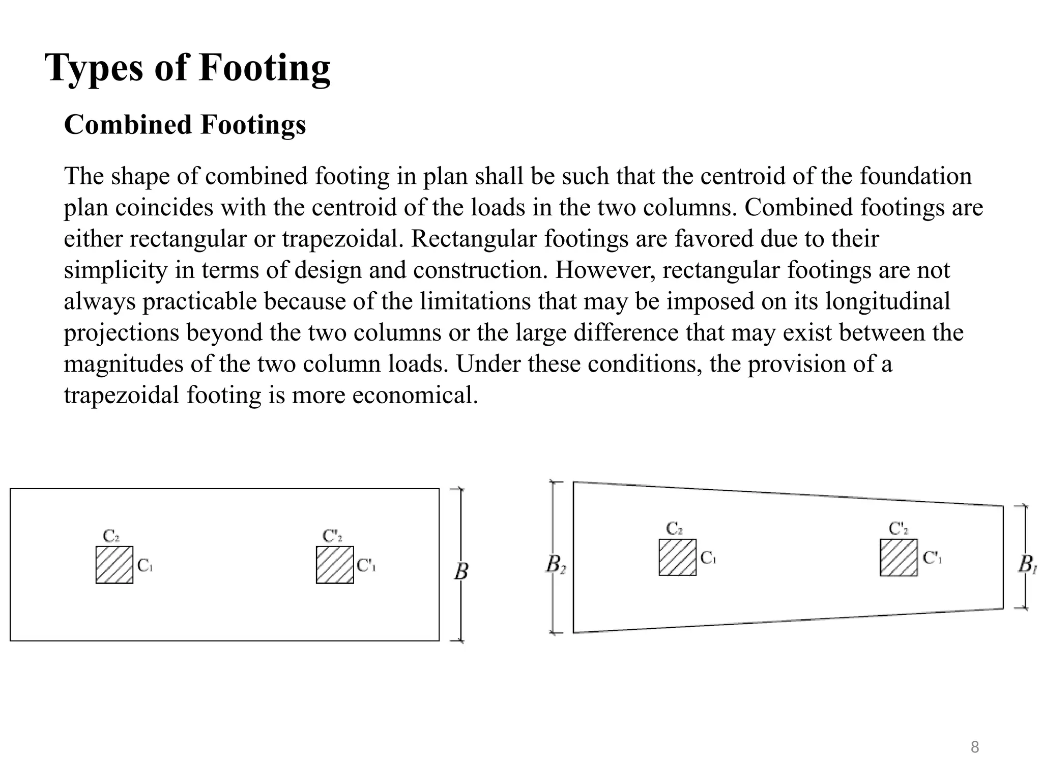
The shapeof combined footing in plan shall be such that the centroid of the foundation
plan coincides with the centroid of the loads in the two columns. Combined footings are
either rectangular or trapezoidal. Rectangular footings are favored due to their
simplicity in terms of design and construction. However, rectangular footings are not
always practicable because of the limitations that may be imposed on its longitudinal
projections beyond the two columns or the large difference that may exist between the
magnitudes of the two column loads. Under these conditions, the provision of a
trapezoidal footing is more economical.
Types of Footing
8
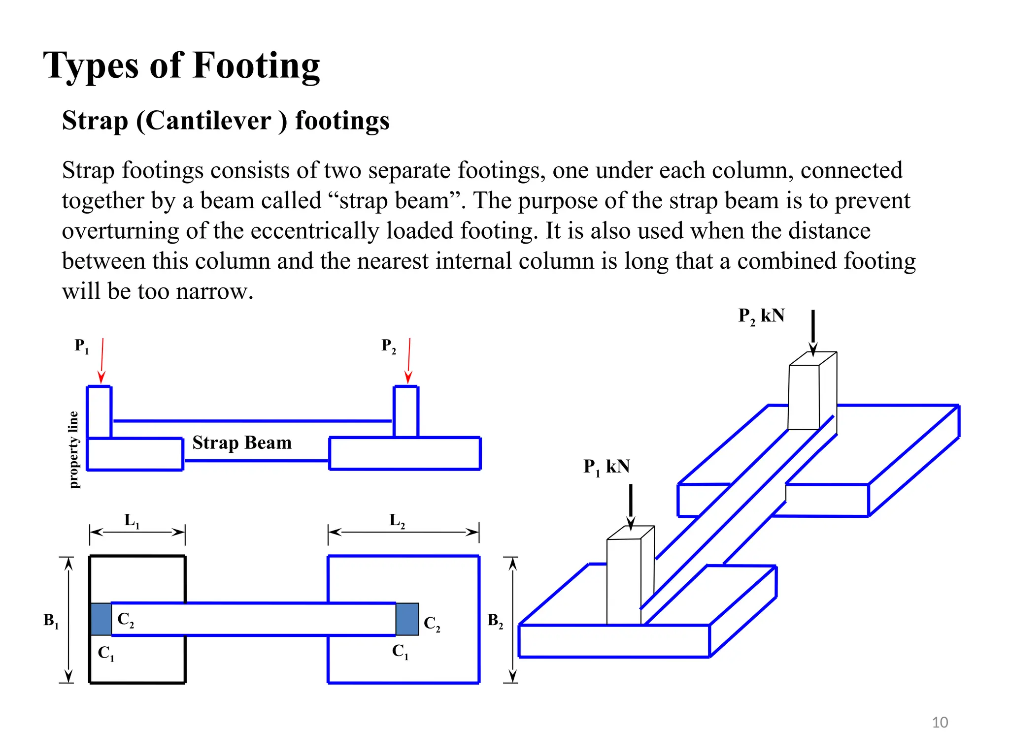
Strap (Cantilever )footings
Strap footings consists of two separate footings, one under each column, connected
together by a beam called “strap beam”. The purpose of the strap beam is to prevent
overturning of the eccentrically loaded footing. It is also used when the distance
between this column and the nearest internal column is long that a combined footing
will be too narrow.
P2
P1
P1 kN
C2
C1
C2
C1
B1
P2 kN
B2
L1 L2
Strap Beam
property
line
Types of Footing
10
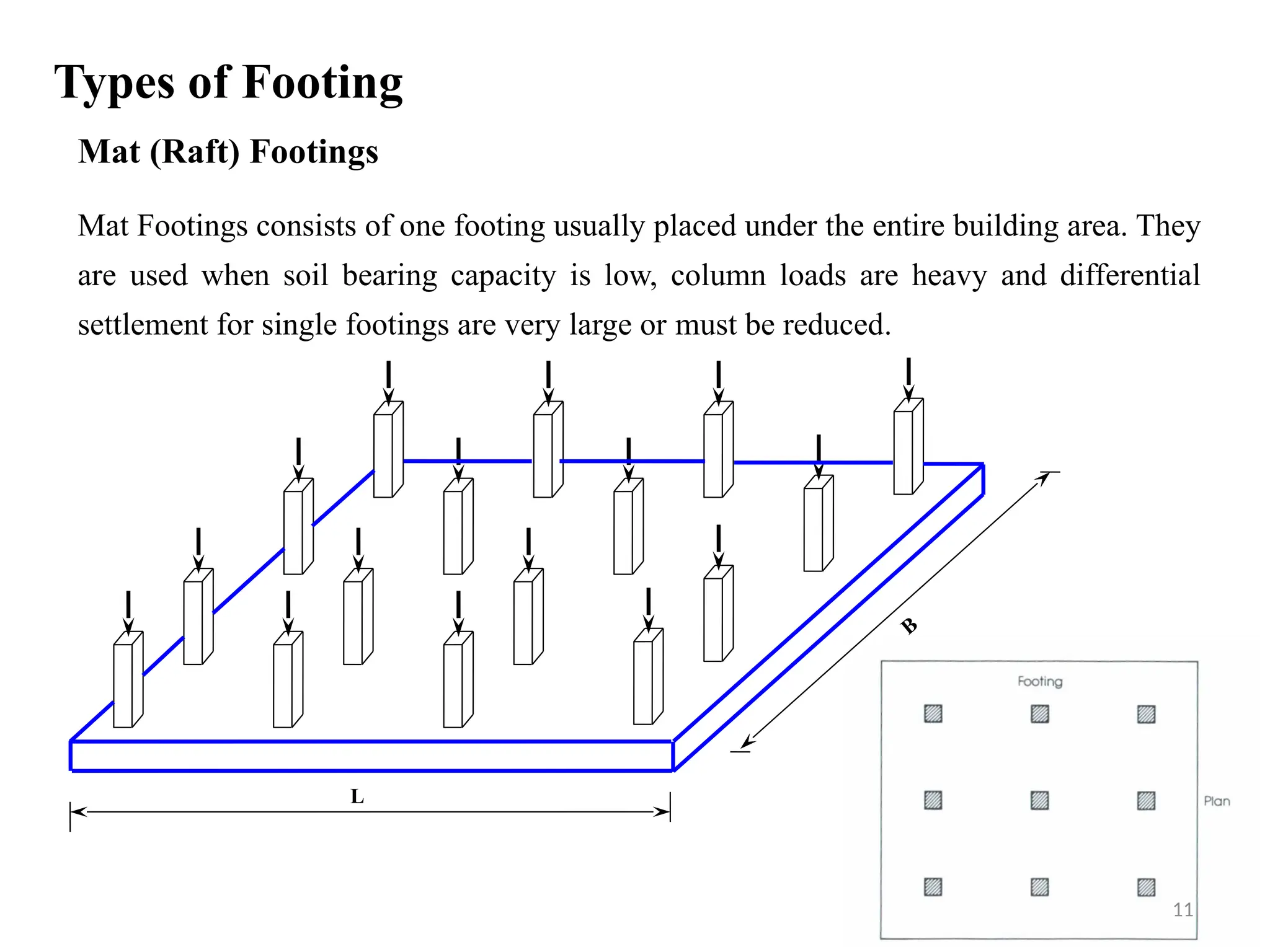
11.
Mat (Raft) Footings
MatFootings consists of one footing usually placed under the entire building area. They
are used when soil bearing capacity is low, column loads are heavy and differential
settlement for single footings are very large or must be reduced.
L
B
Types of Footing
11
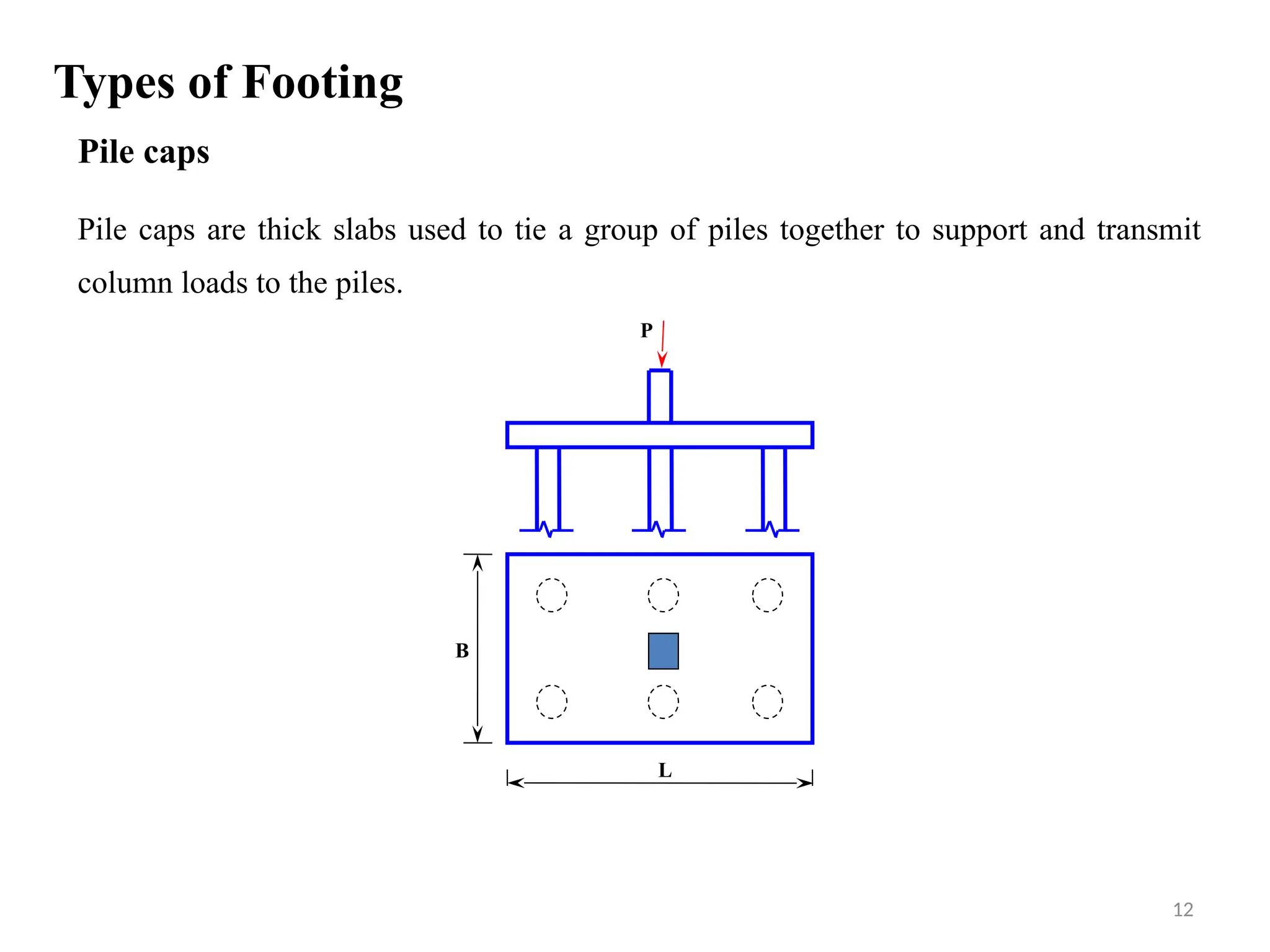
12.
Pile caps
Pile capsare thick slabs used to tie a group of piles together to support and transmit
column loads to the piles.
P
L
B
Types of Footing
12
13.
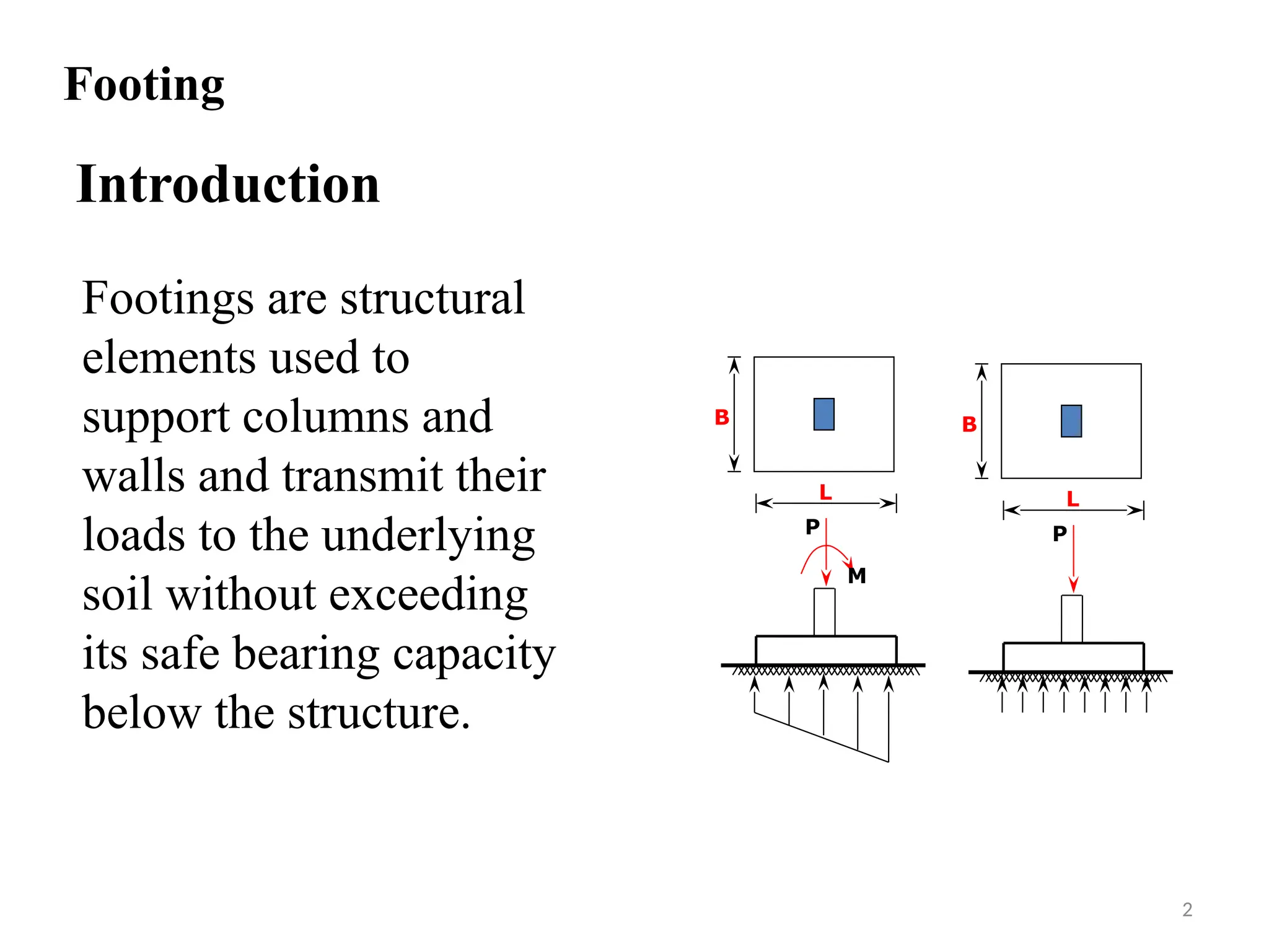
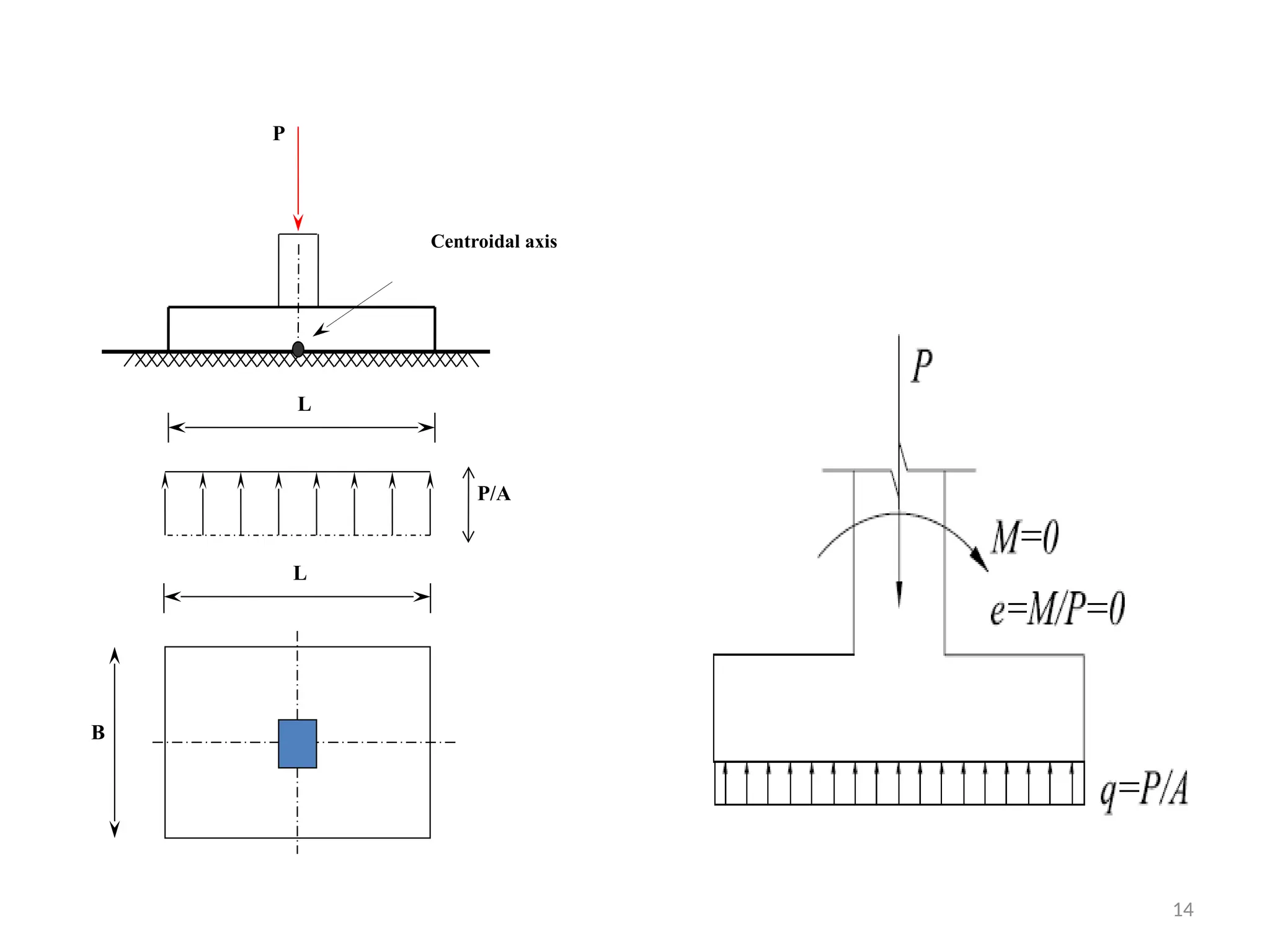
Concentrically loaded Footings
•If the resultant of the loads acting at the base
of the footing coincides with the centroid of
the footing area, the footing is concentrically
loaded and a uniform distribution of soil
pressure is assumed in design, as shown in the
figure
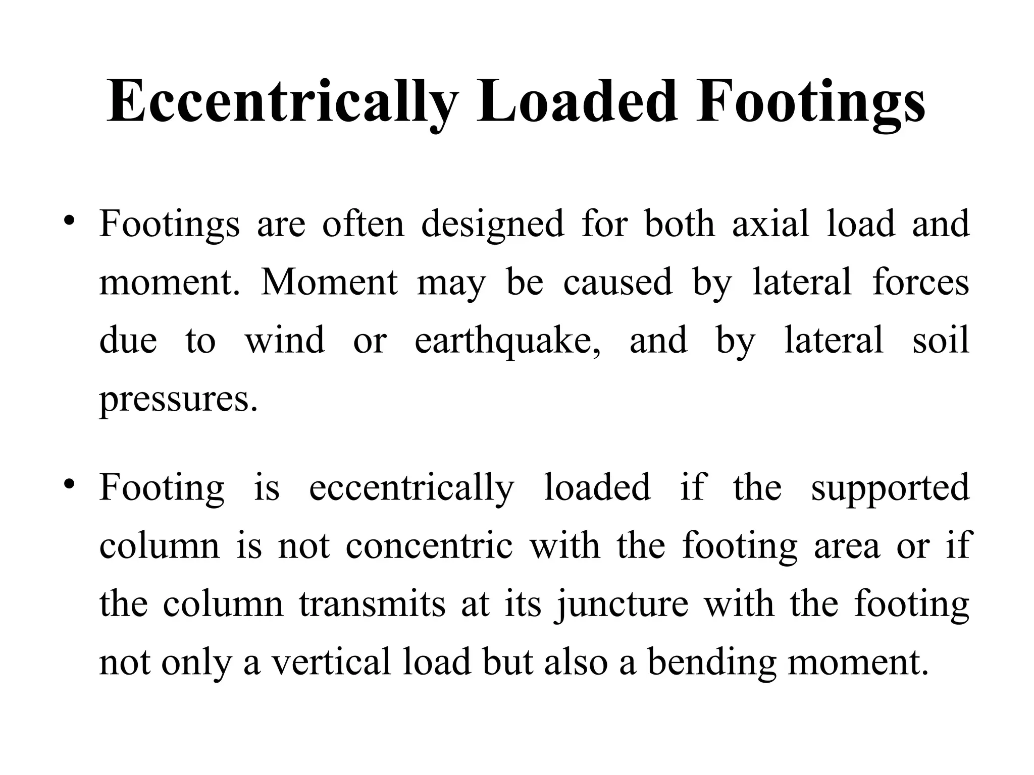
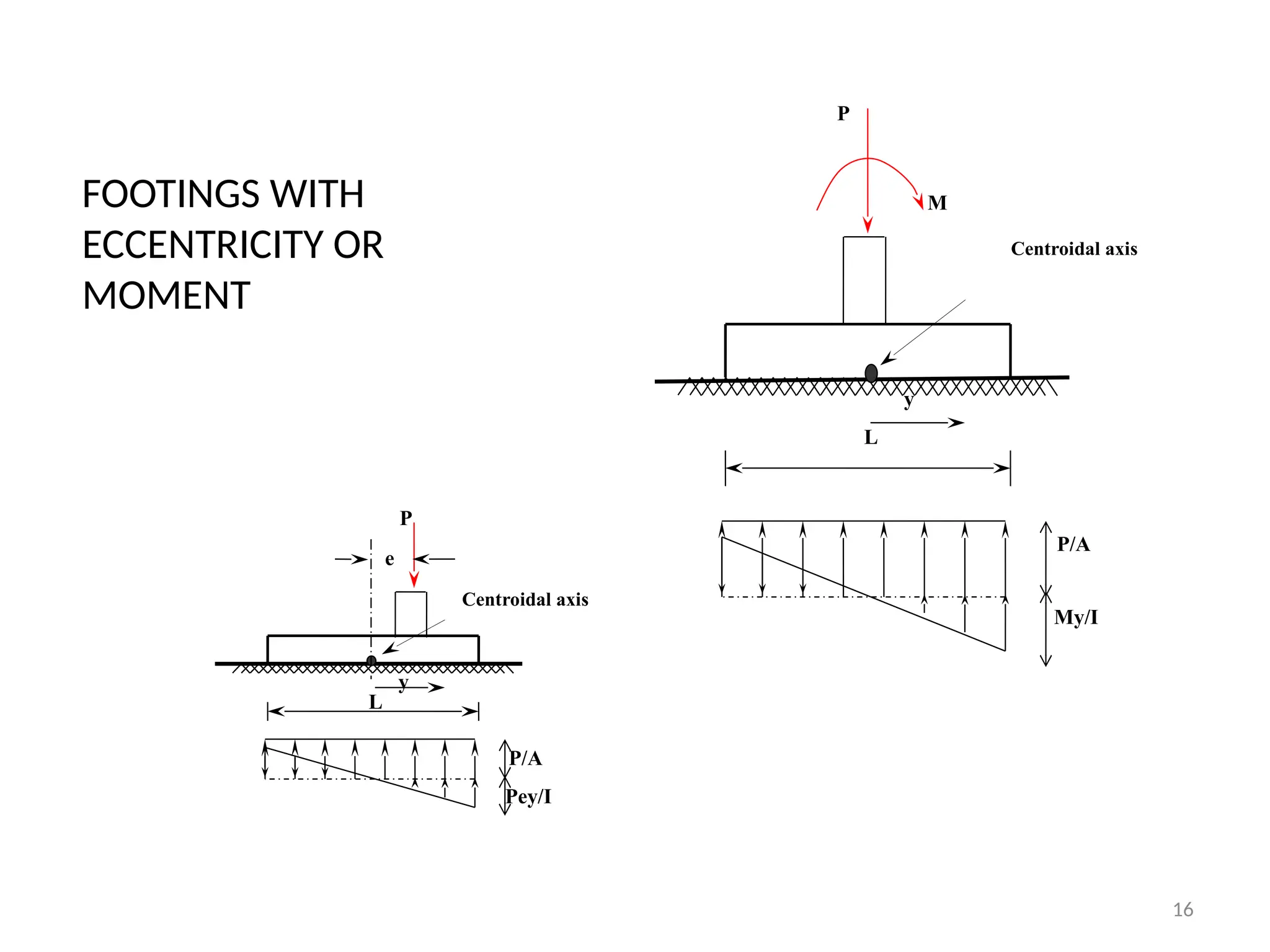
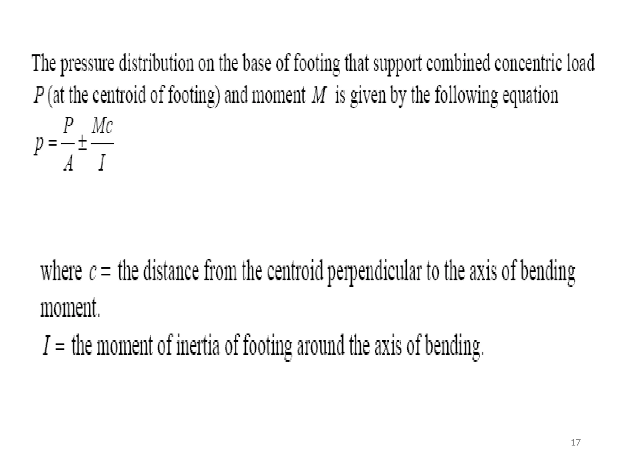
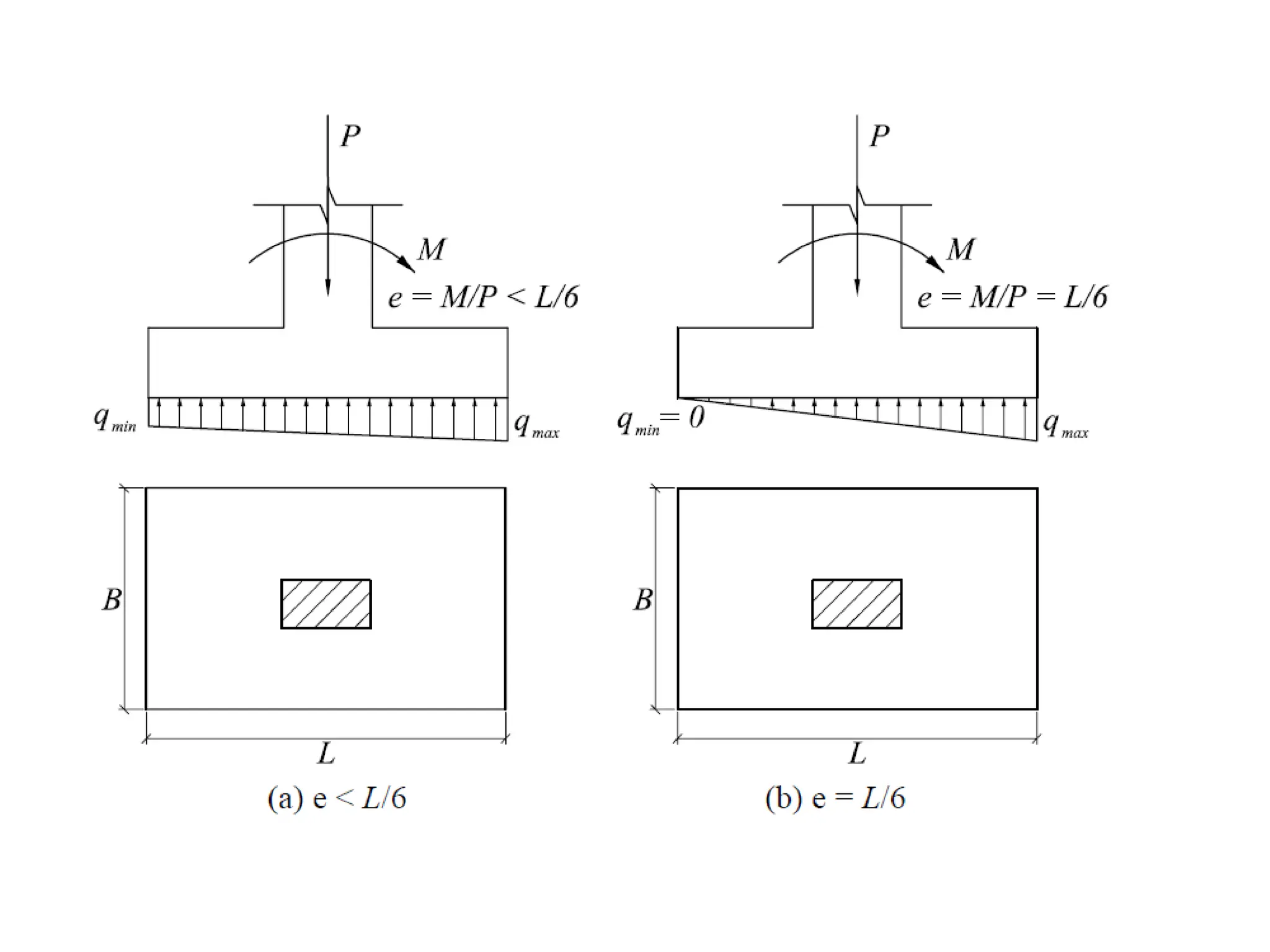
Eccentrically Loaded Footings
•Footings are often designed for both axial load and
moment. Moment may be caused by lateral forces
due to wind or earthquake, and by lateral soil
pressures.
• Footing is eccentrically loaded if the supported
column is not concentric with the footing area or if
the column transmits at its juncture with the footing
not only a vertical load but also a bending moment.
19
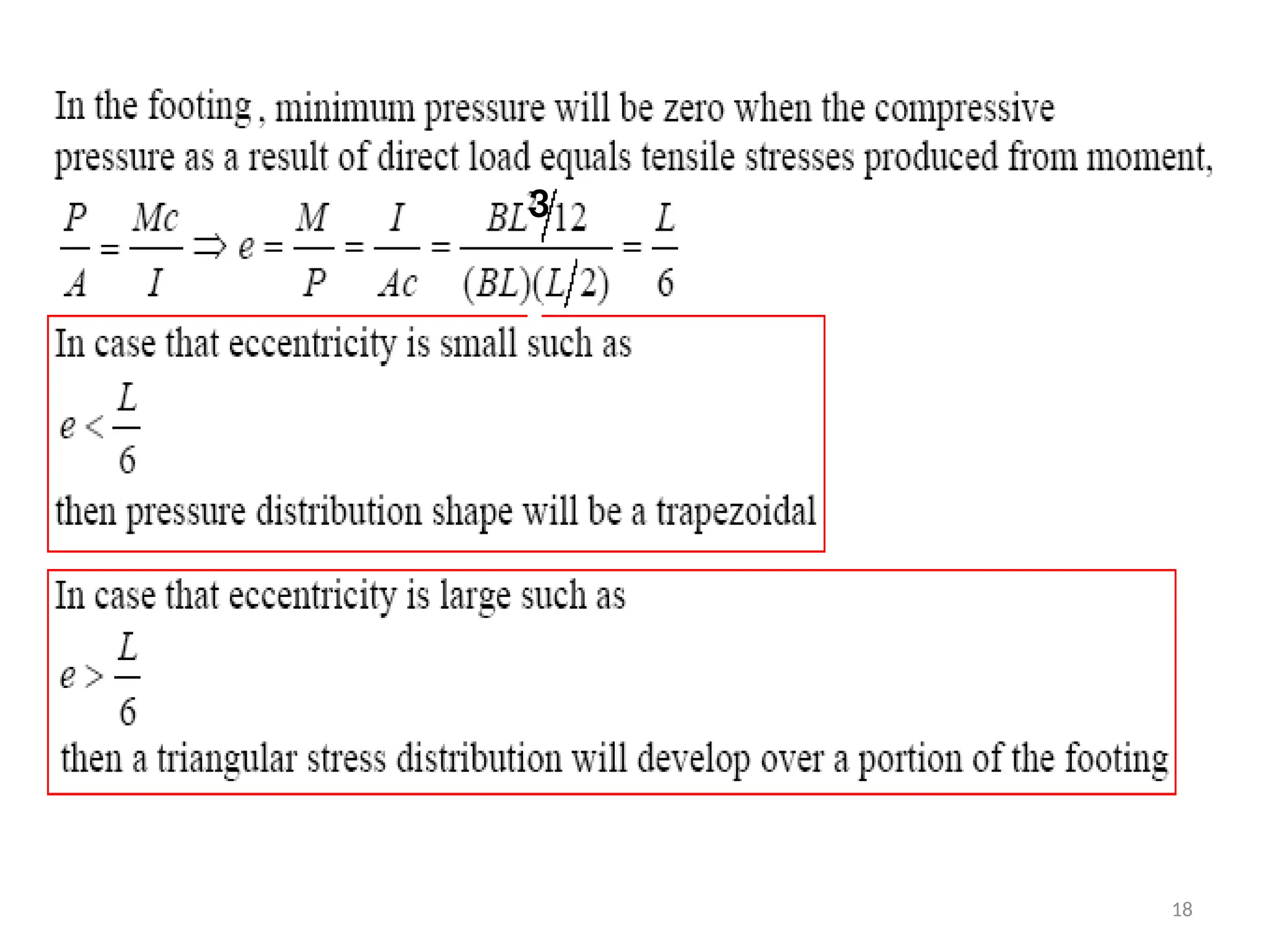
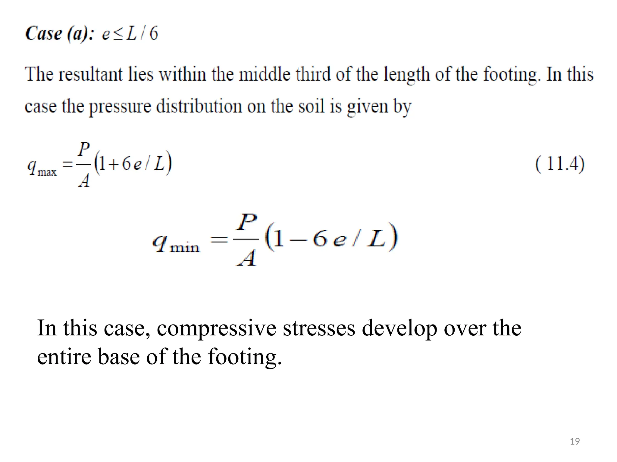
In this case,compressive stresses develop over the
entire base of the footing.
21.
21
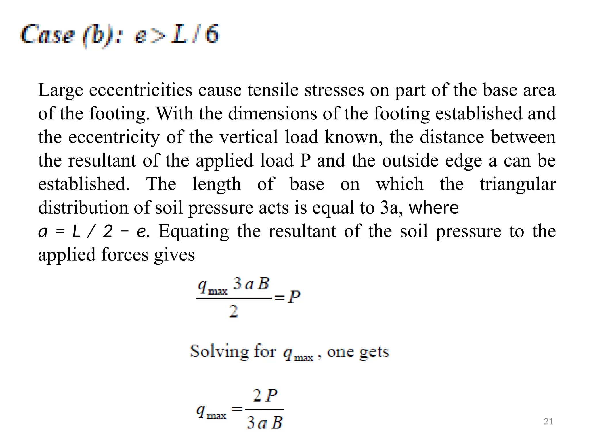
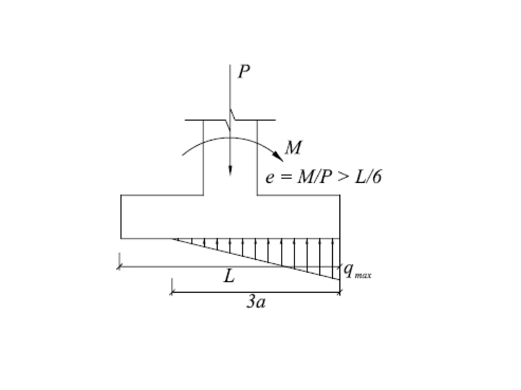
Large eccentricities causetensile stresses on part of the base area
of the footing. With the dimensions of the footing established and
the eccentricity of the vertical load known, the distance between
the resultant of the applied load P and the outside edge a can be
established. The length of base on which the triangular
distribution of soil pressure acts is equal to 3a, where
a = L / 2 − e. Equating the resultant of the soil pressure to the
applied forces gives
24
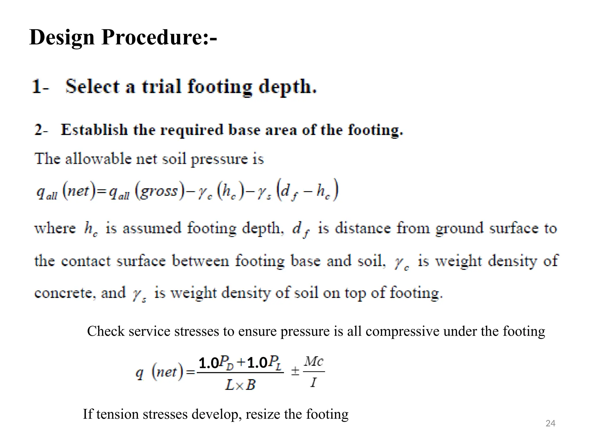
Design Procedure:-
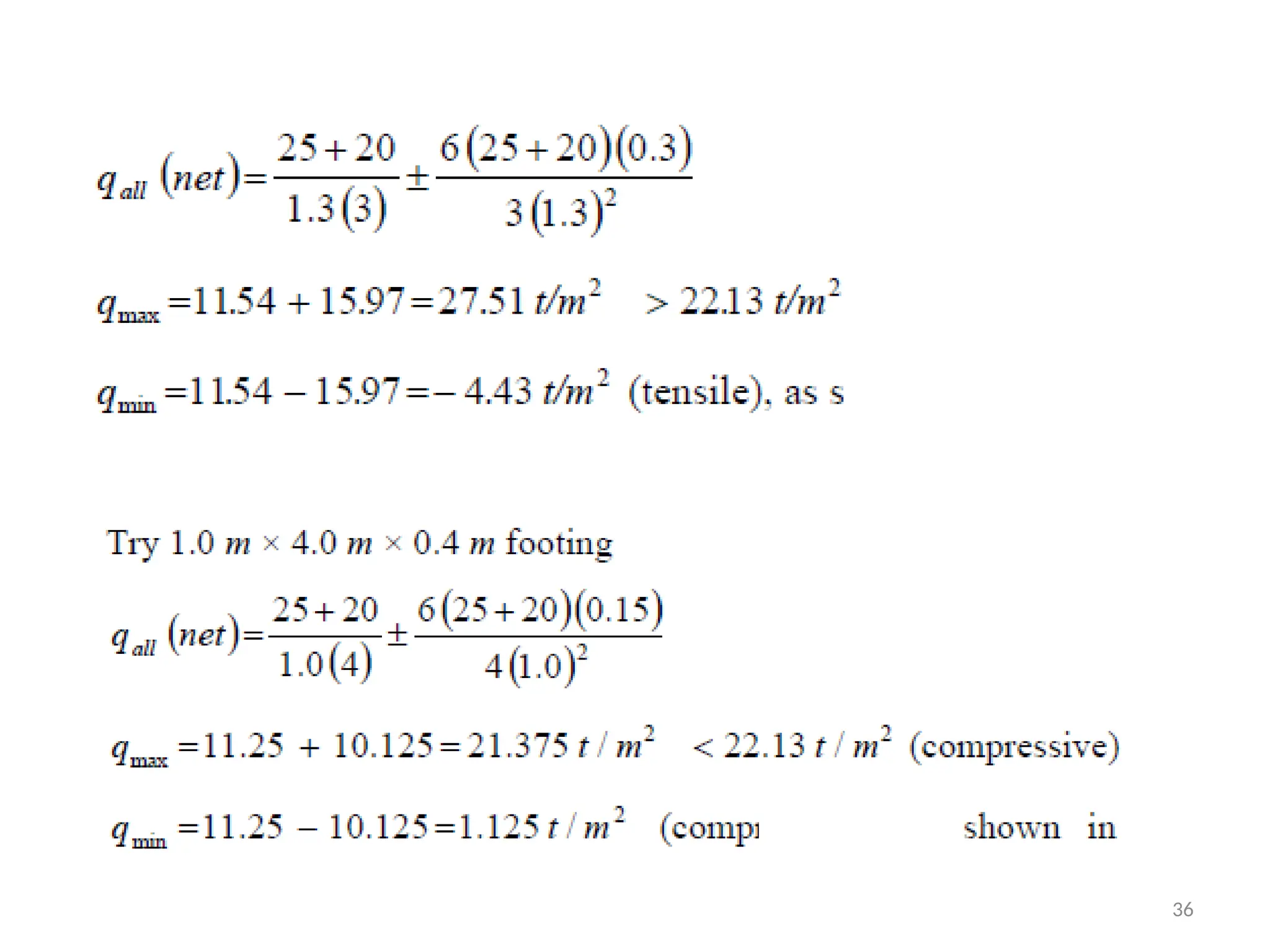
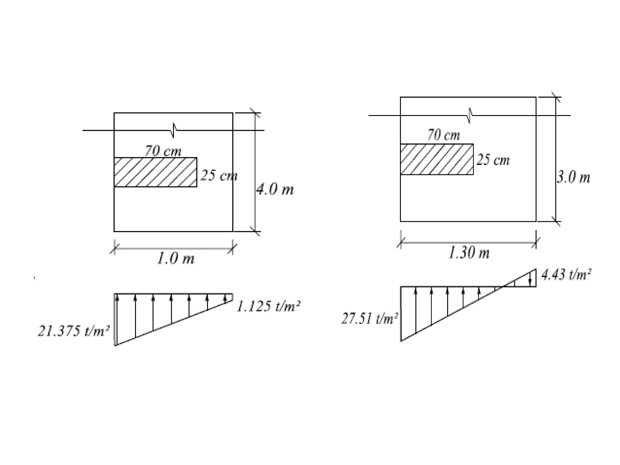
1.0 1.0
Checkservice stresses to ensure pressure is all compressive under the footing
If tension stresses develop, resize the footing
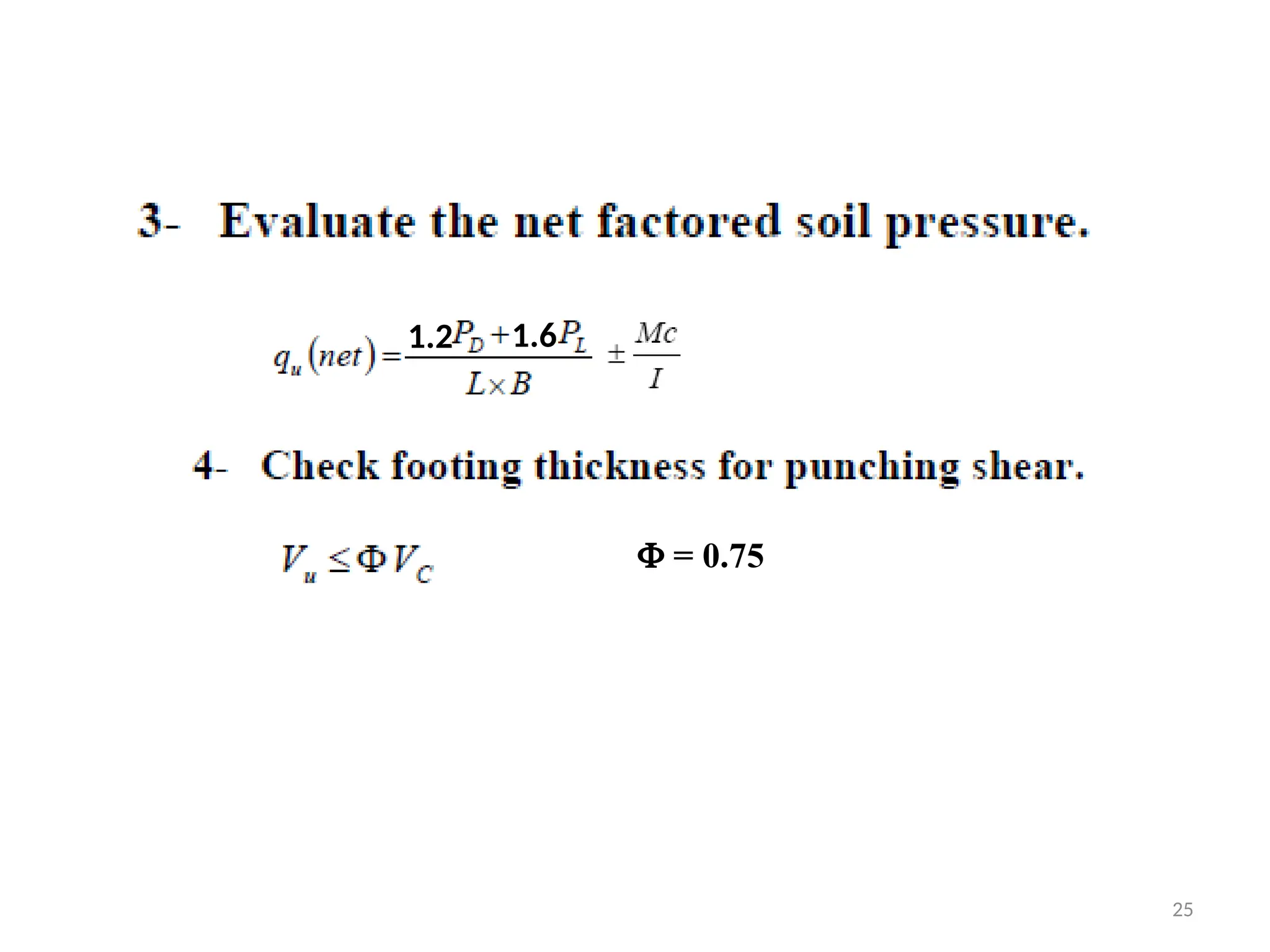
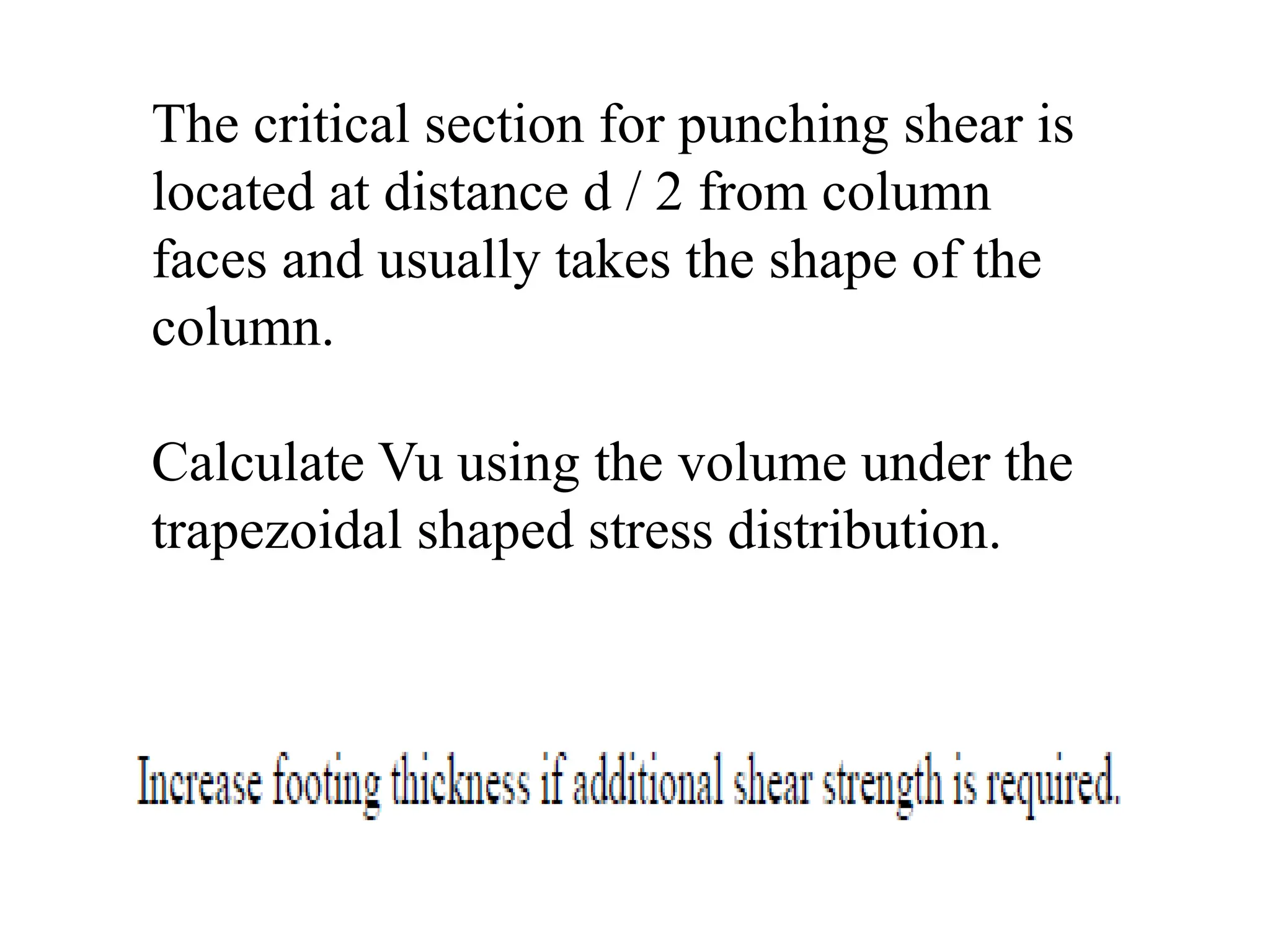
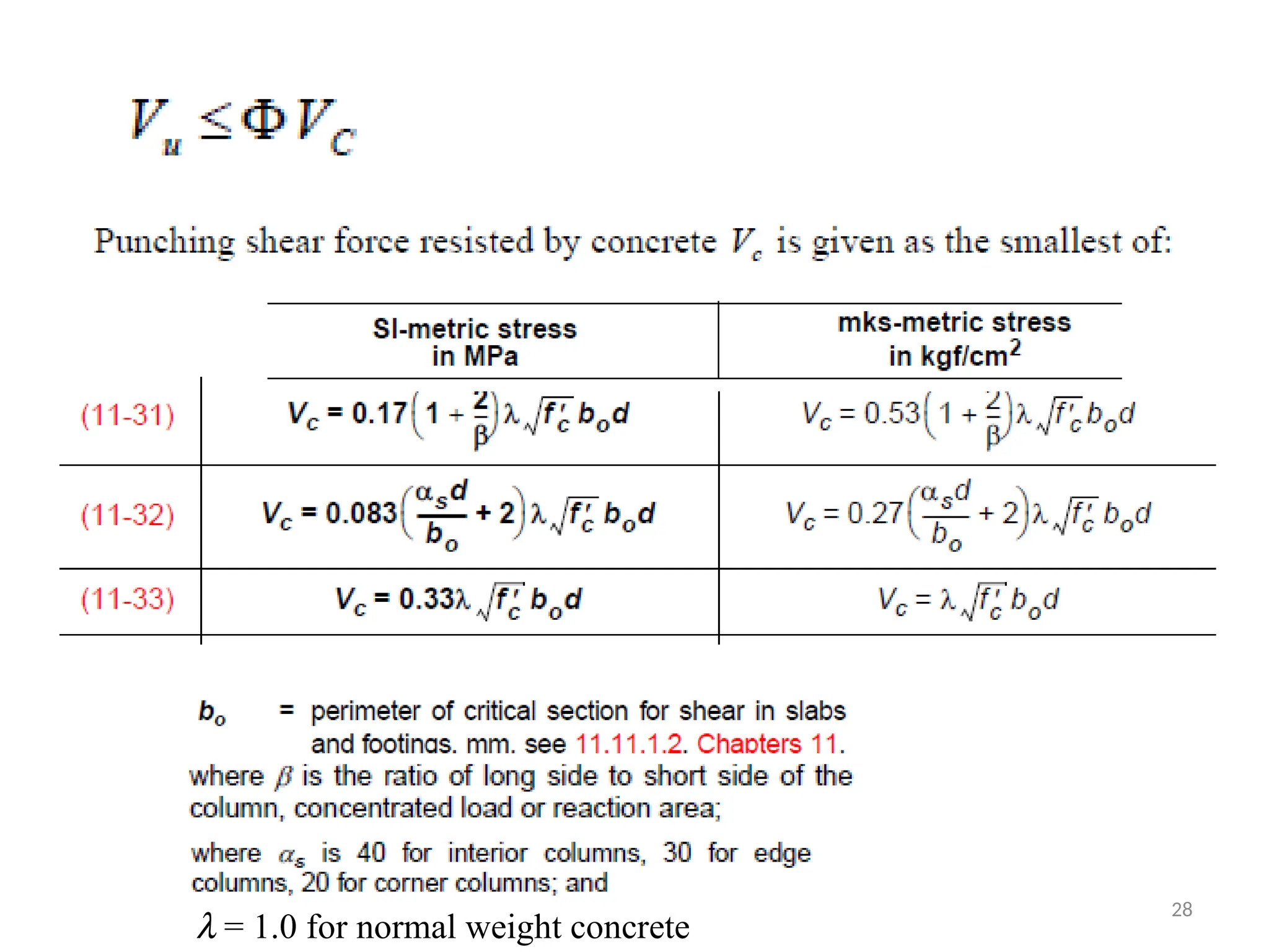
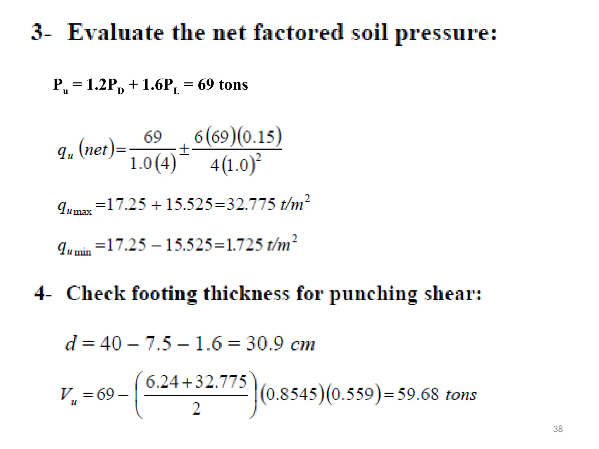
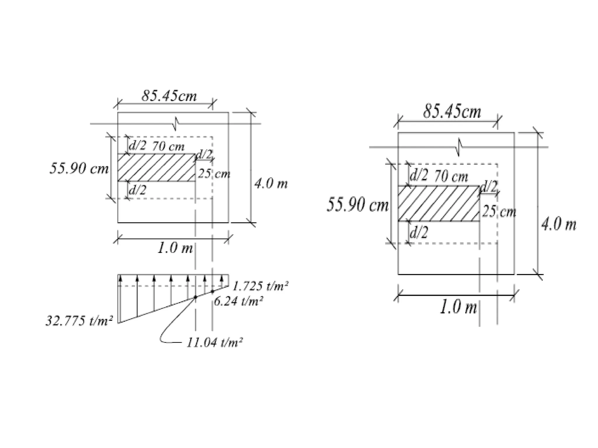
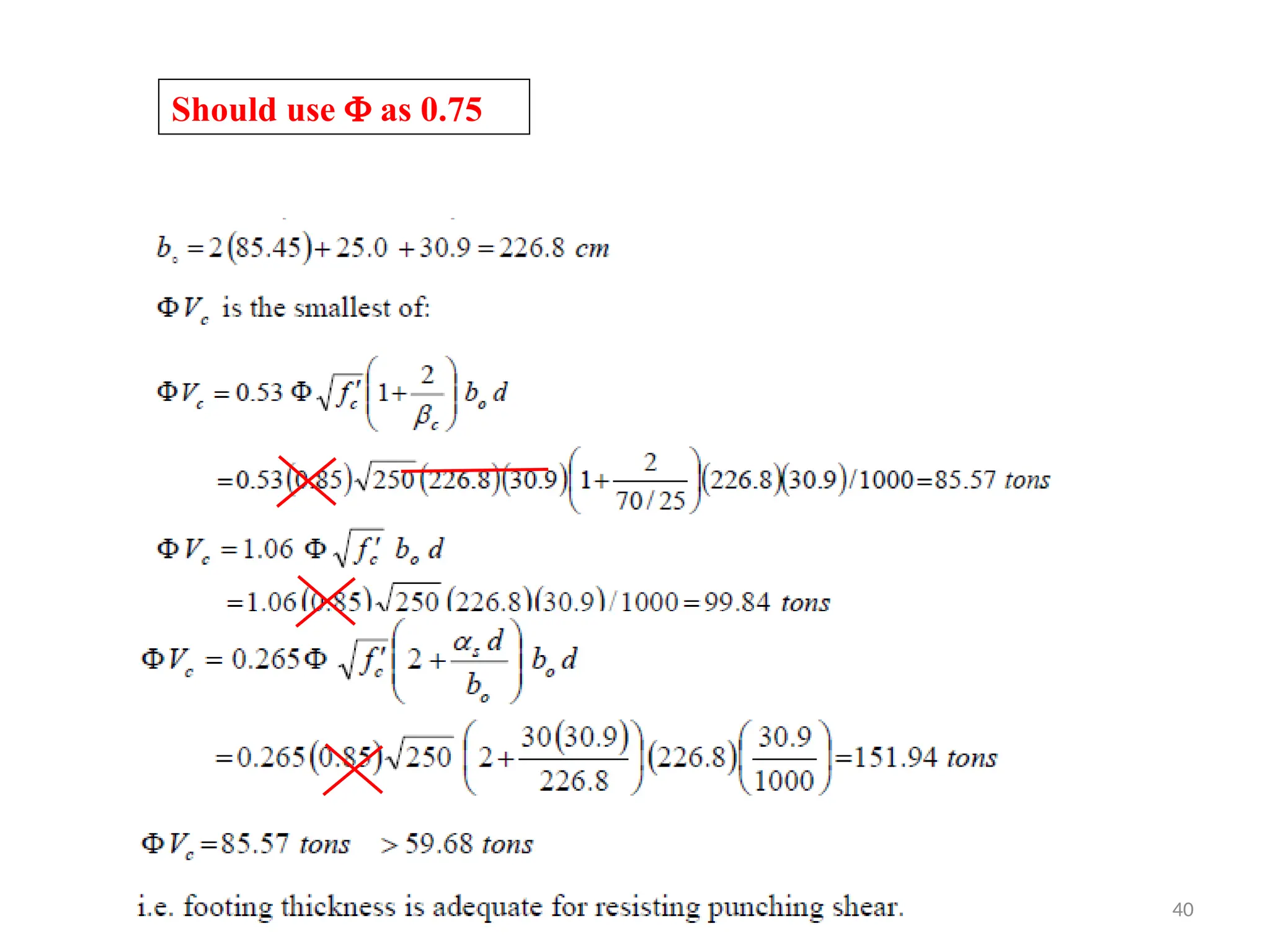
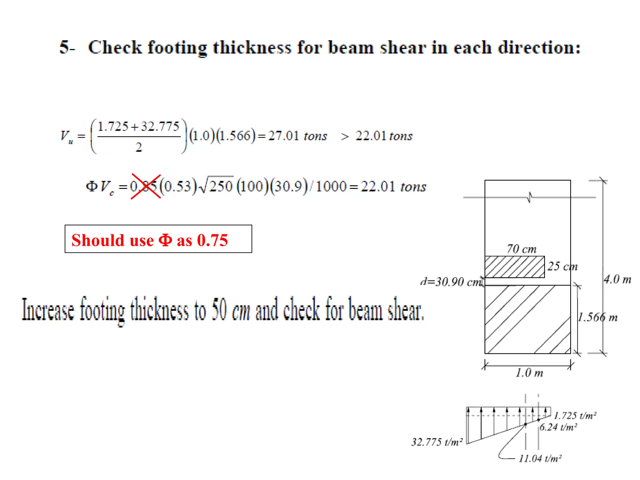
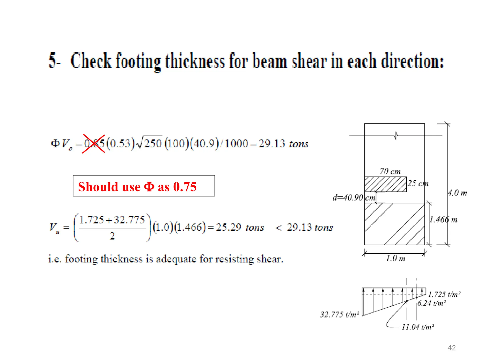
The critical sectionfor punching shear is
located at distance d / 2 from column
faces and usually takes the shape of the
column.
Calculate Vu using the volume under the
trapezoidal shaped stress distribution.
27.
27
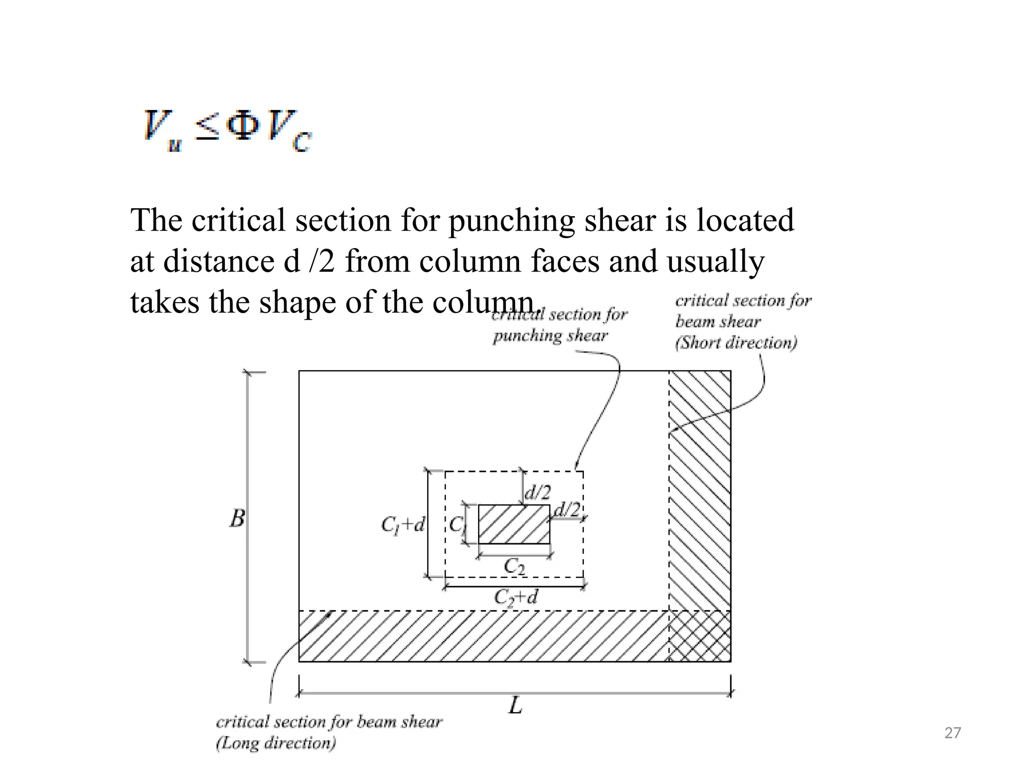
The critical sectionfor punching shear is located
at distance d /2 from column faces and usually
takes the shape of the column.
32
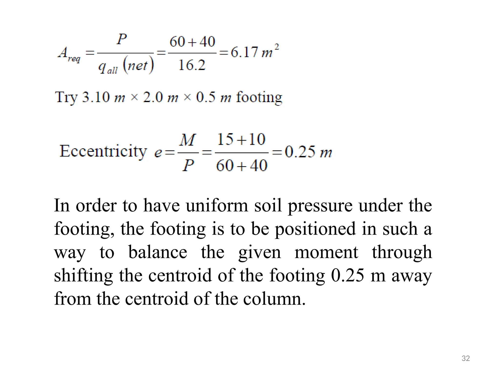
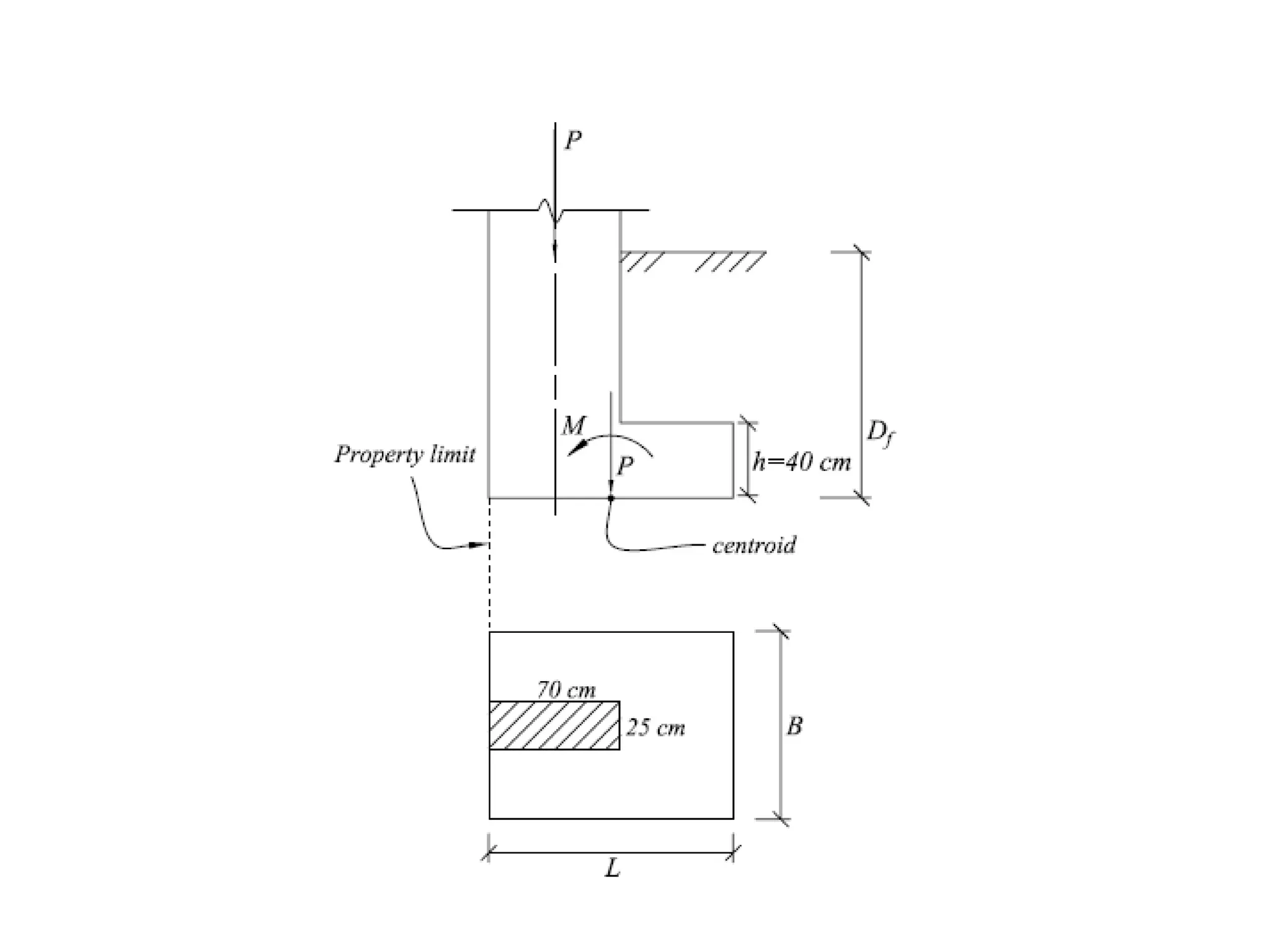
In order tohave uniform soil pressure under the
footing, the footing is to be positioned in such a
way to balance the given moment through
shifting the centroid of the footing 0.25 m away
from the centroid of the column.
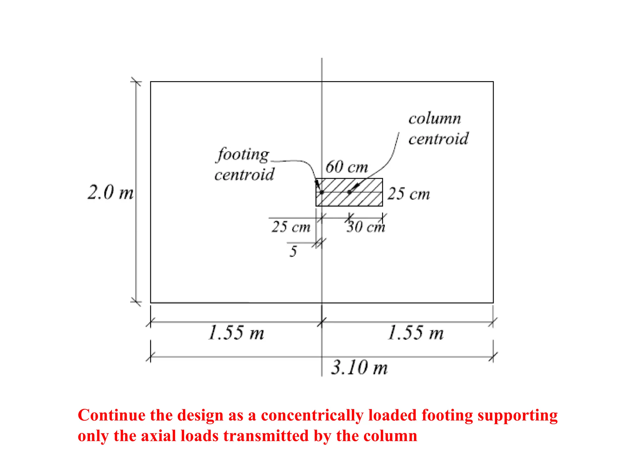
33.
Continue the designas a concentrically loaded footing supporting
only the axial loads transmitted by the column