Download as PDF, PPTX
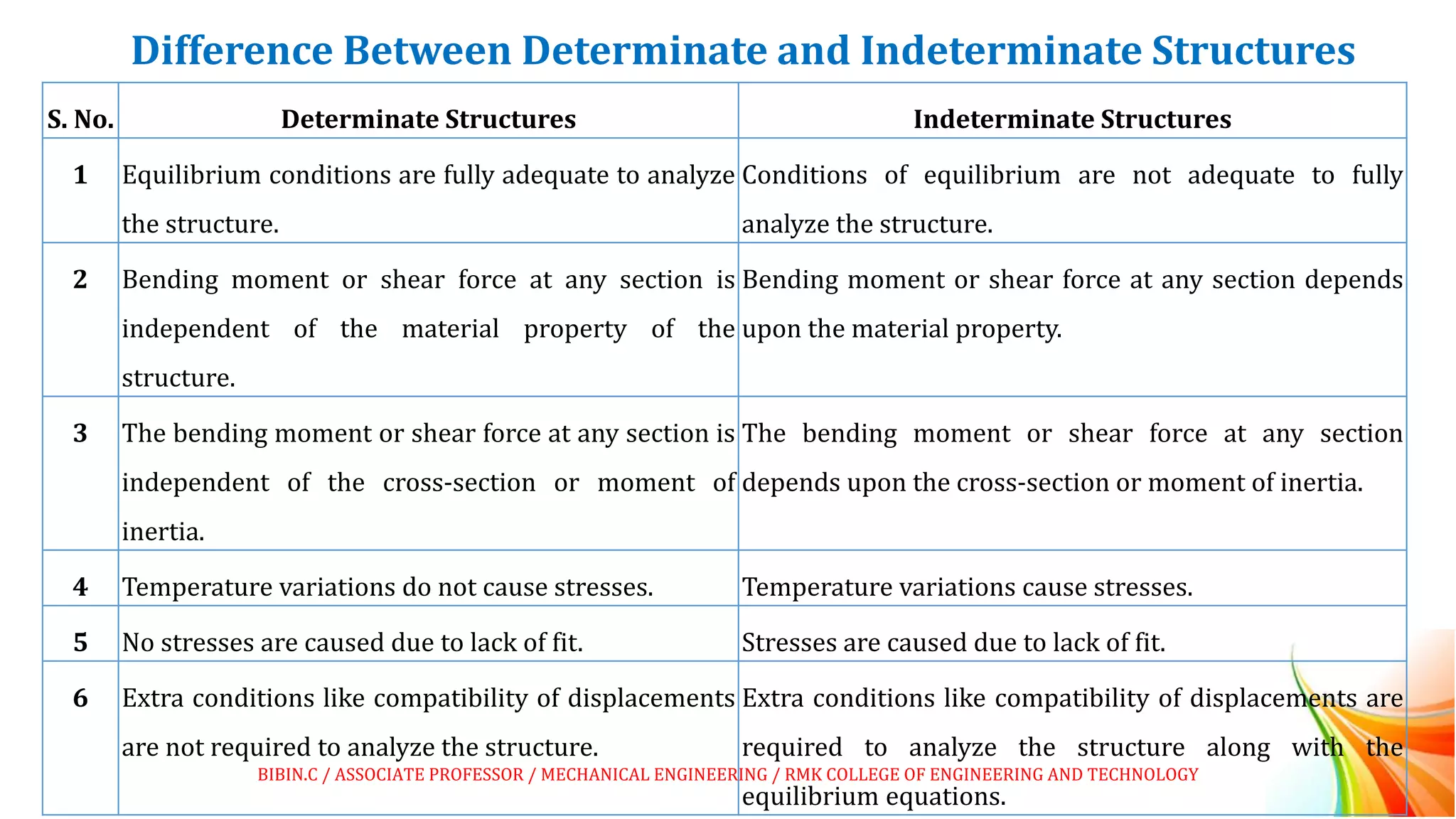
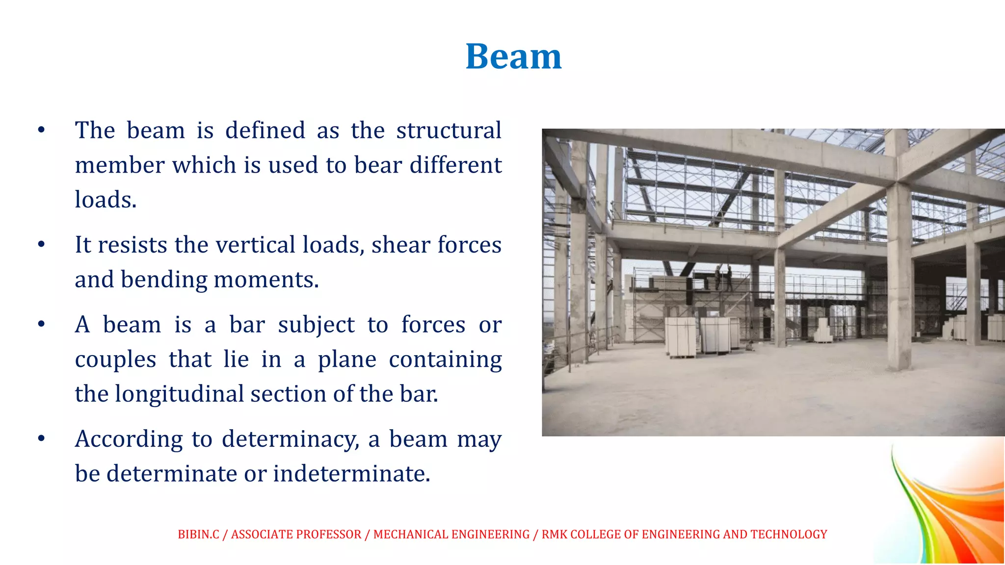
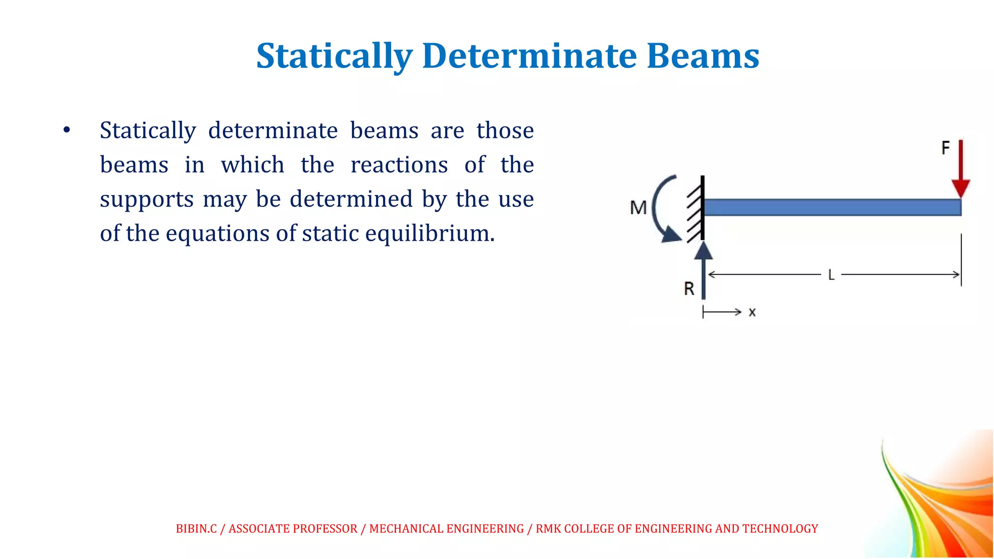
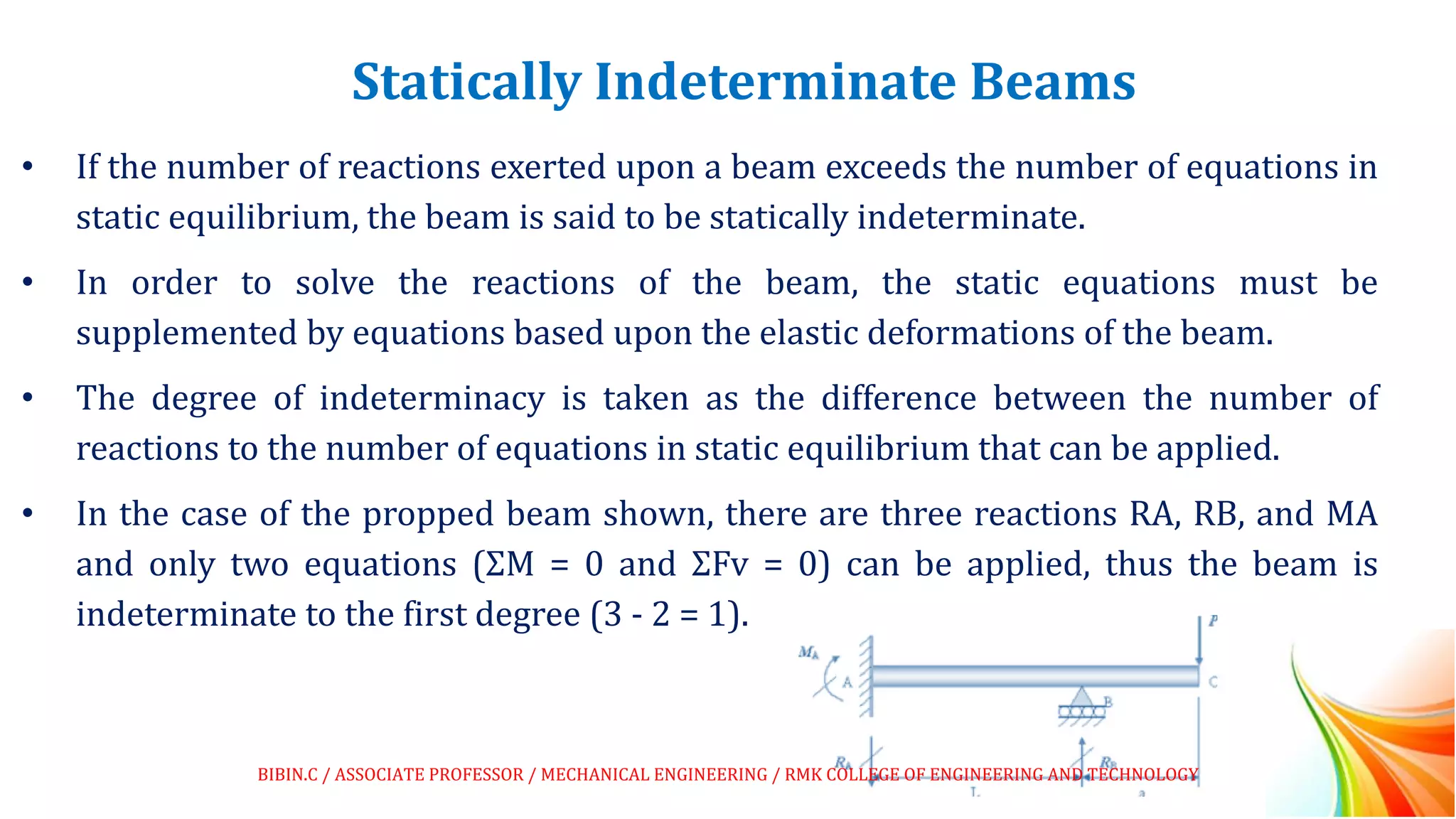
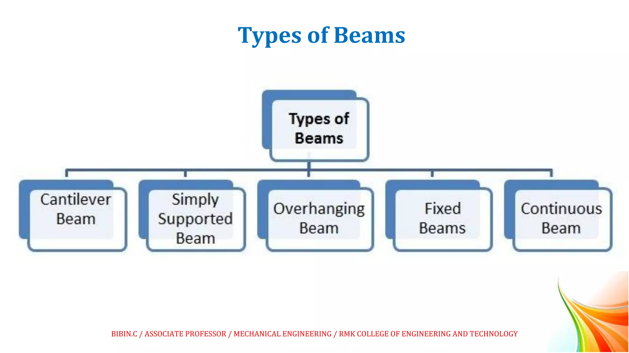
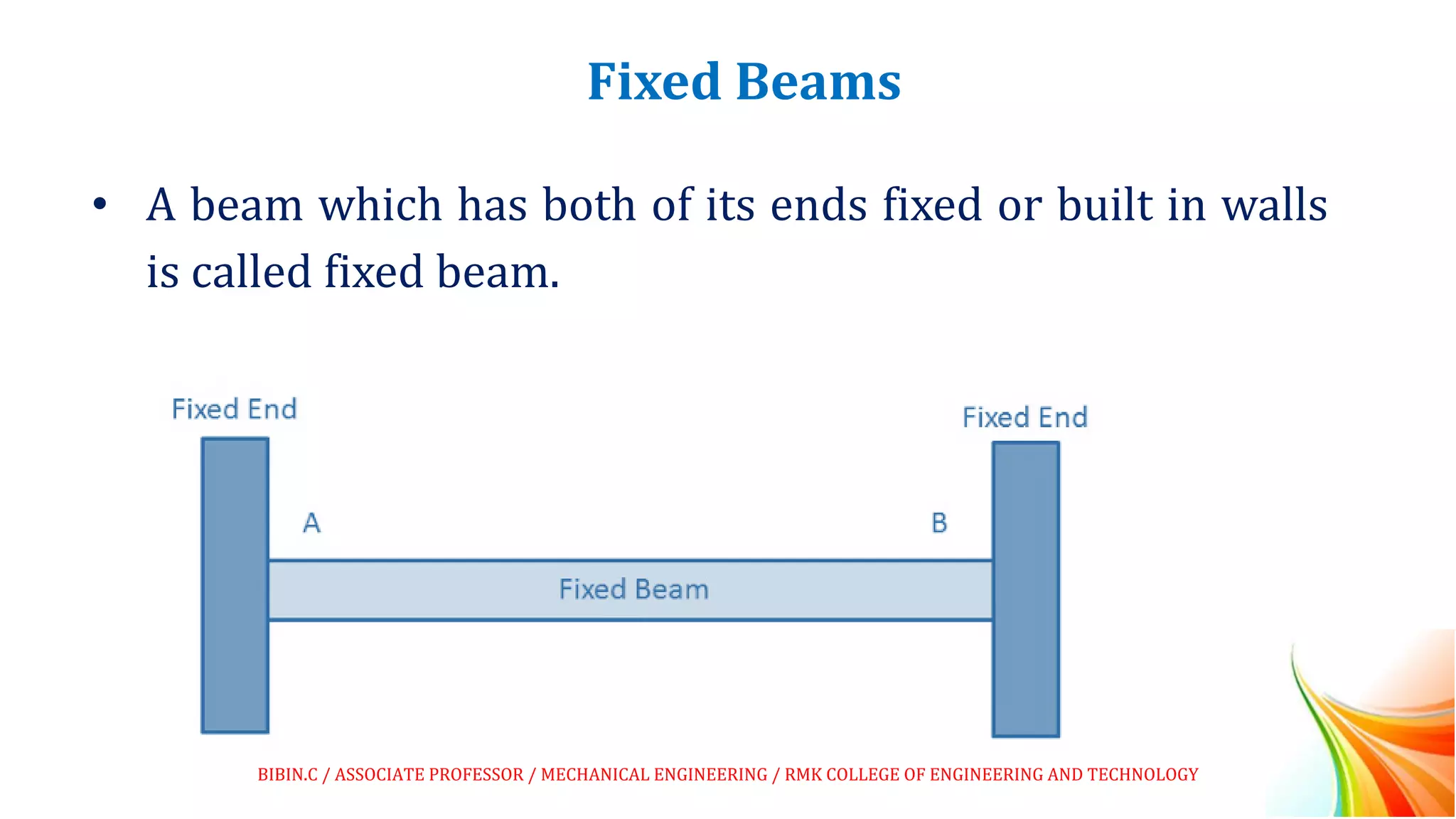
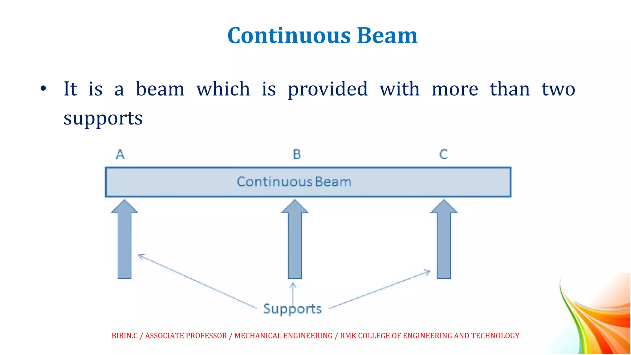
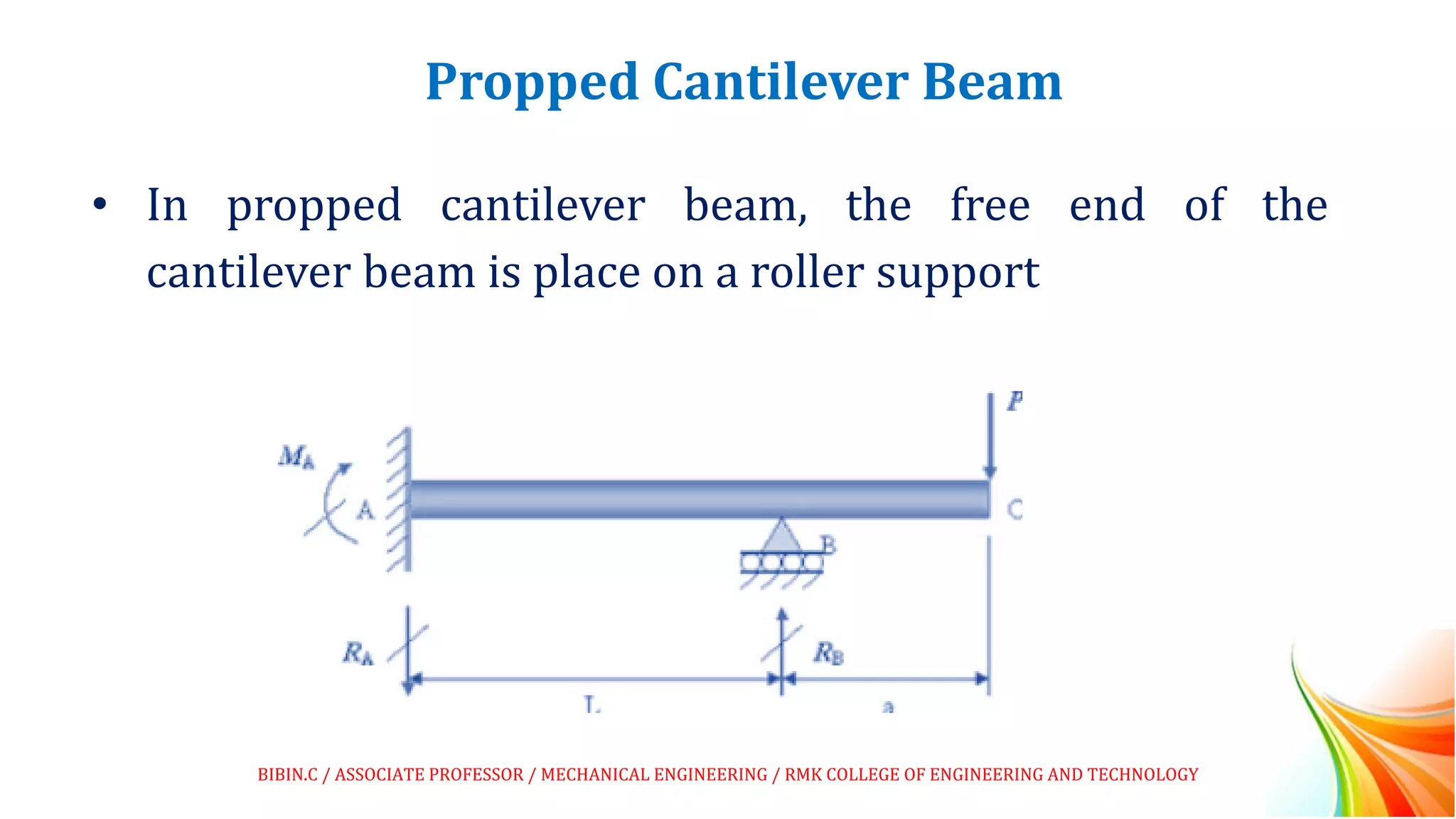
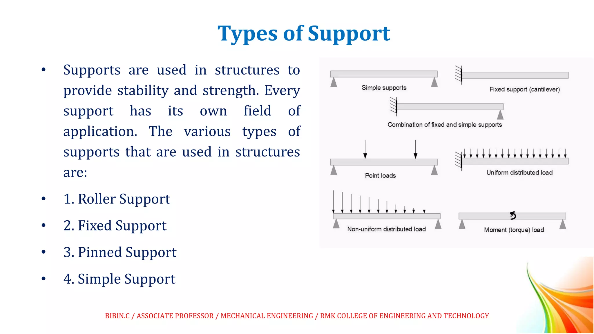
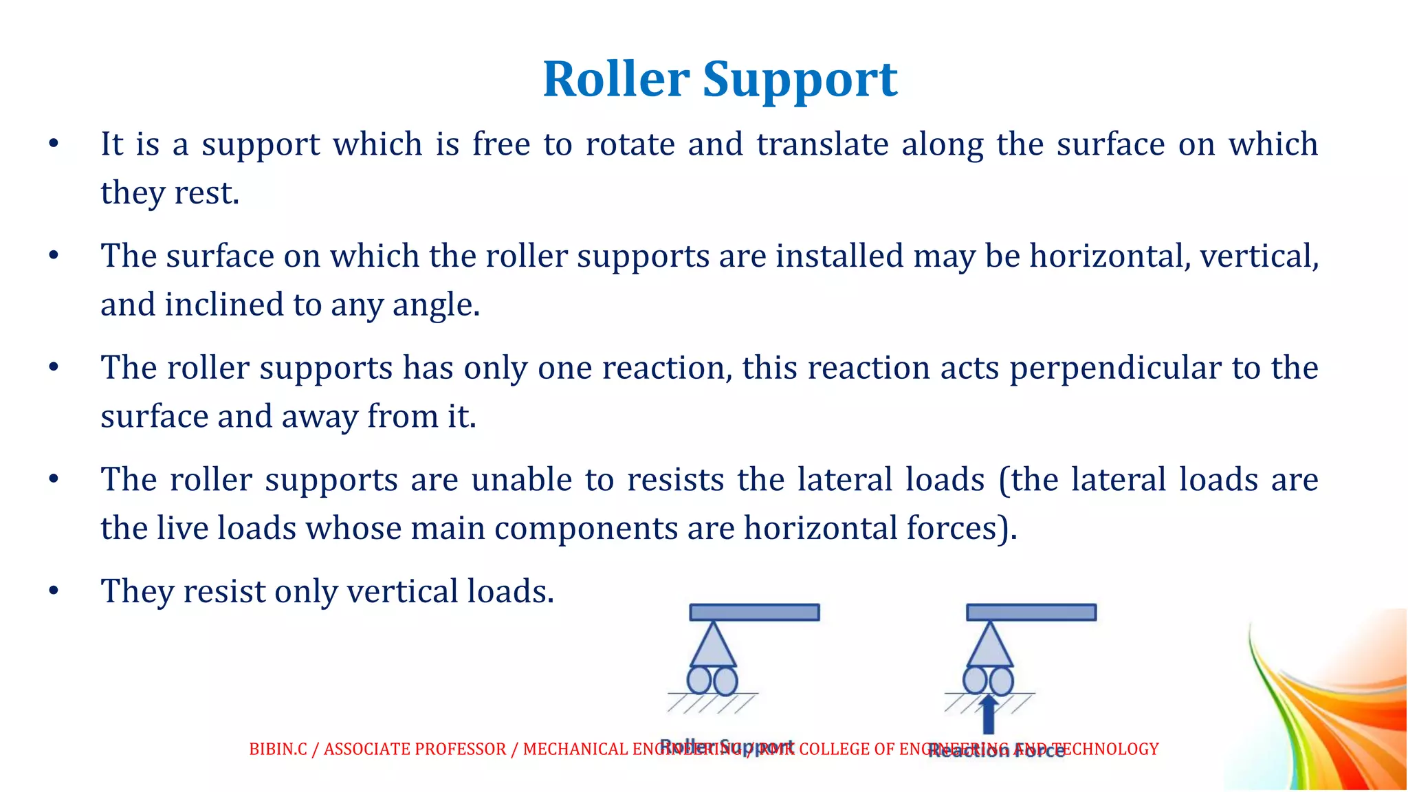
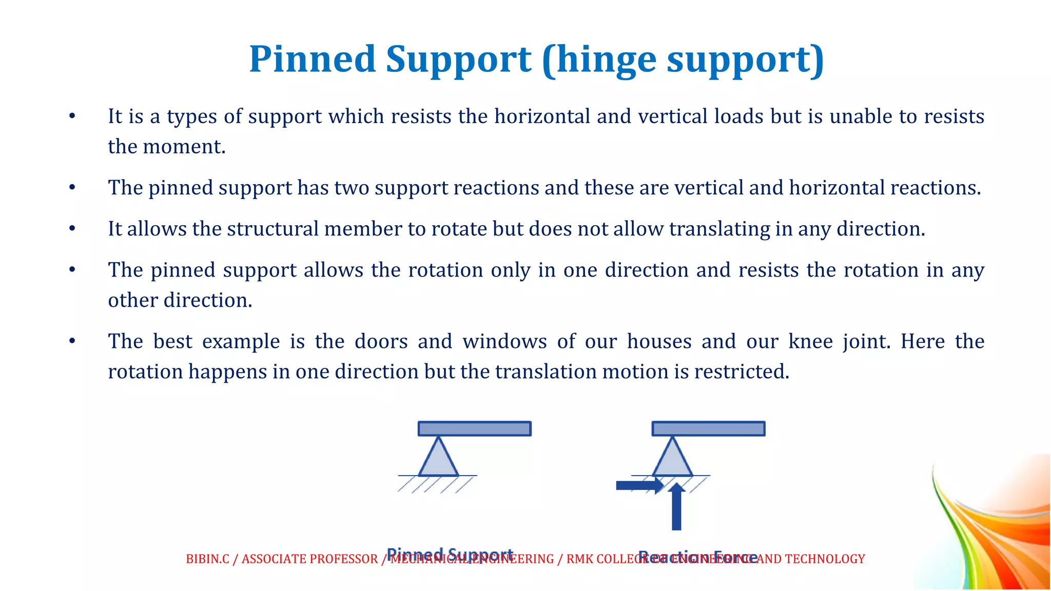
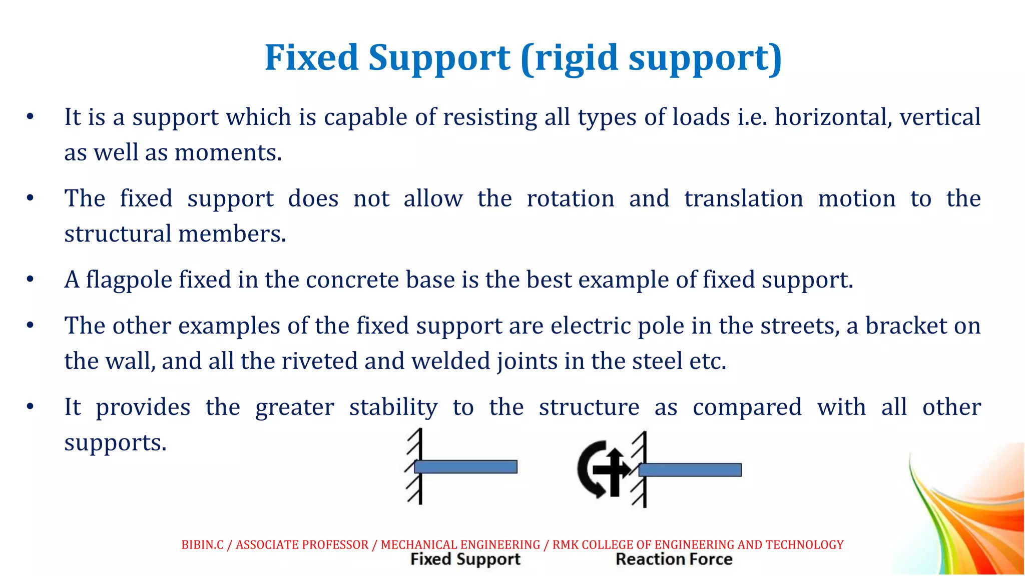
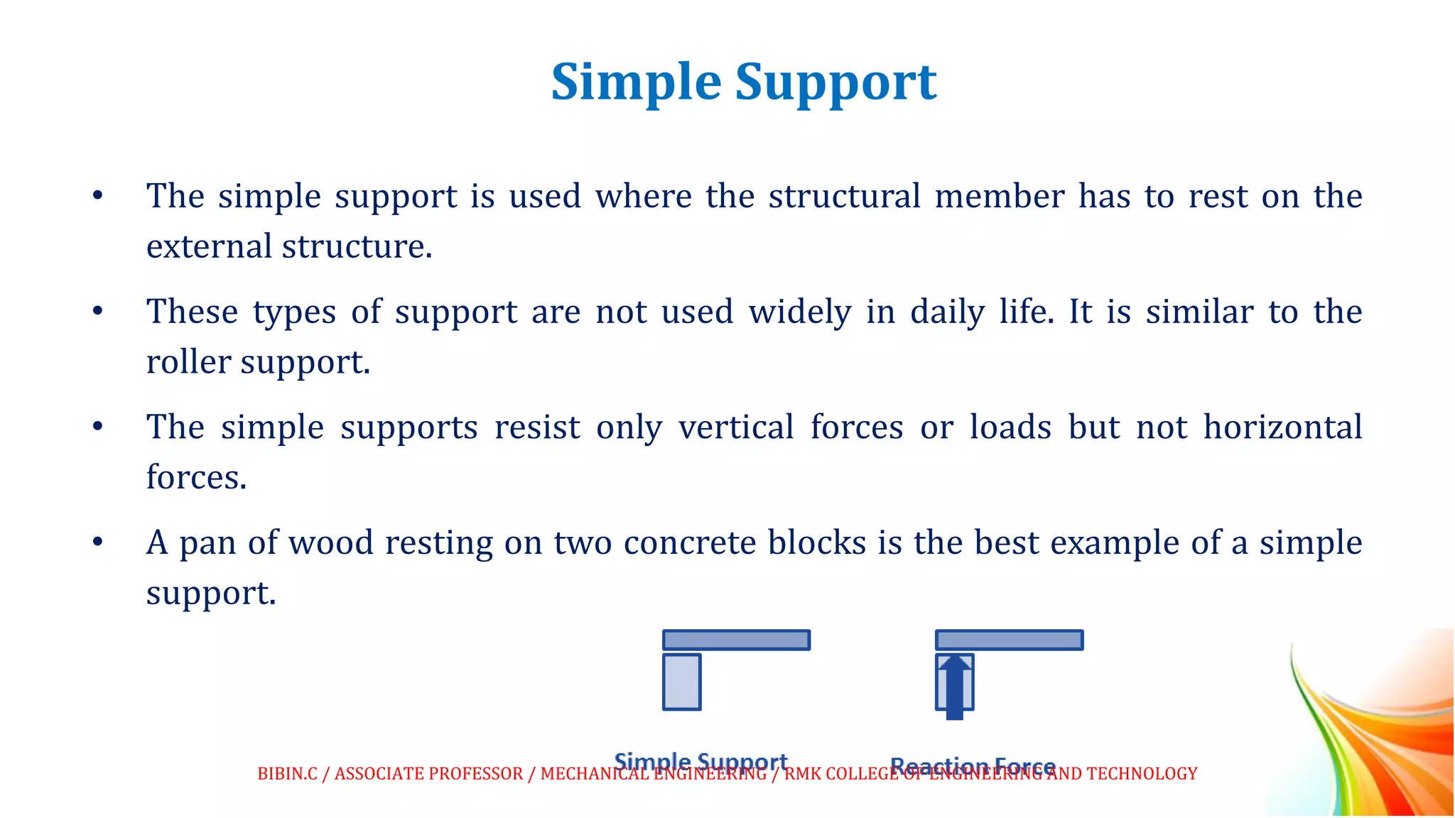
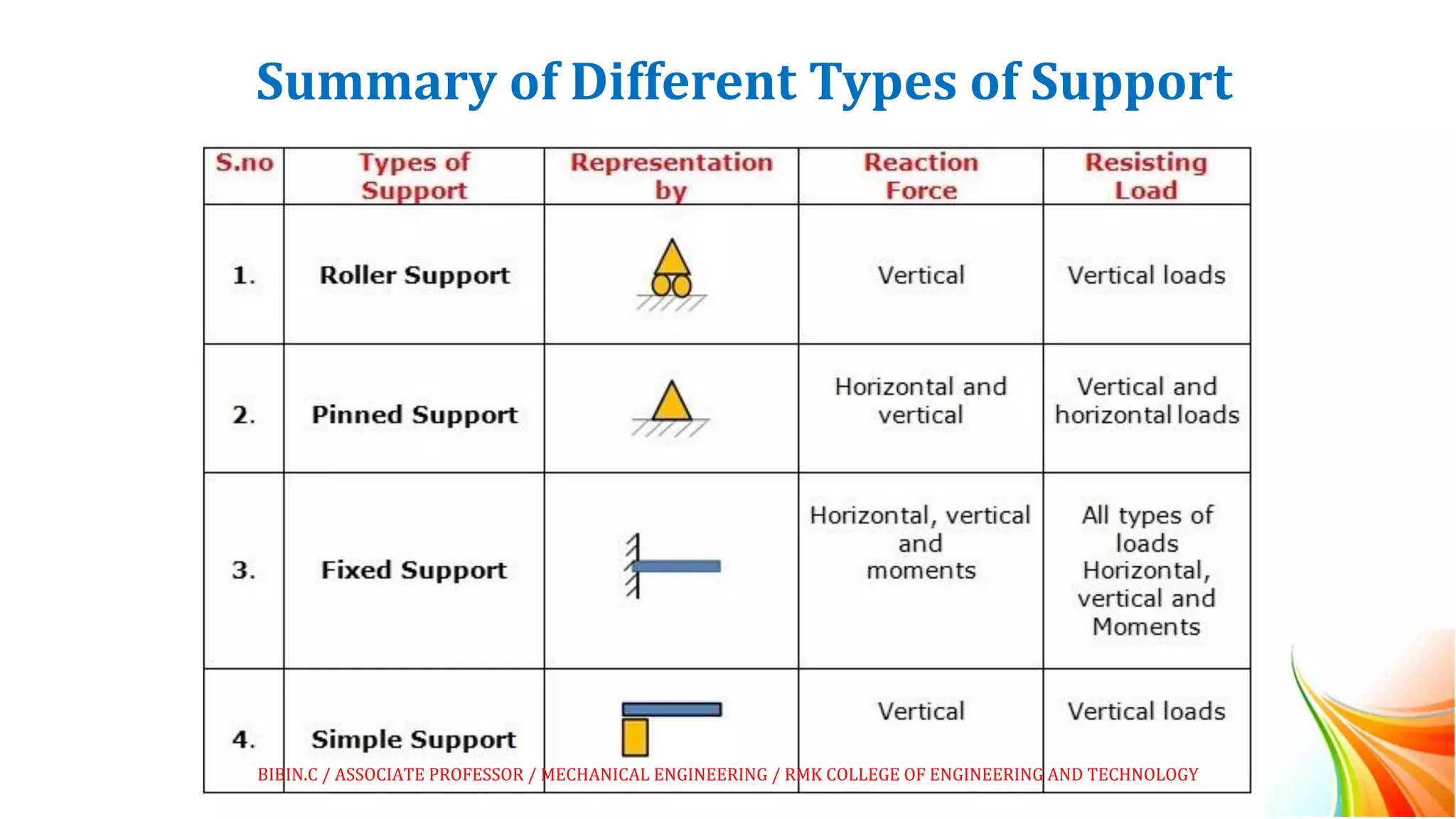
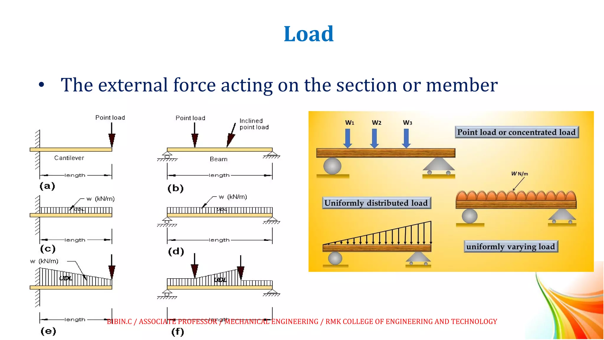
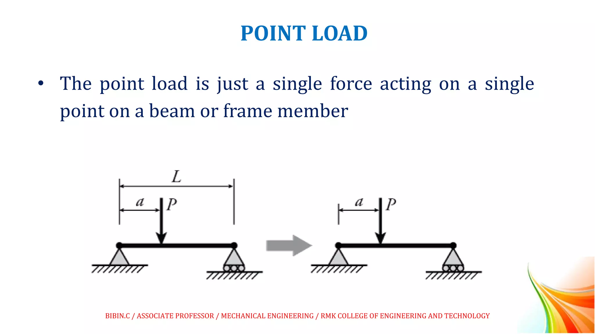
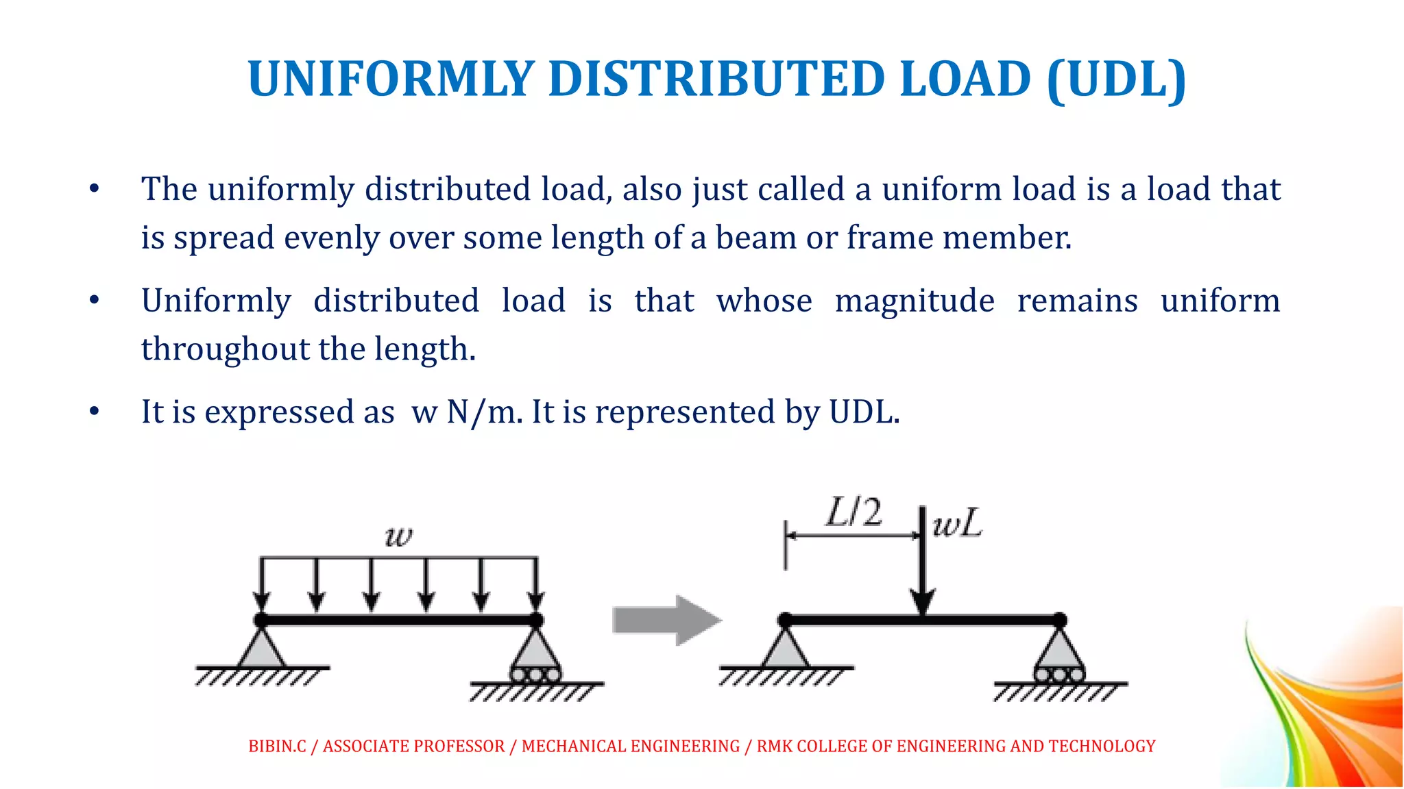
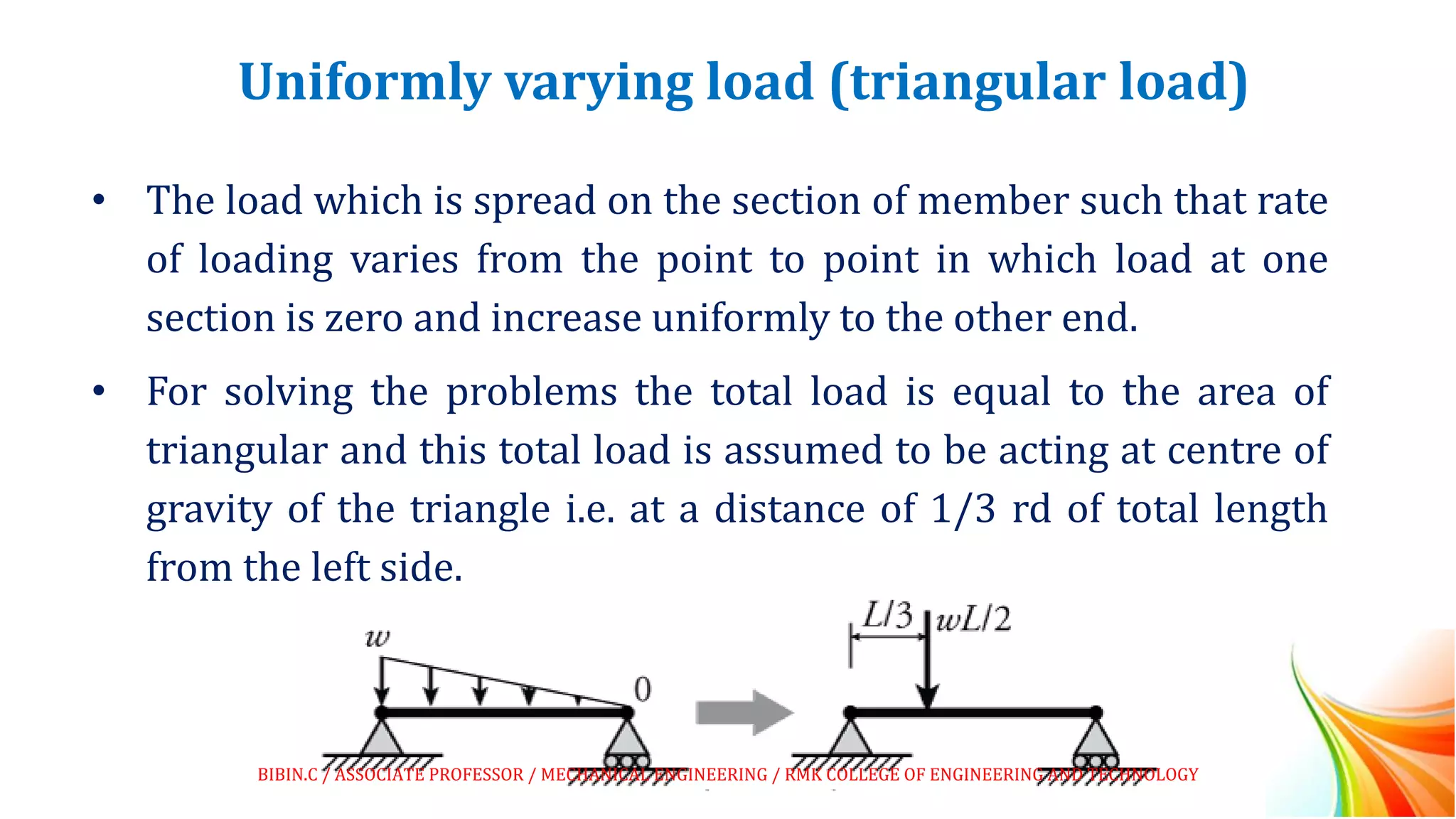
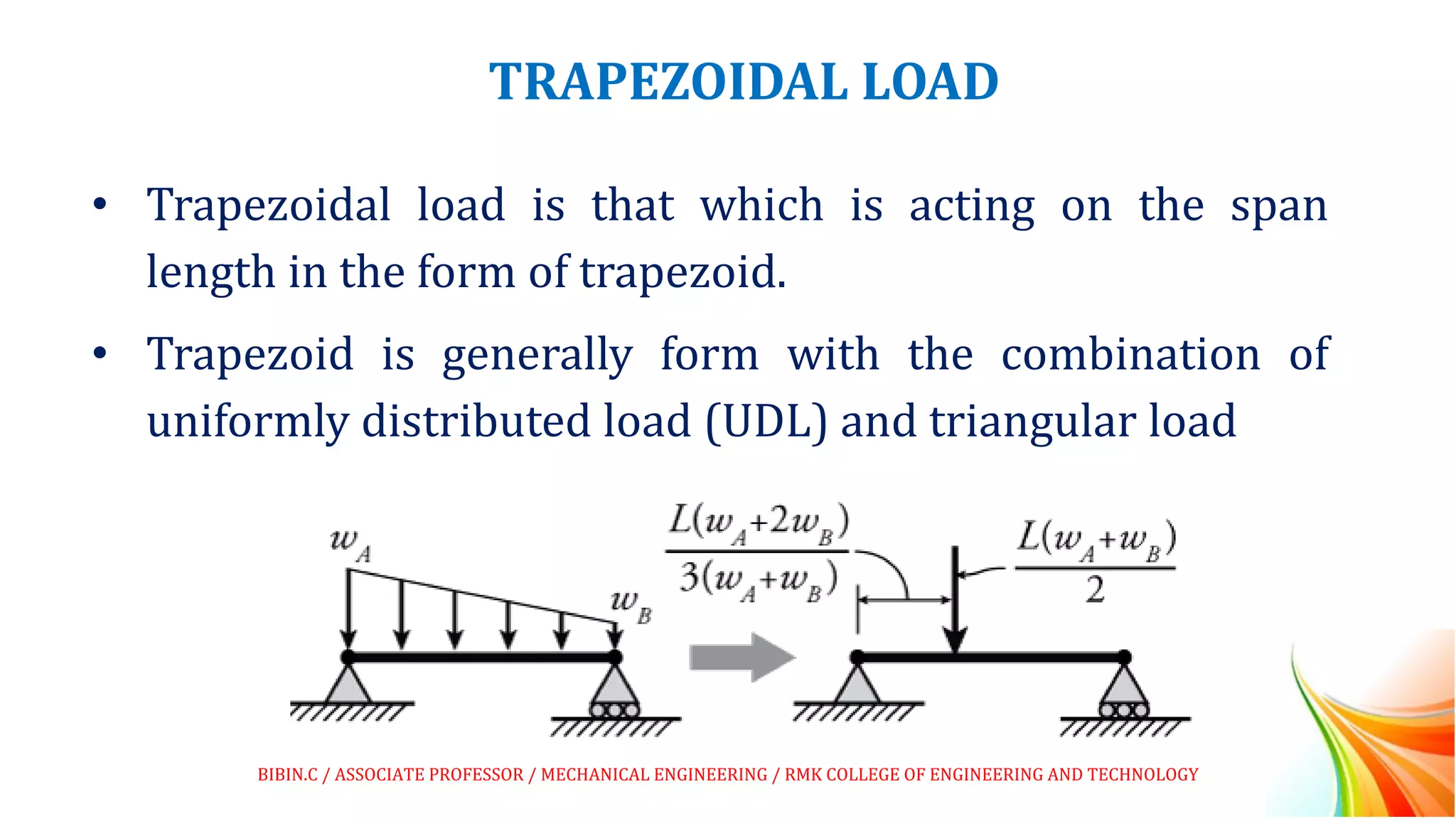
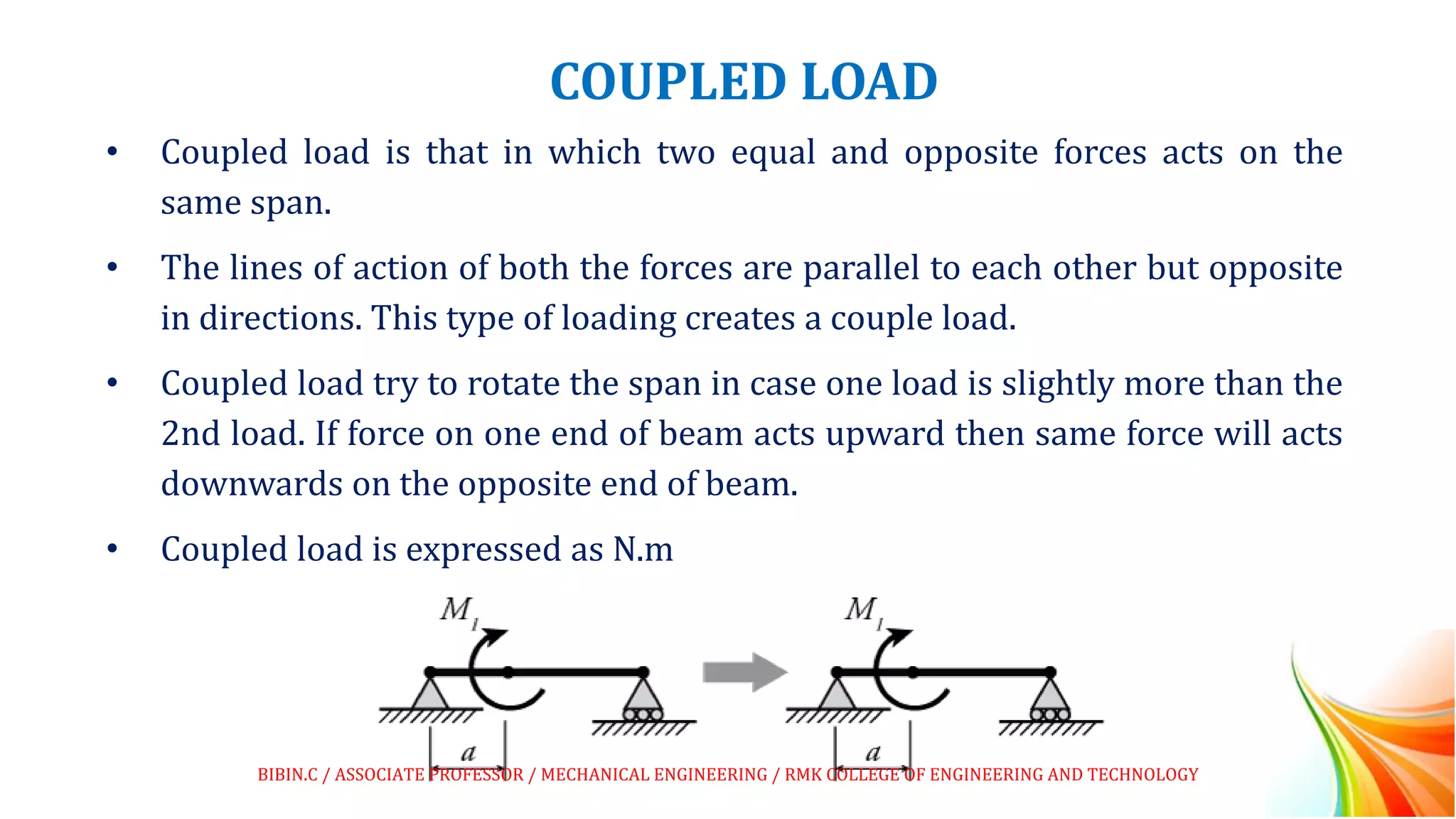
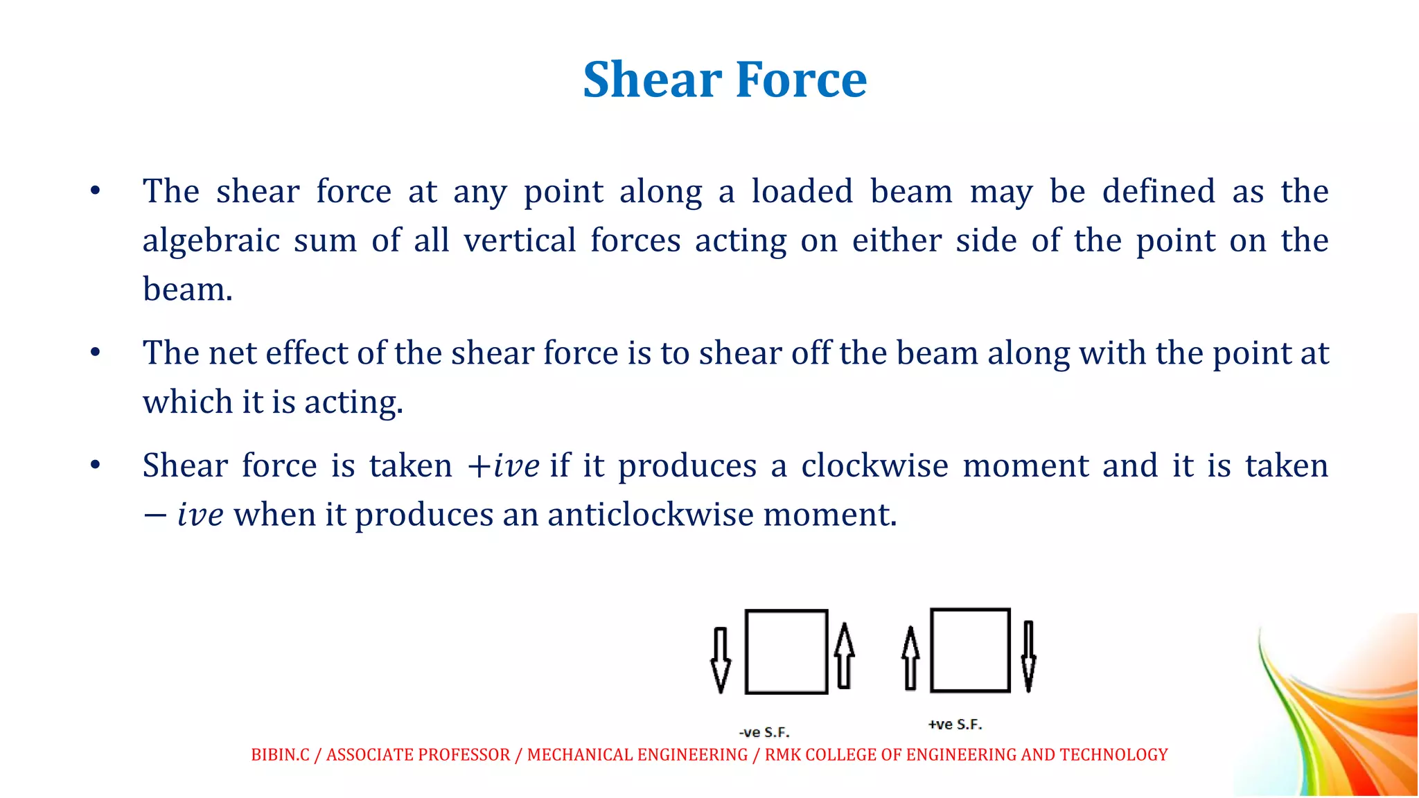
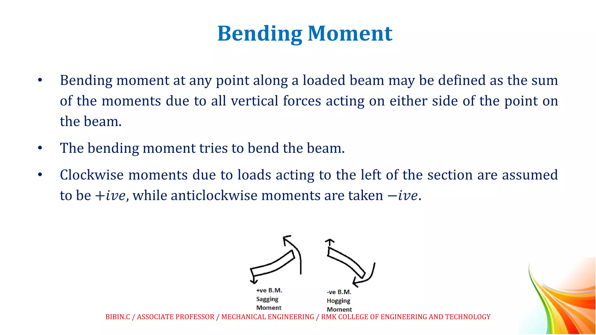


This document discusses beams and beam loading. It defines beams and describes different types of beams including cantilever, simply supported, overhanging, fixed, continuous, and propped cantilever beams. It also discusses beam supports, describing roller, pinned, fixed, and simple supports. Additionally, it covers loads on beams, identifying point loads, distributed loads, and coupled loads. Structures and beams can be either statically determinate or statically indeterminate, and the differences between these two types are explained.


