Download to read offline
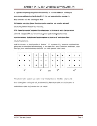

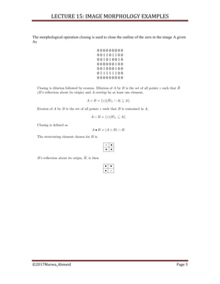
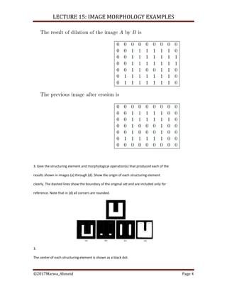
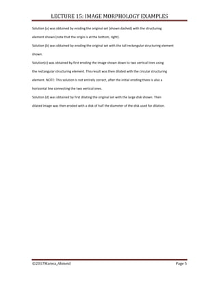
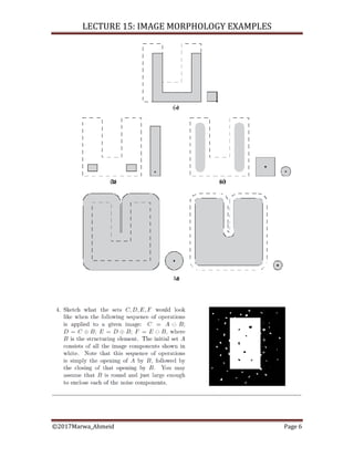


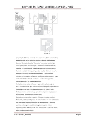


1. The document discusses morphological algorithms for converting an 8-connected binary boundary to an m-connected boundary. It describes using hit-or-miss transforms to detect patterns that cause multiple paths and eliminate the center pixel, requiring only one pass. The order of structuring elements matters as different orders can produce different m-paths. 2. It describes using the morphological closing operation to close the outline of a zero in an image. 3. It asks to identify the structuring element and operation used to produce images showing erosion, dilation, and other operations, noting centers and orientations of structuring elements.


![Lec07-CH9-MORPHOL [Recovered].ppt](https://cdn.slidesharecdn.com/ss_thumbnails/lec07-ch9-morpholrecovered-220706082019-67054ec6-thumbnail.jpg?width=640&height=640&fit=bounds)


