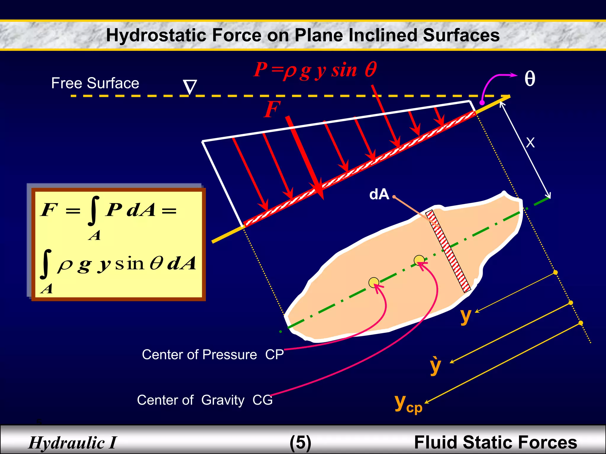
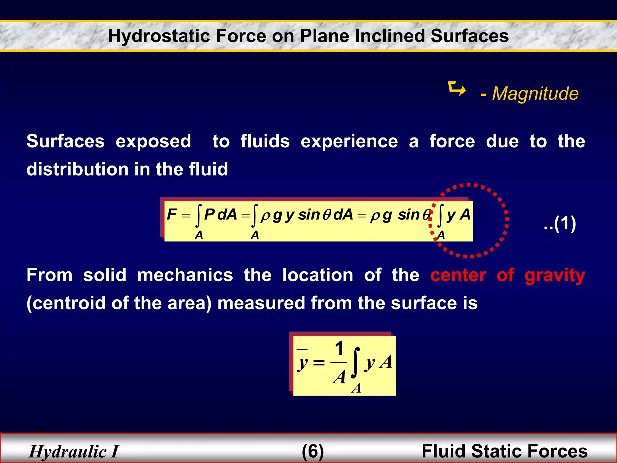
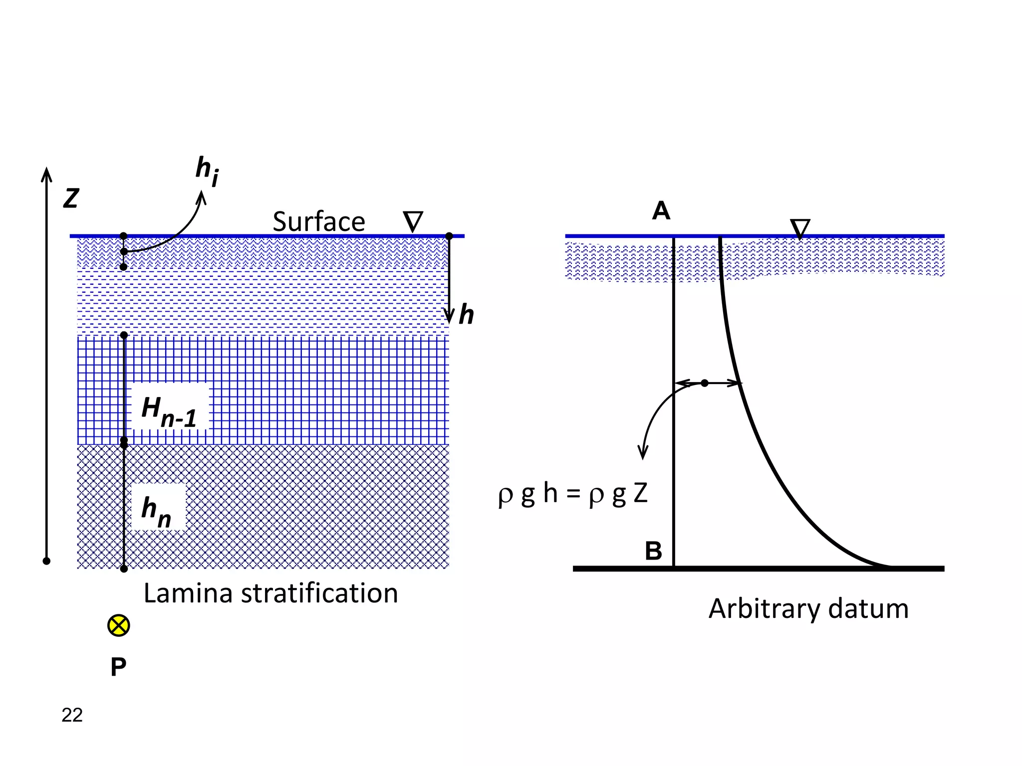
1. Fluid static forces act on surfaces exposed to fluids due to pressure distributions in the fluid. The magnitude and direction of these forces depend on factors like the surface geometry, depth of submergence, and fluid properties.
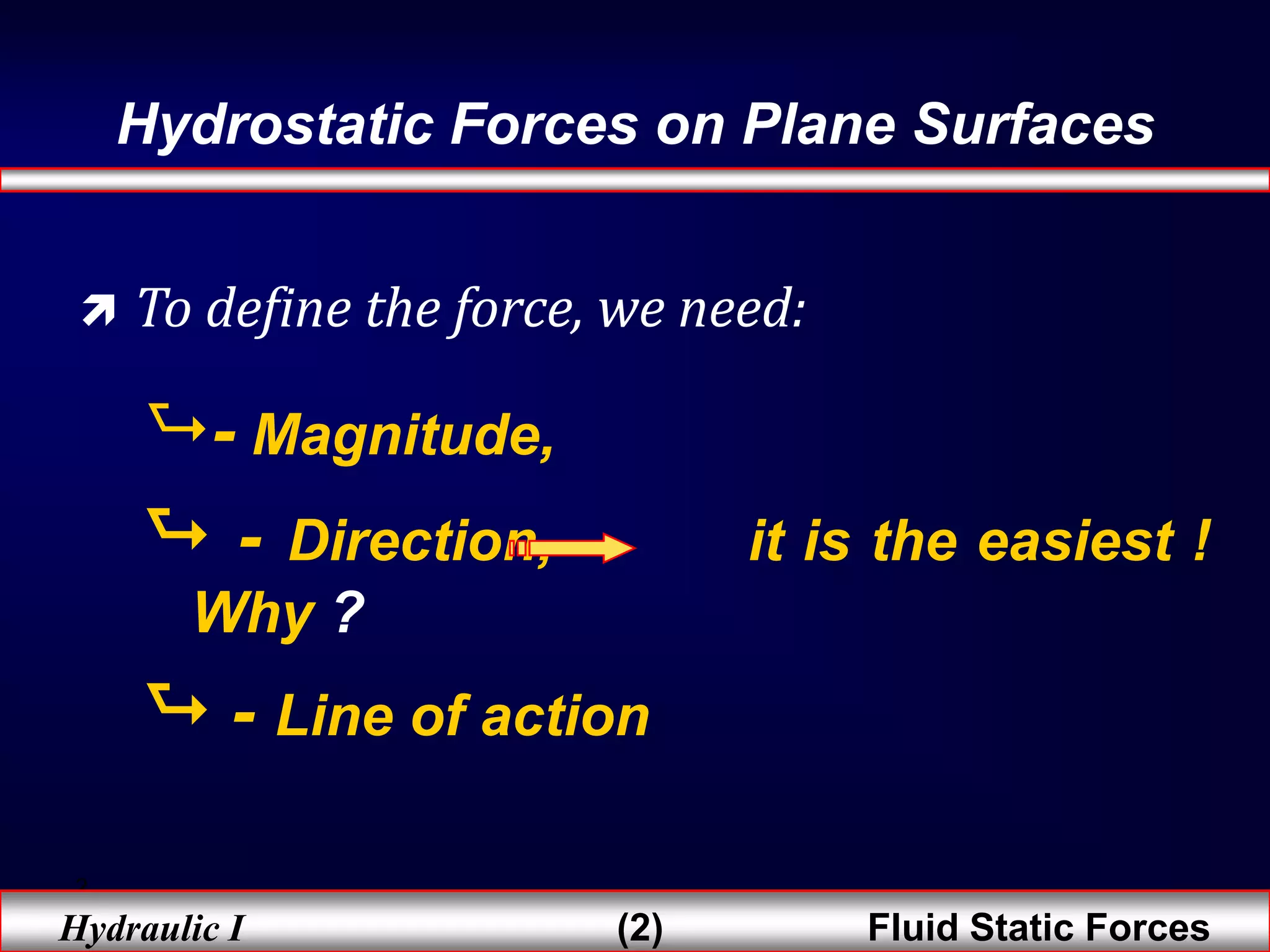
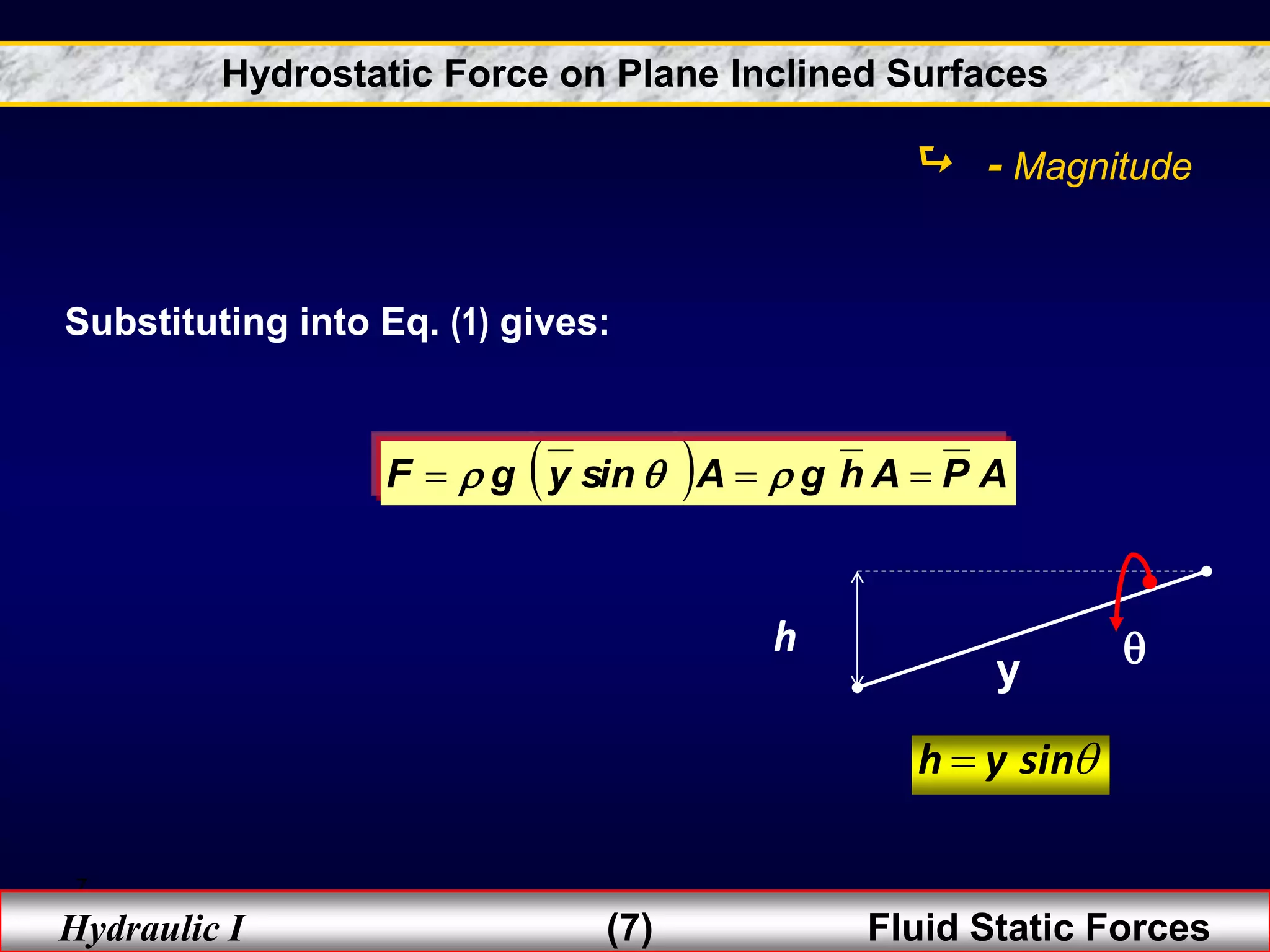
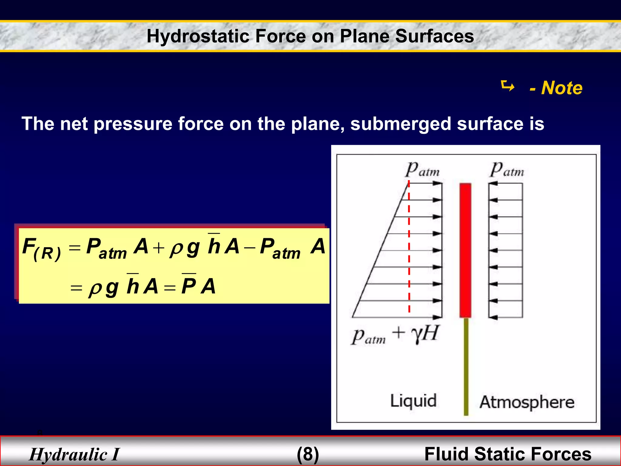
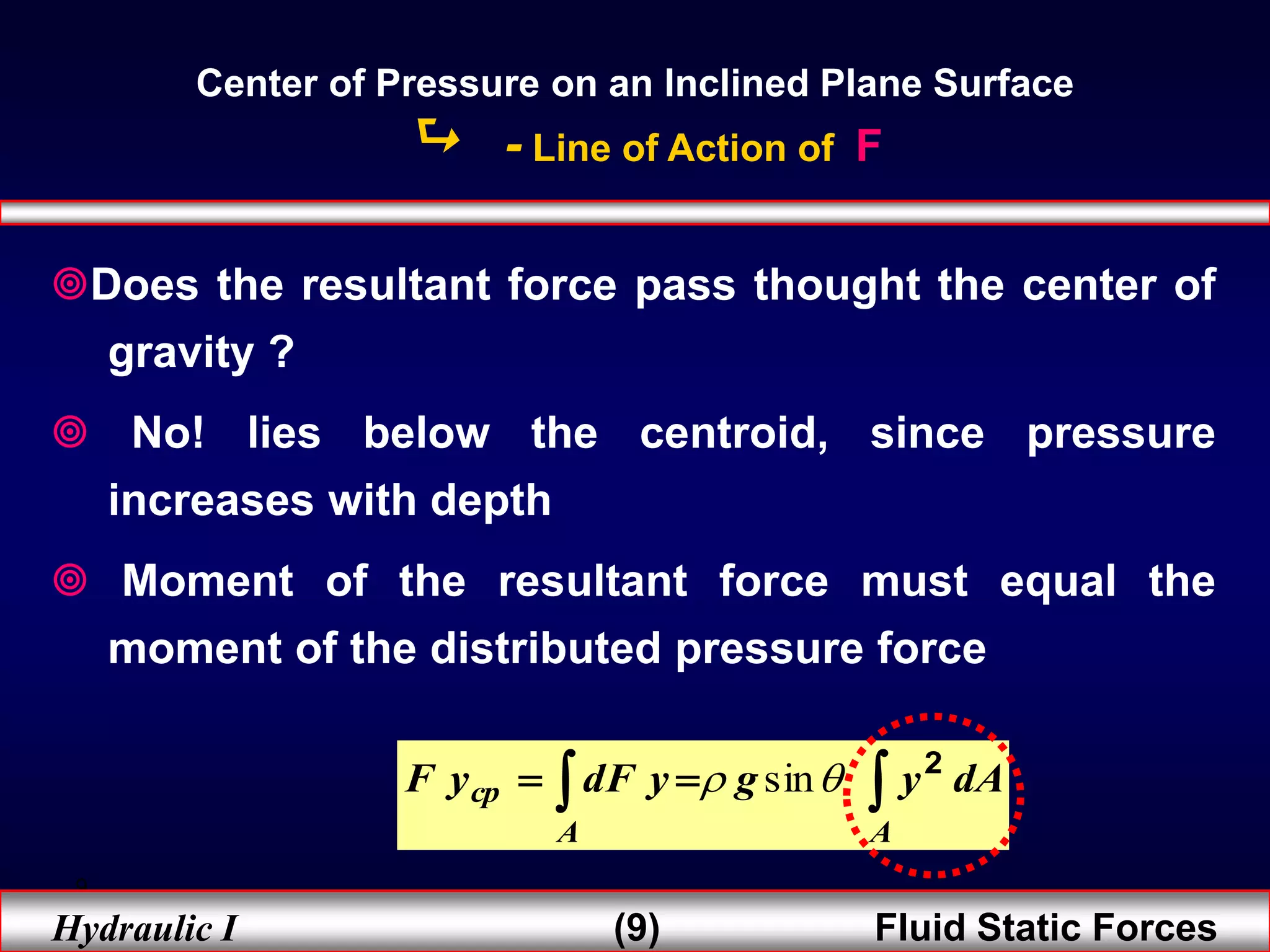
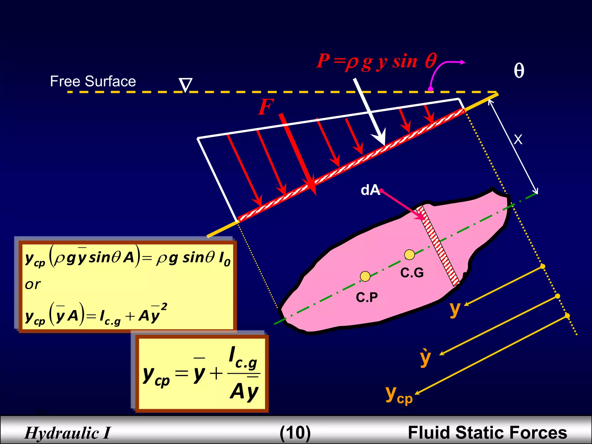
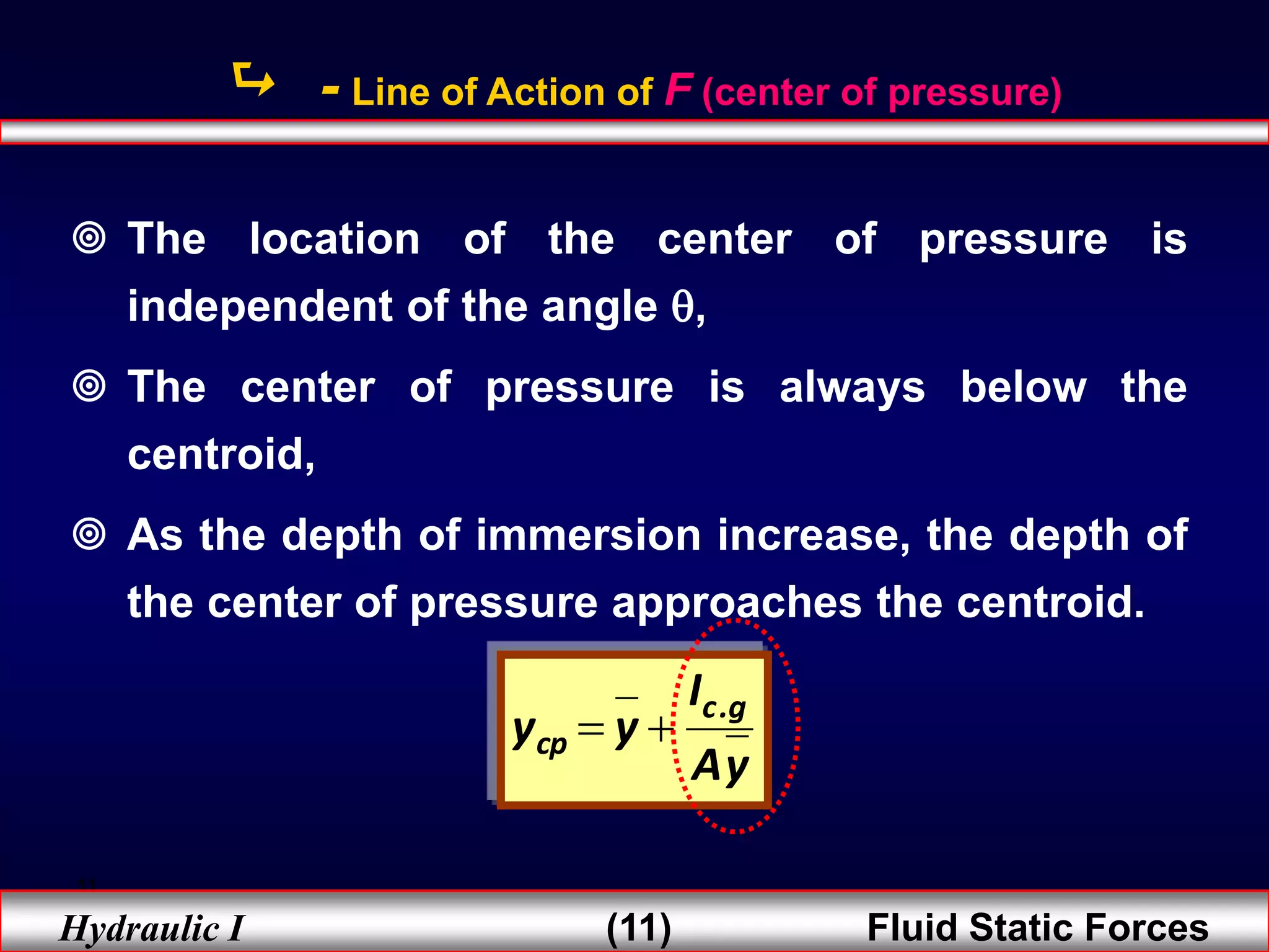
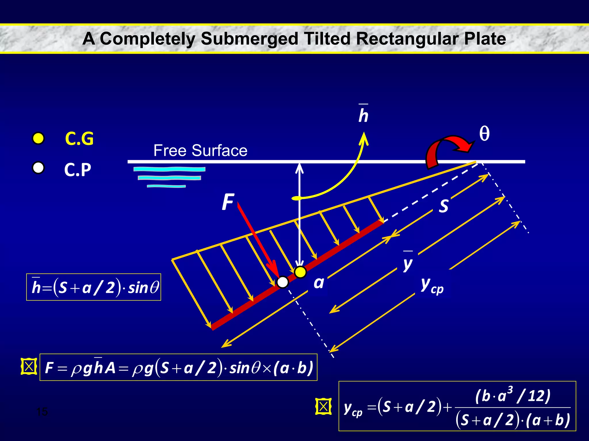
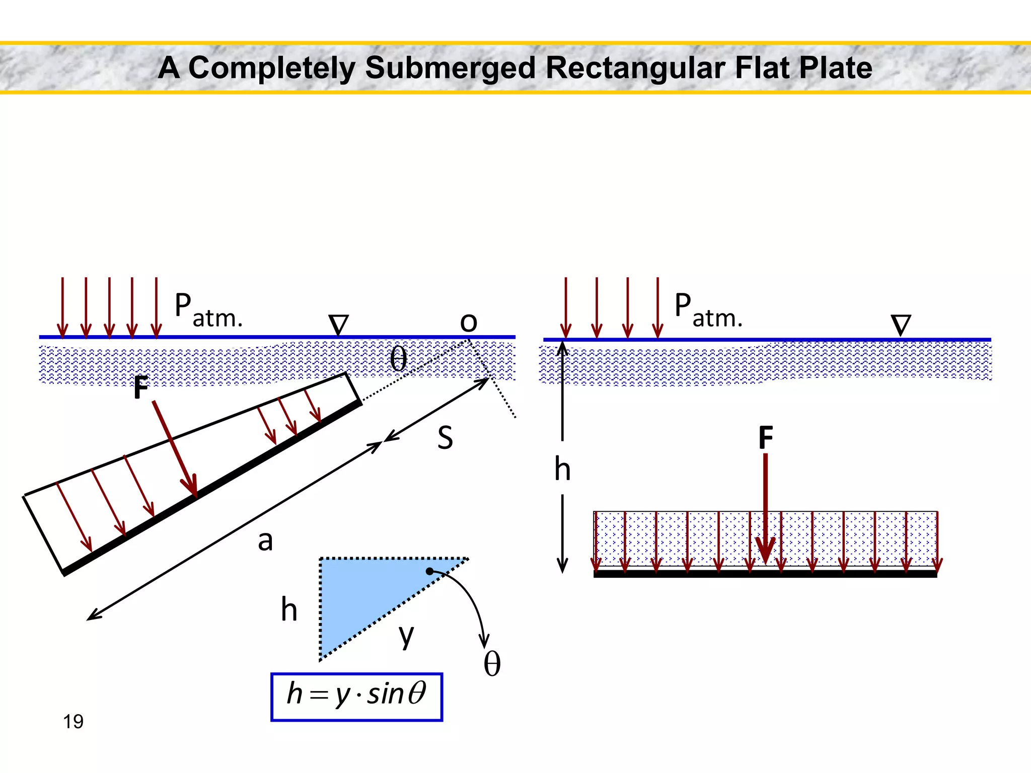
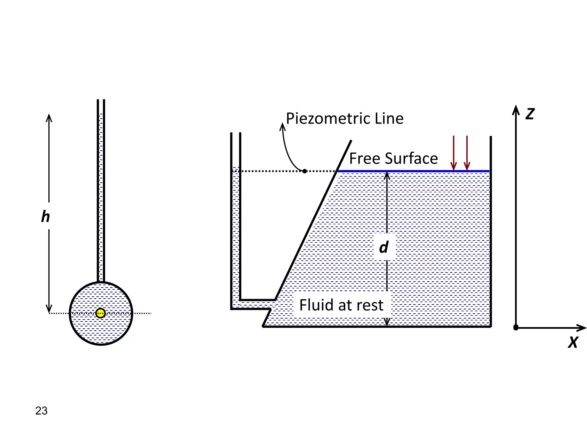
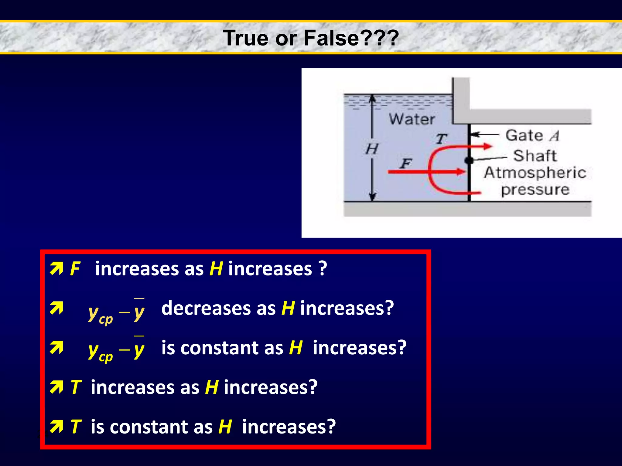
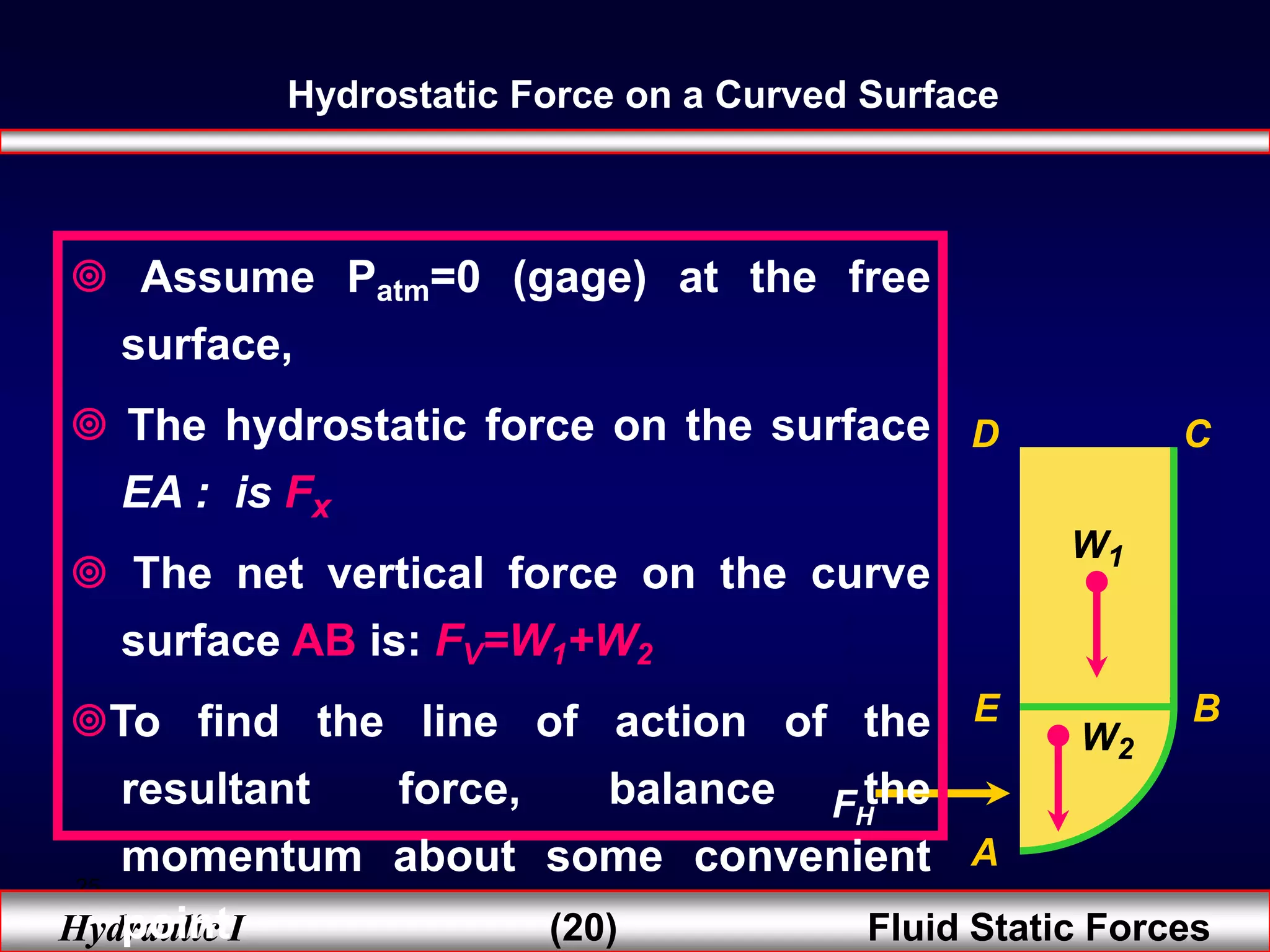
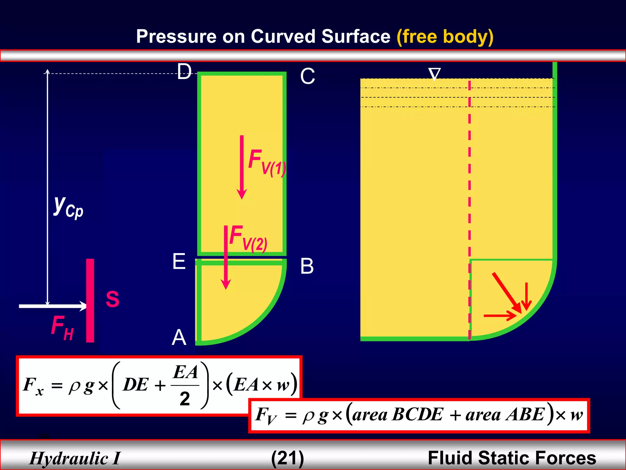
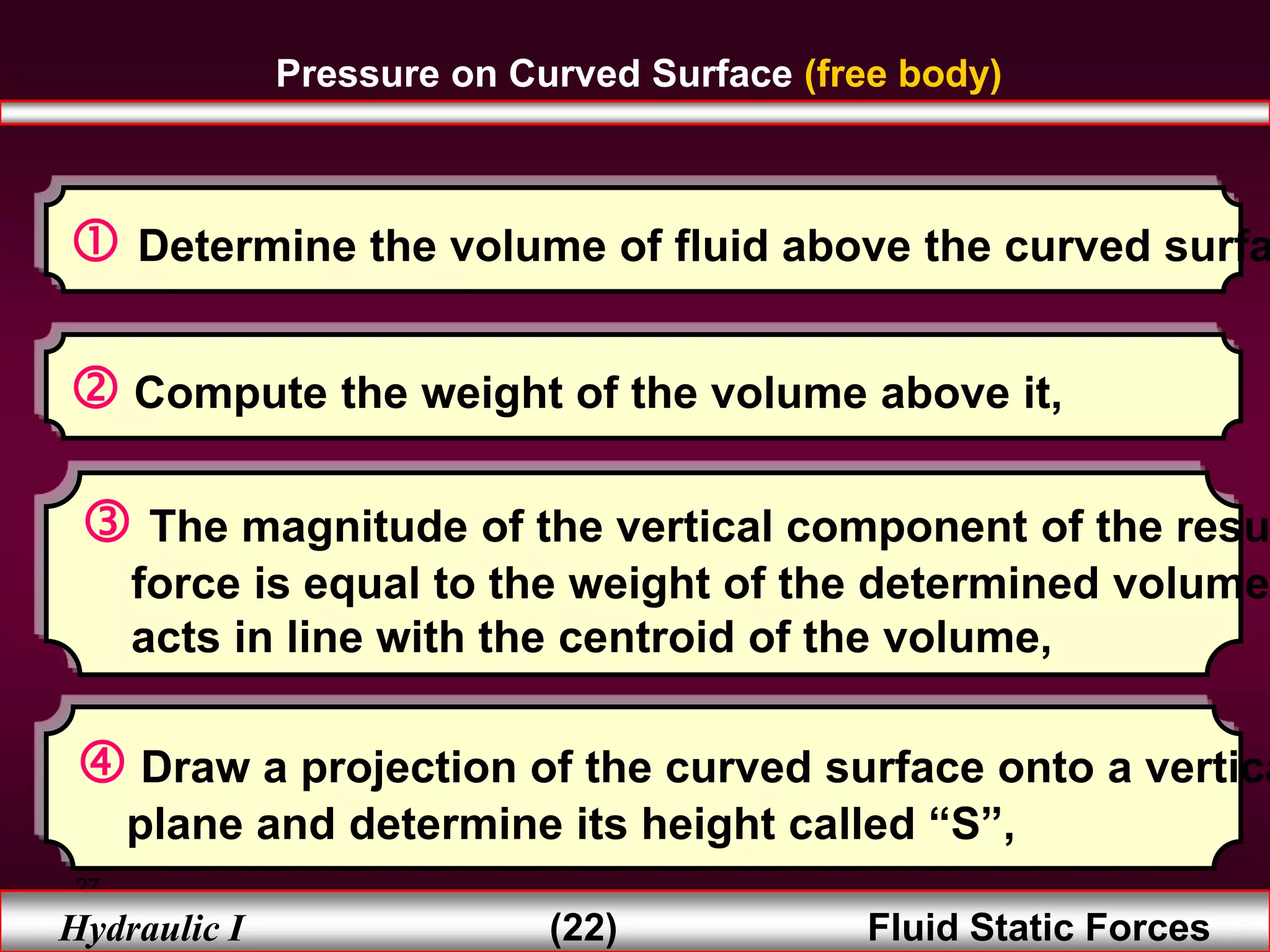
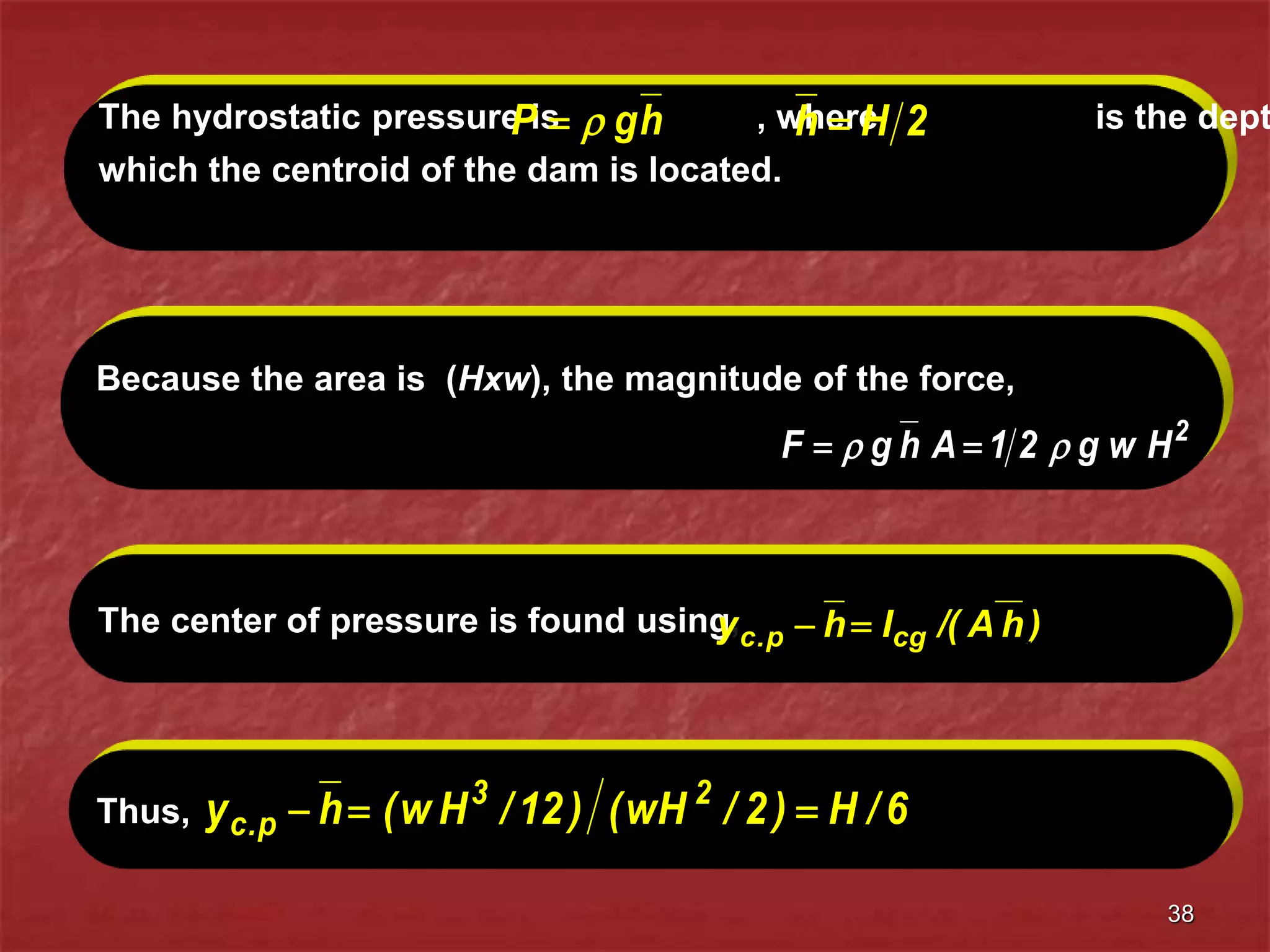
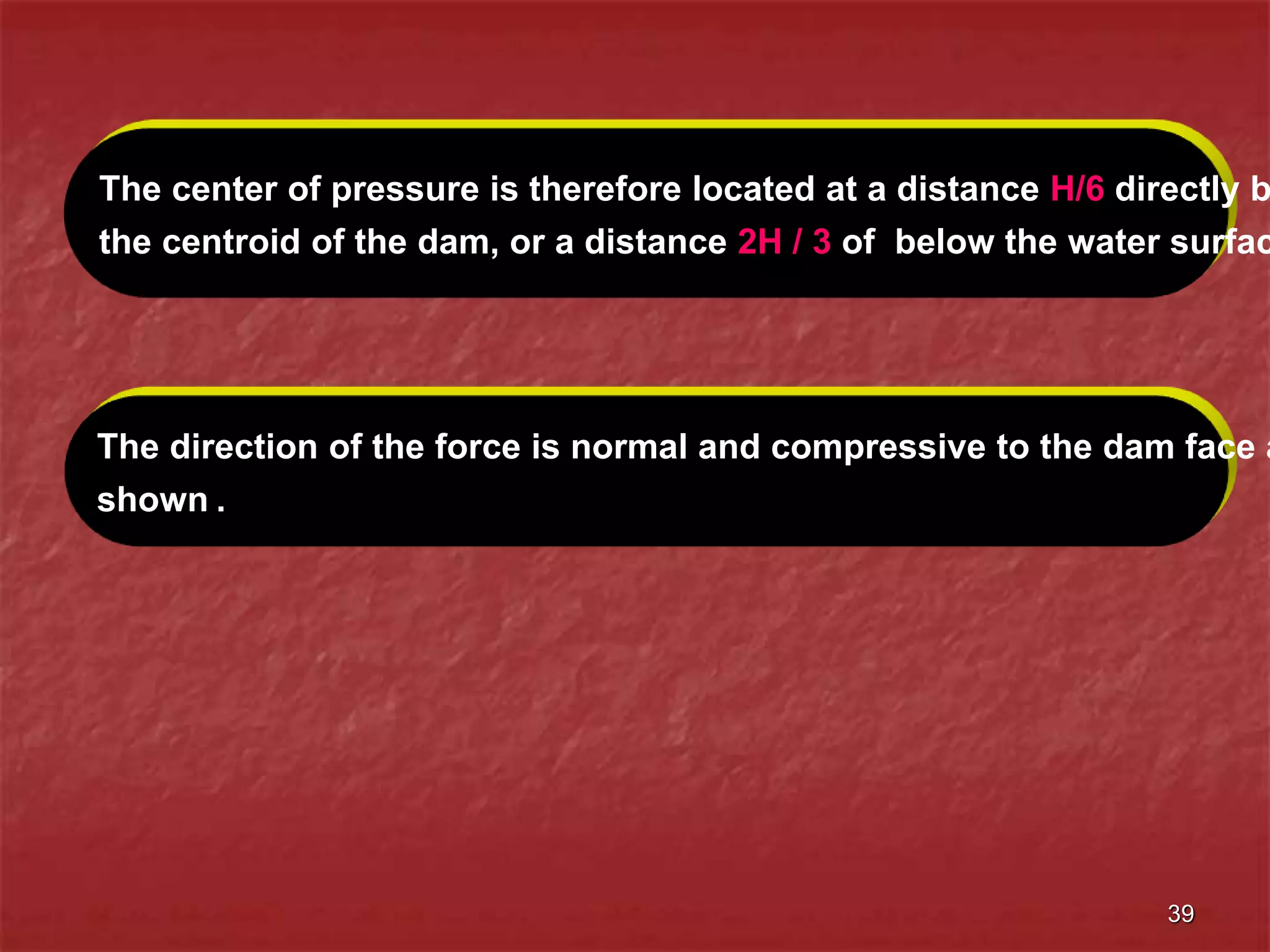
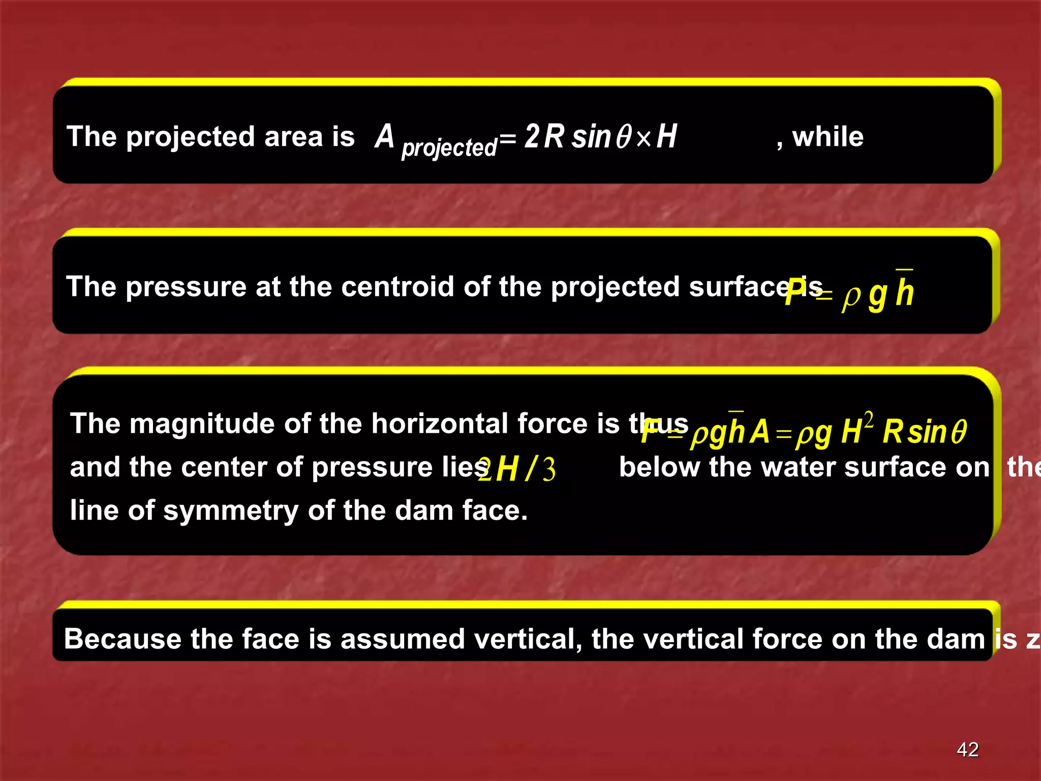
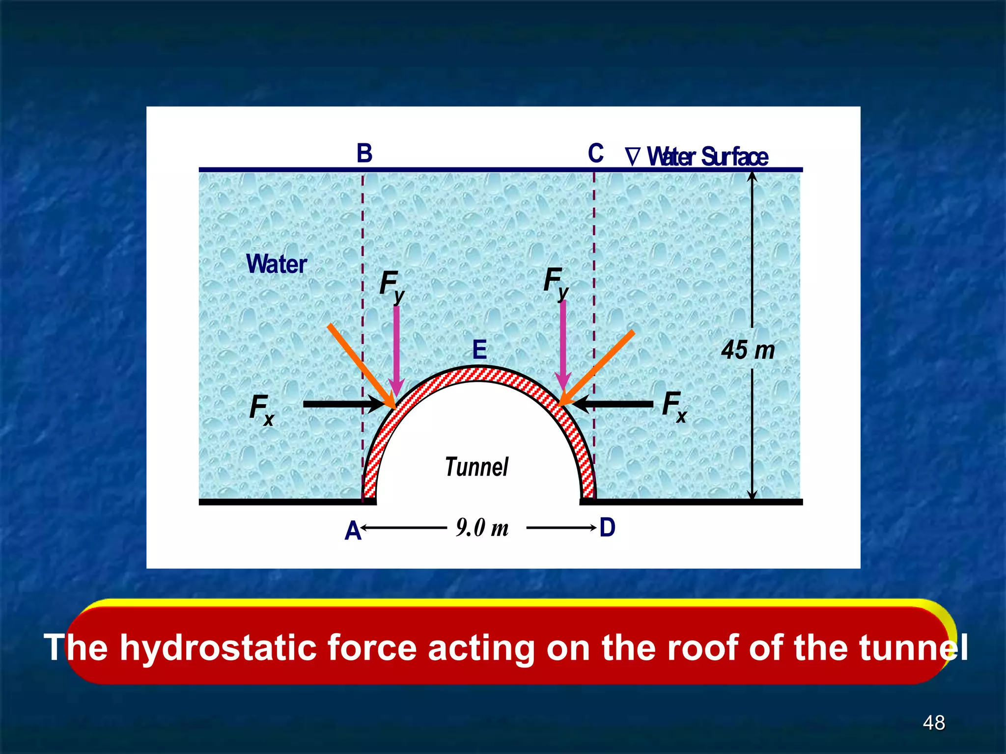
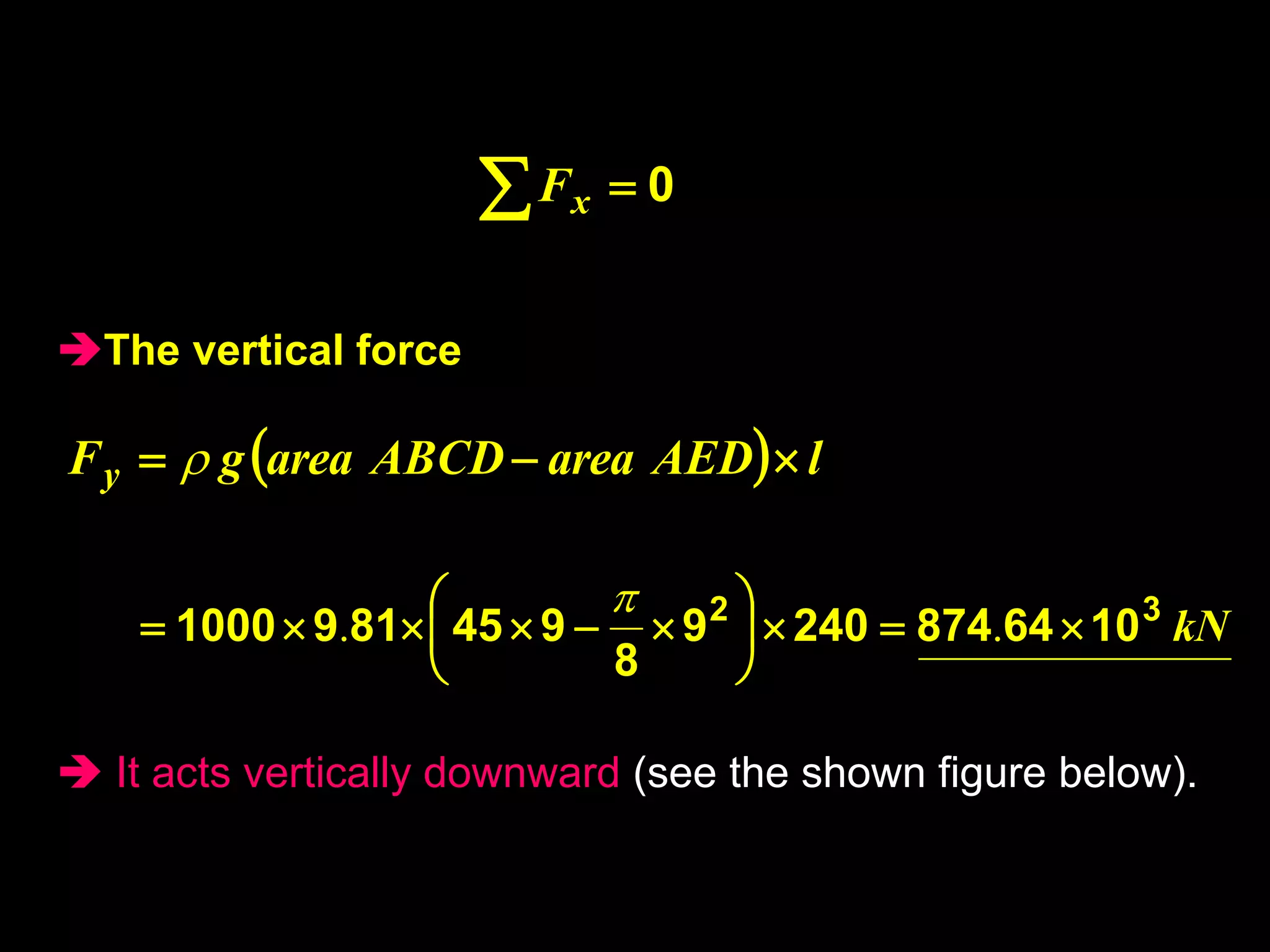
2. Hydrostatic forces can be resolved into vertical and horizontal components, with the vertical force equal to the weight of the displaced fluid. The location of the center of pressure determines the line of action of the resultant force.
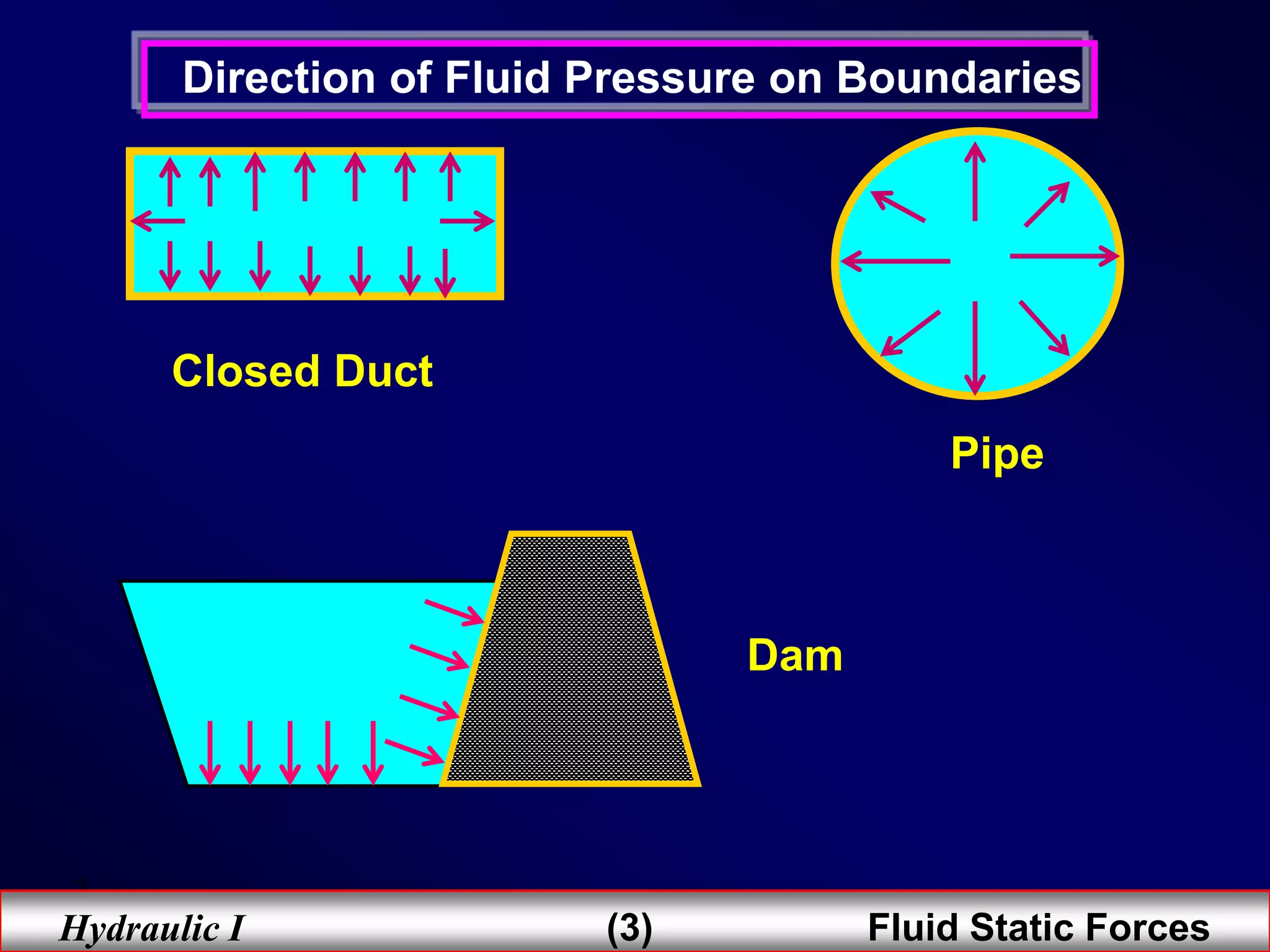
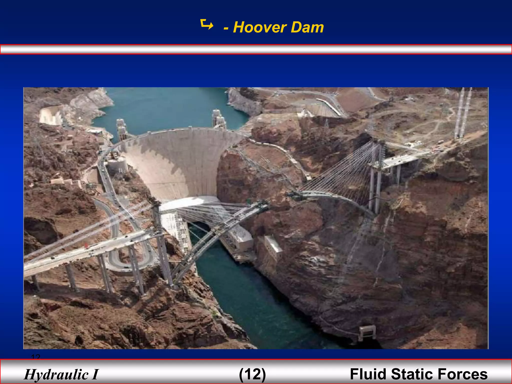
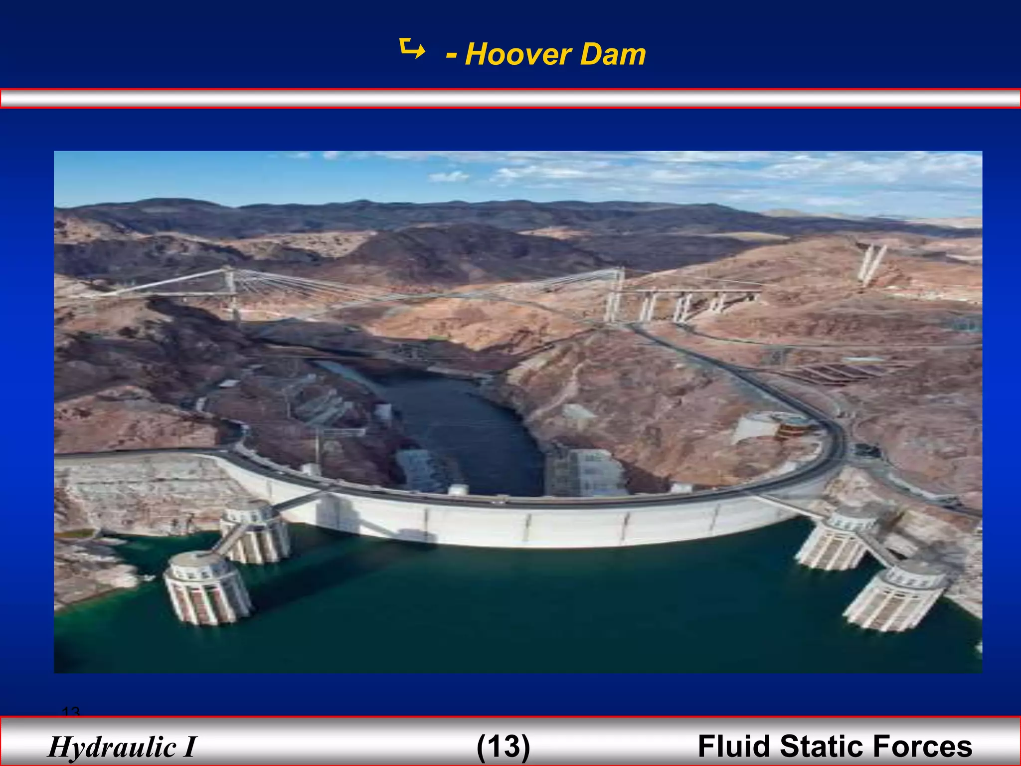
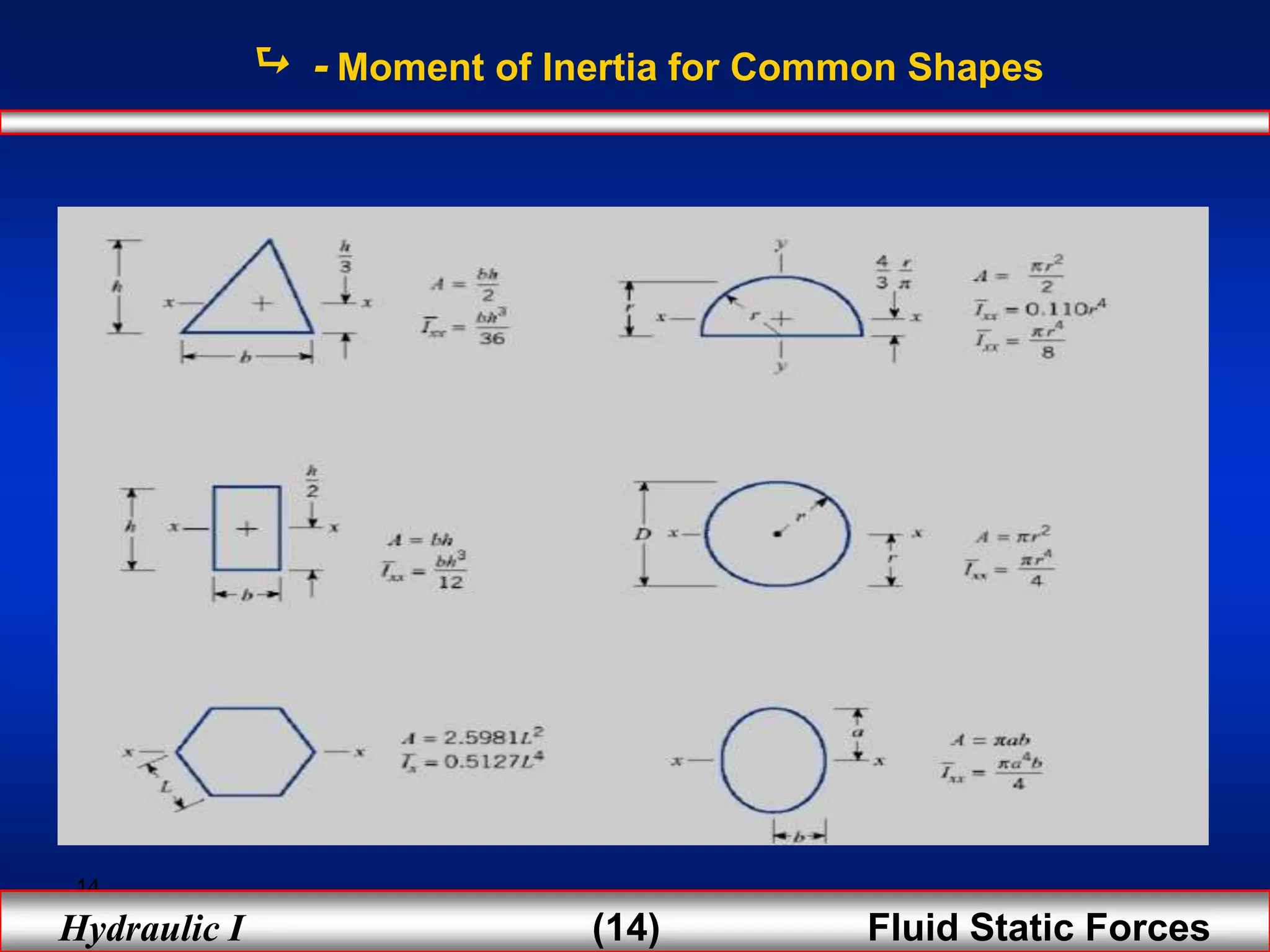
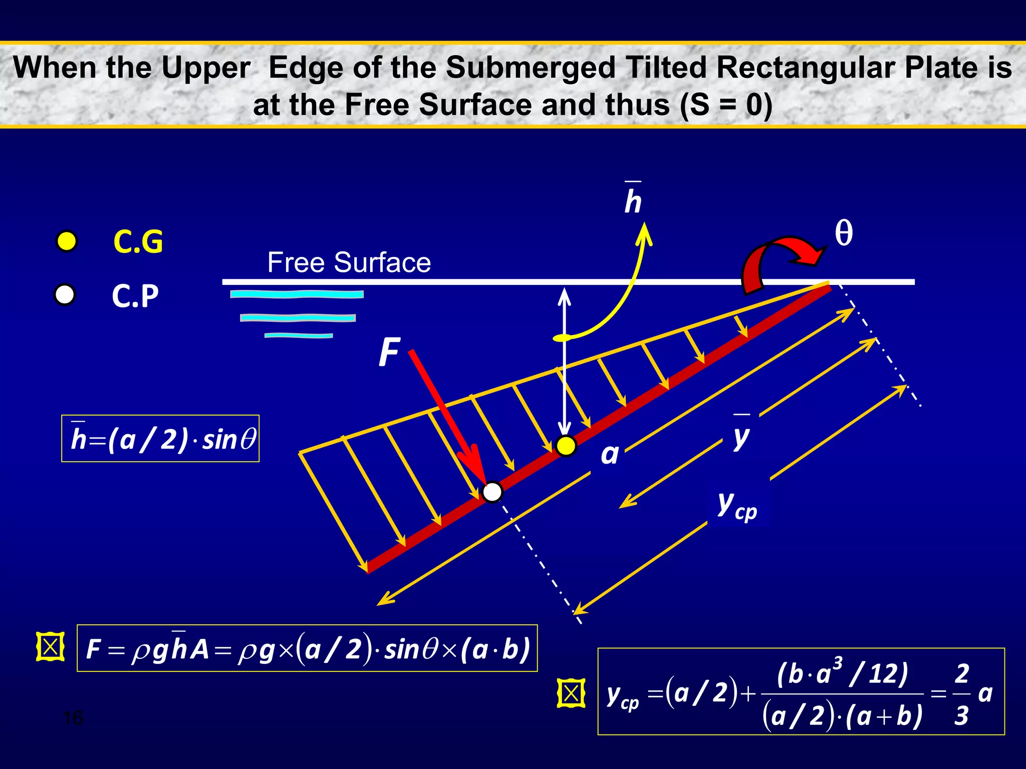
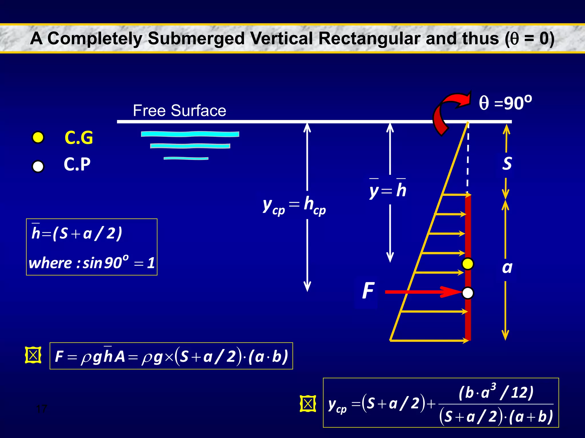
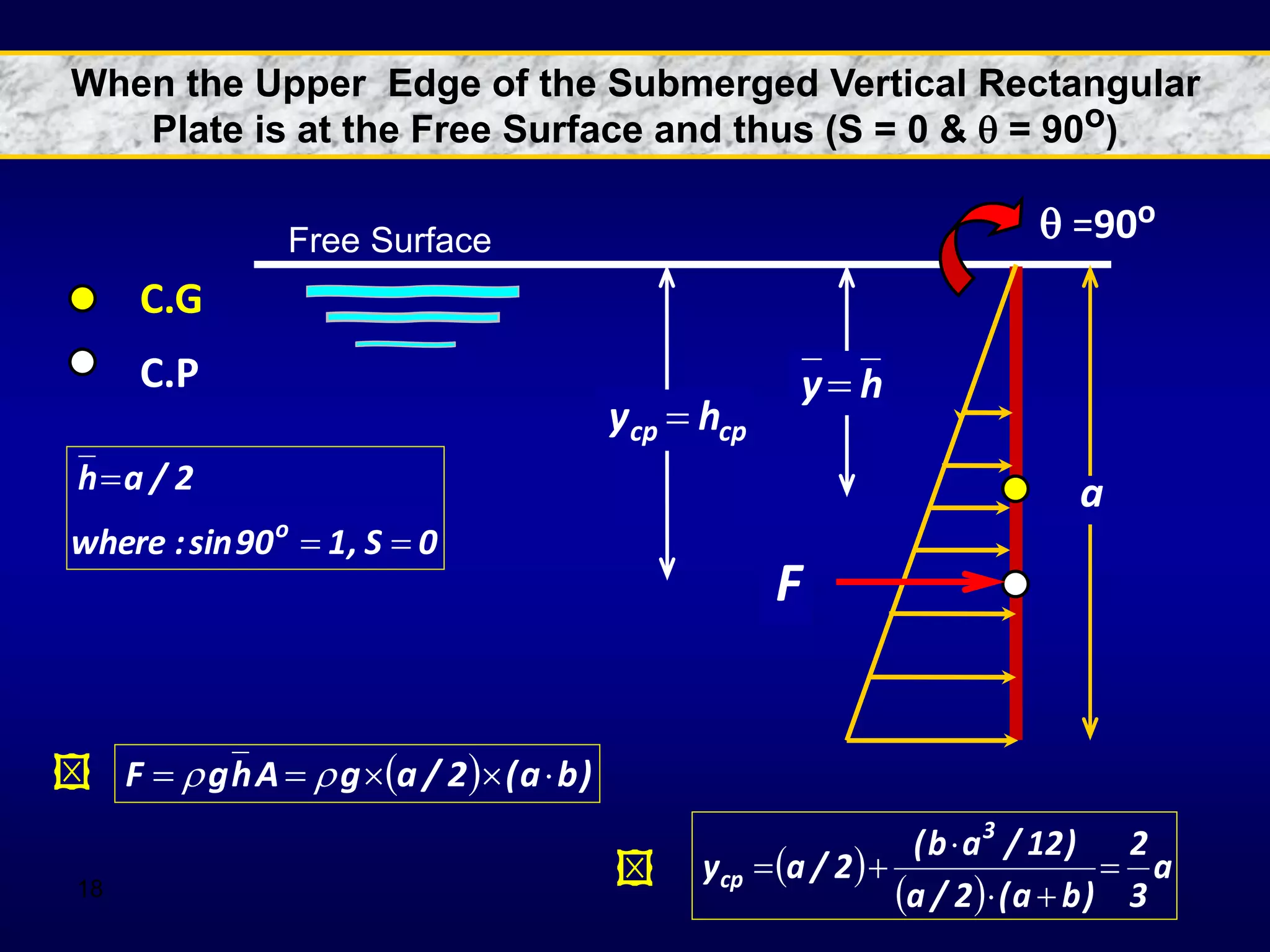
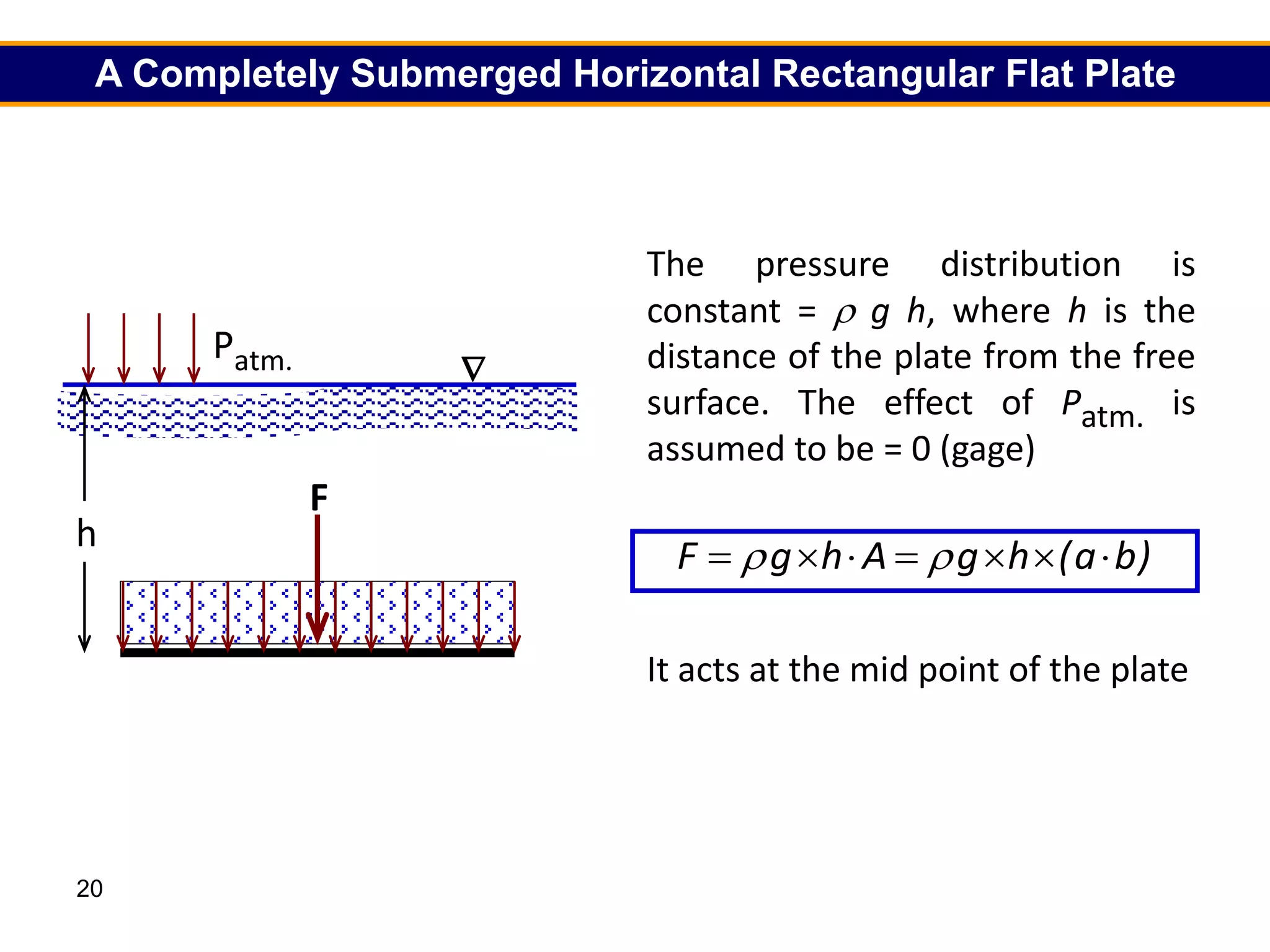
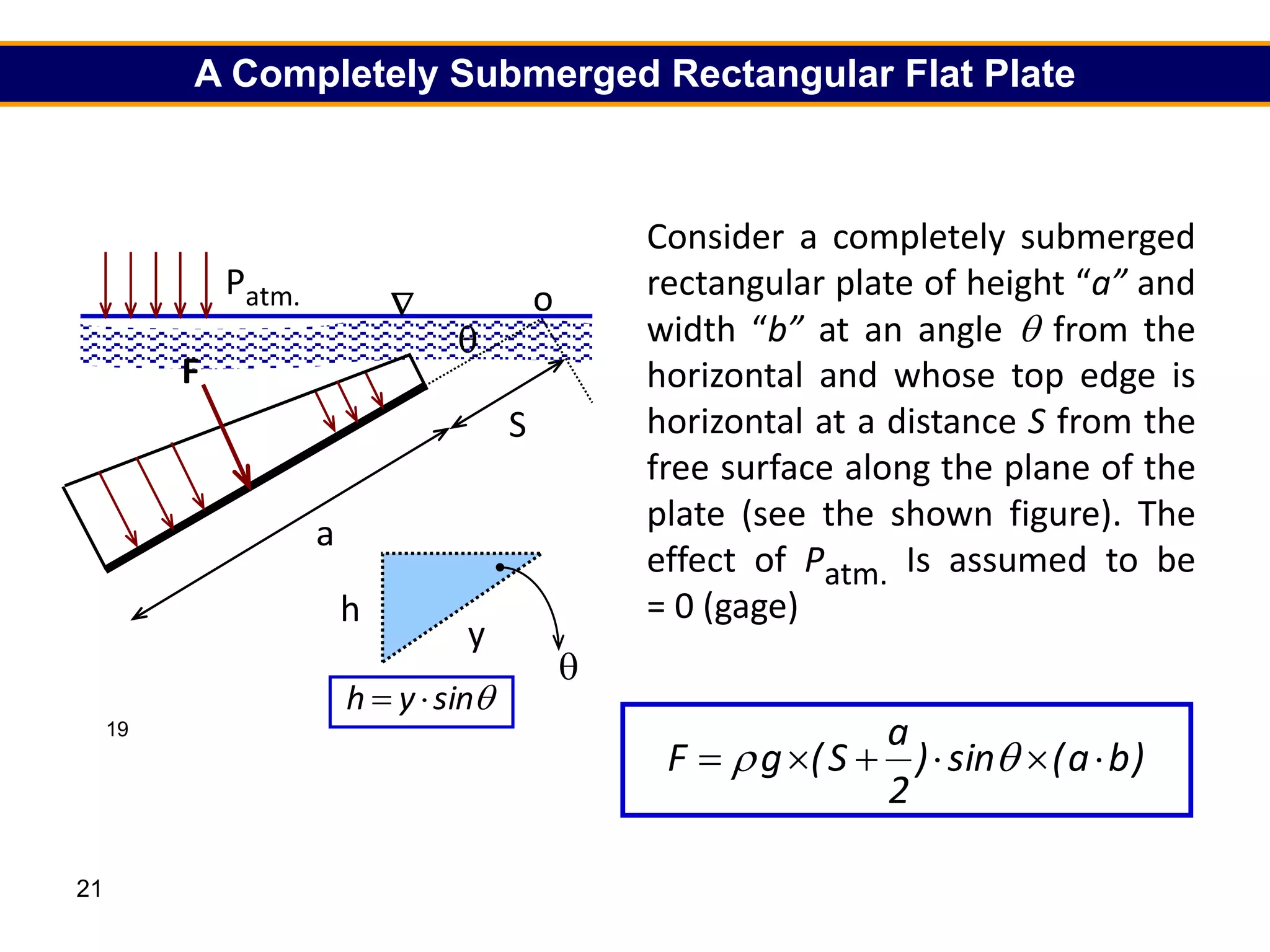
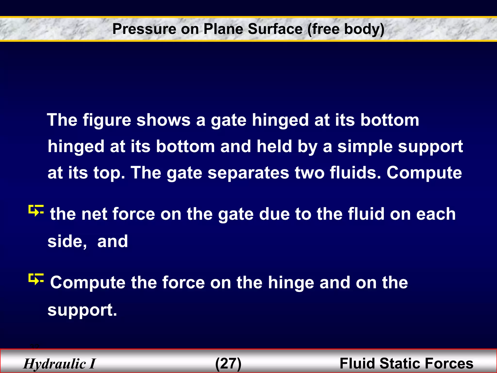
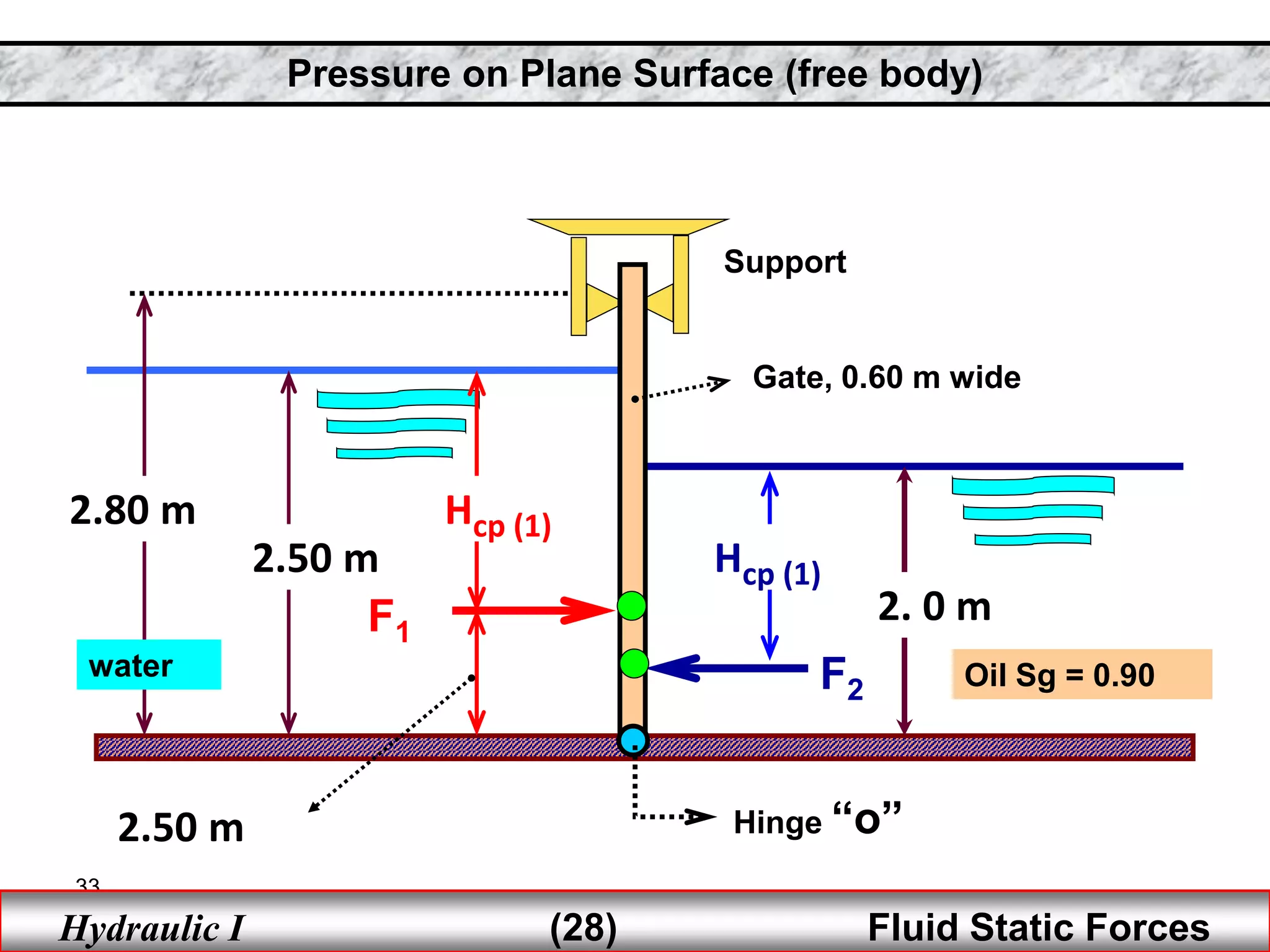
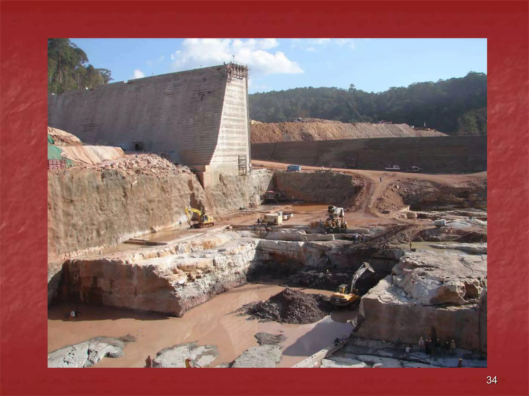
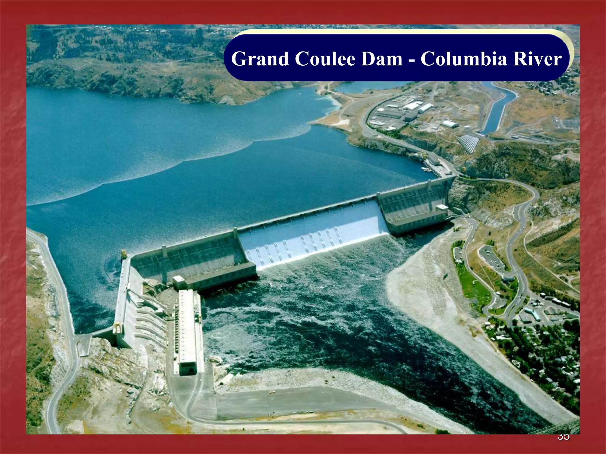
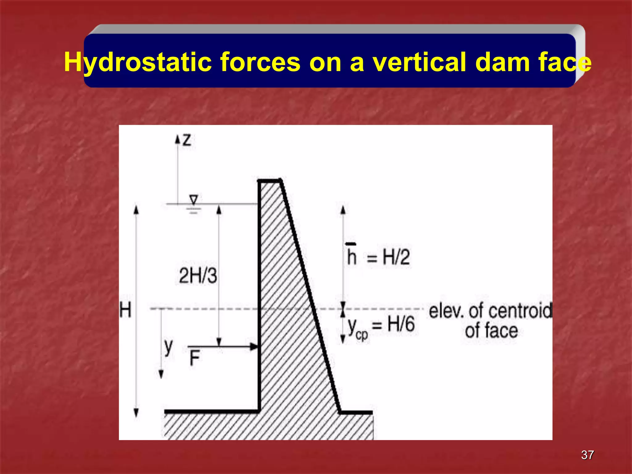
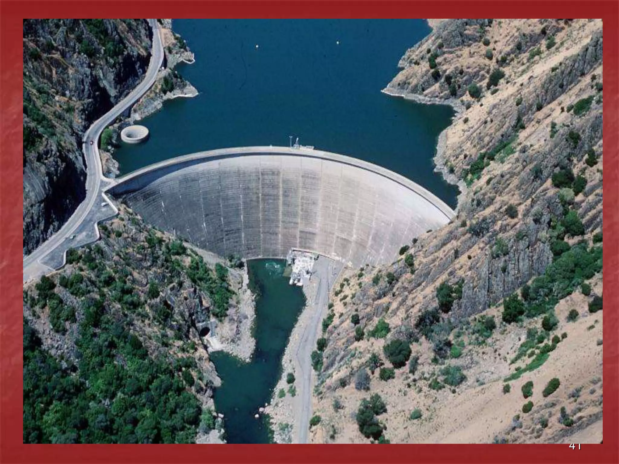
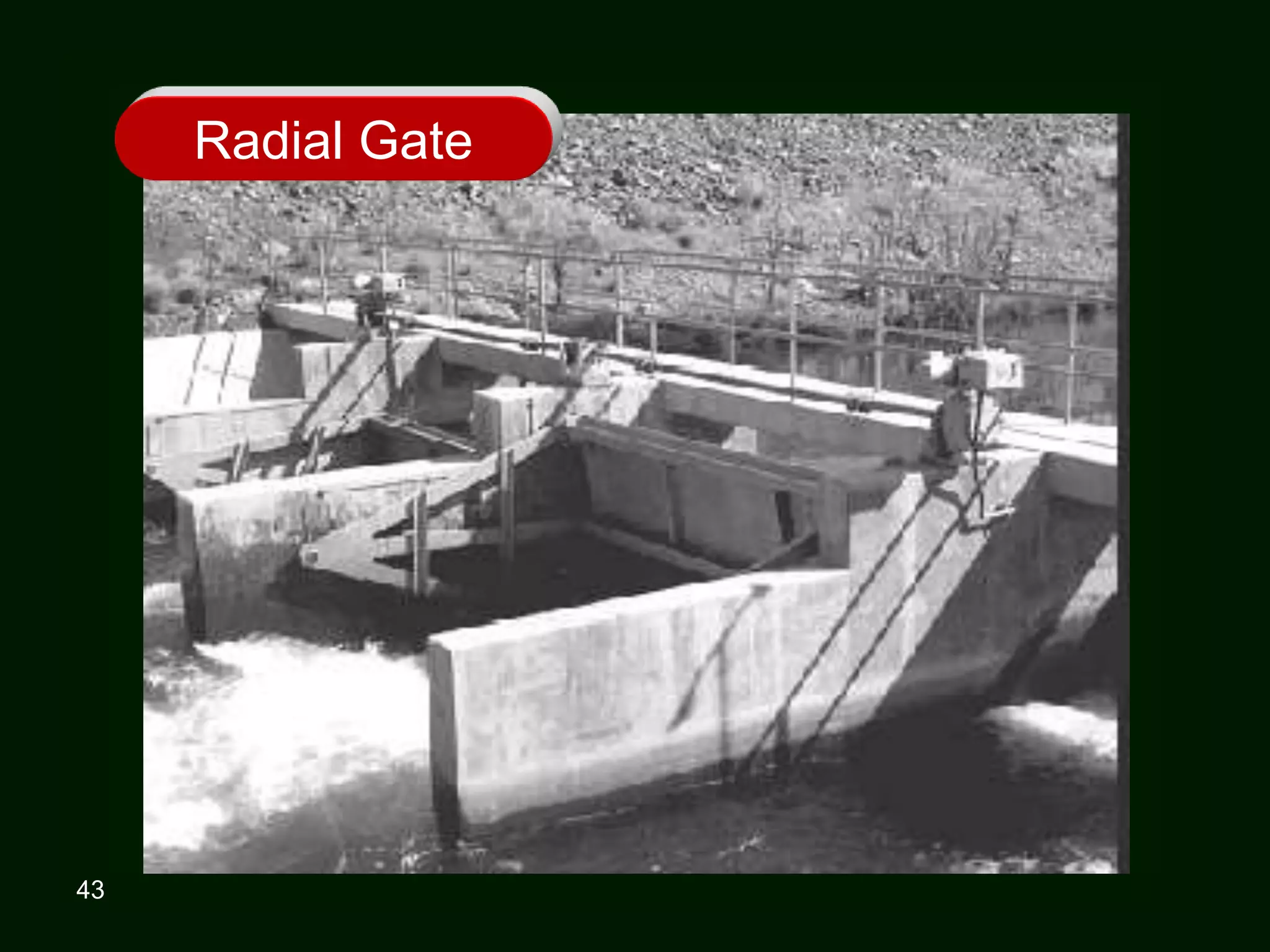
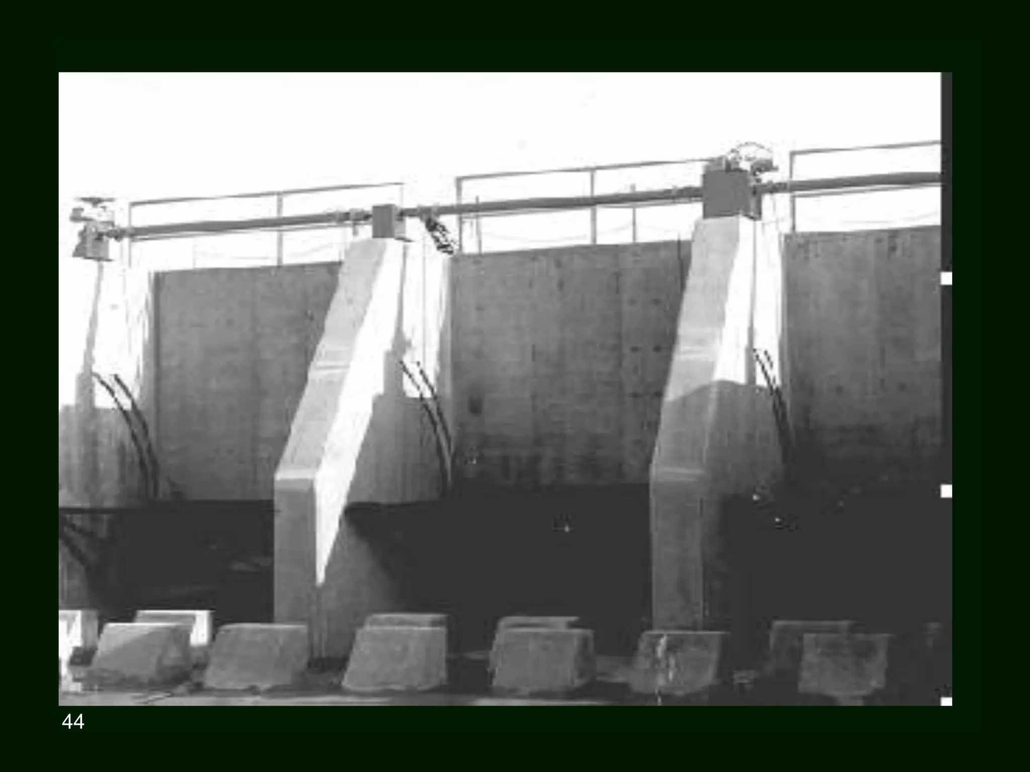
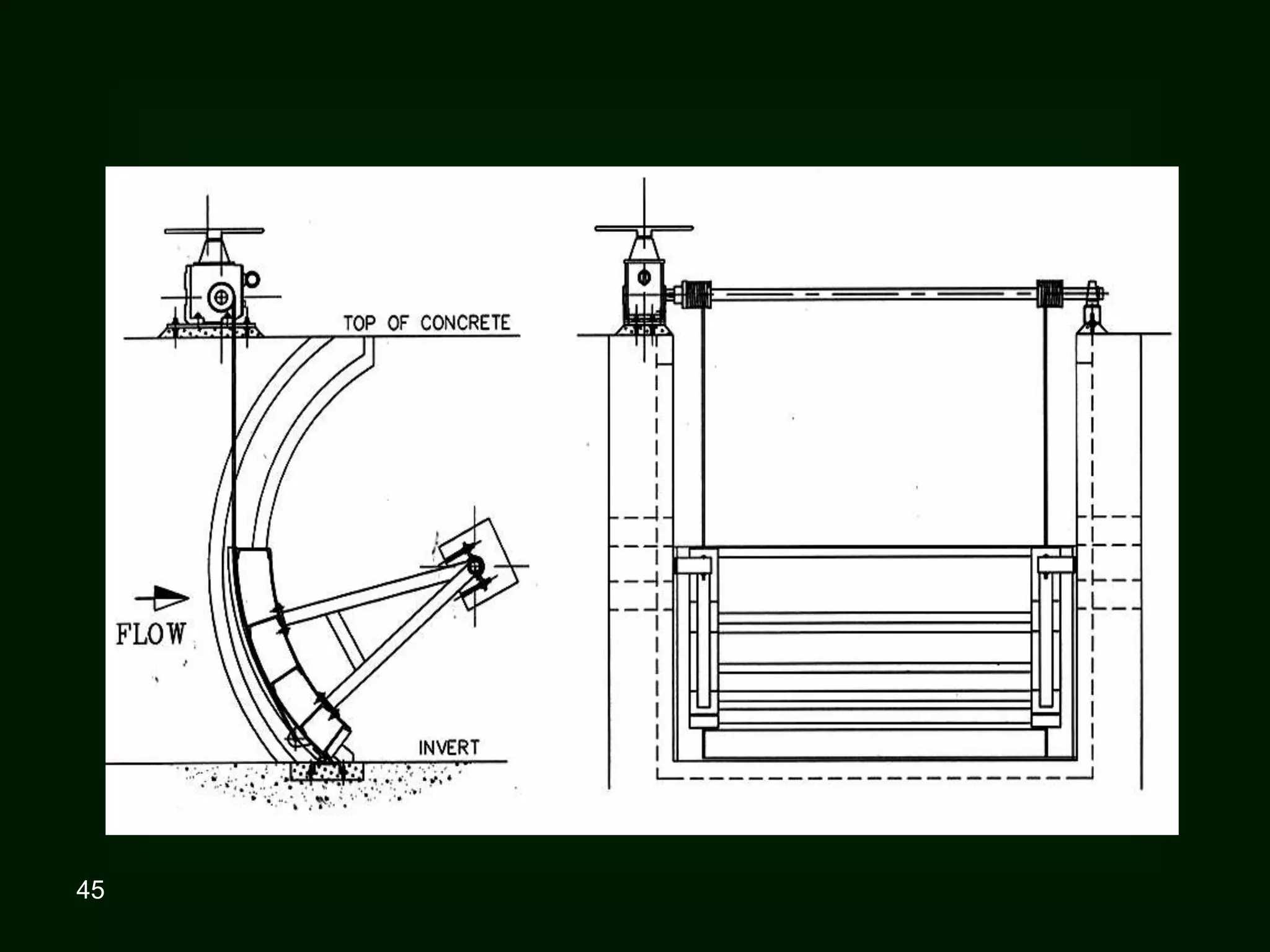
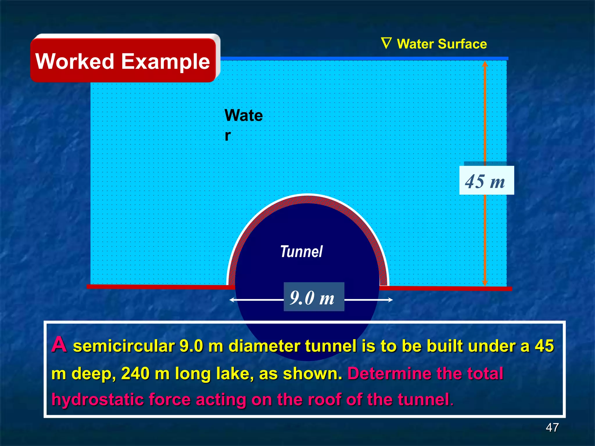
3. For regular shapes, equations are provided to calculate the hydrostatic forces and location of the center of pressure based on the surface dimensions and submergence depth. Examples of applying these concepts to dams, gates, and curved surfaces are also presented.
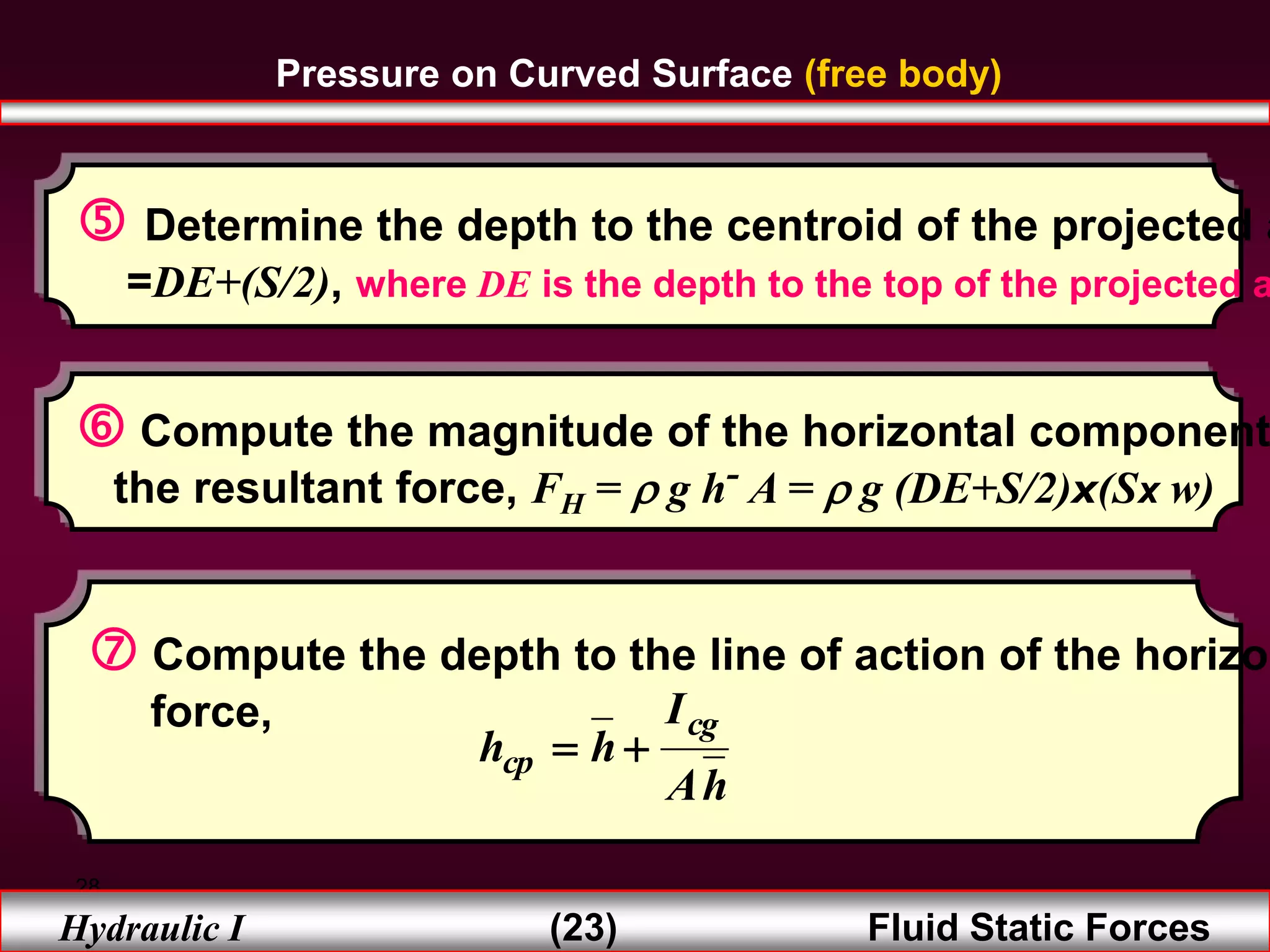
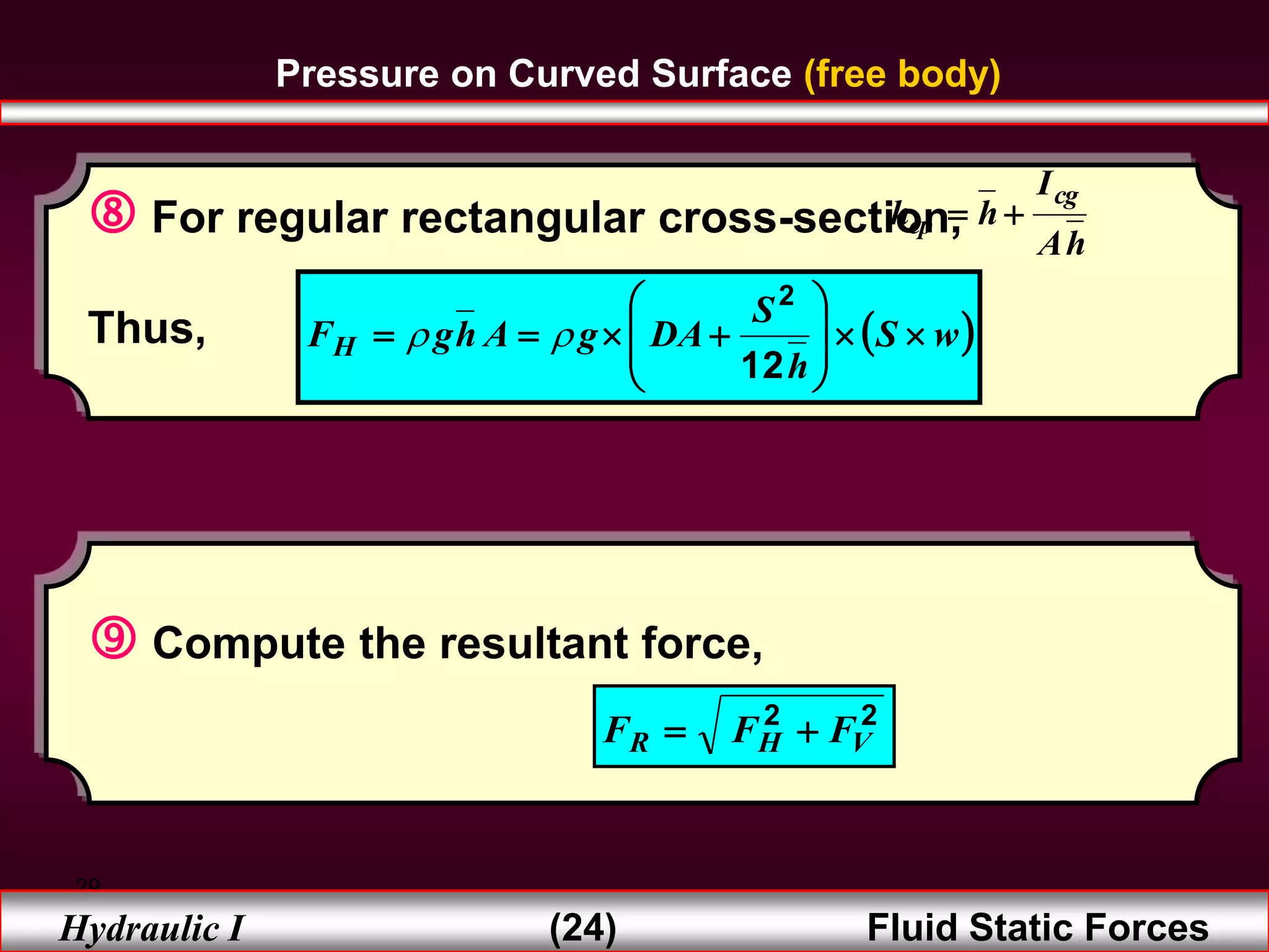
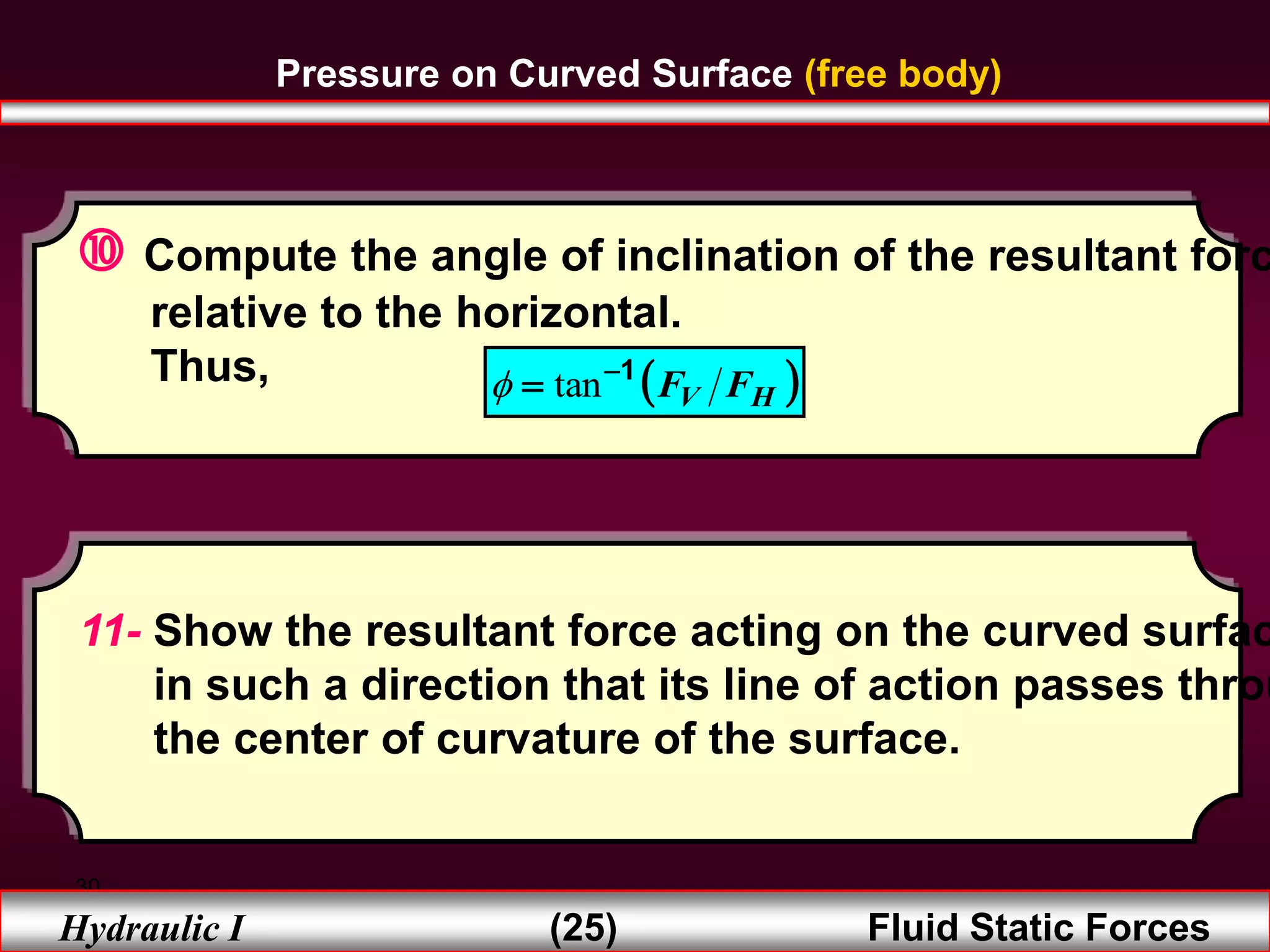
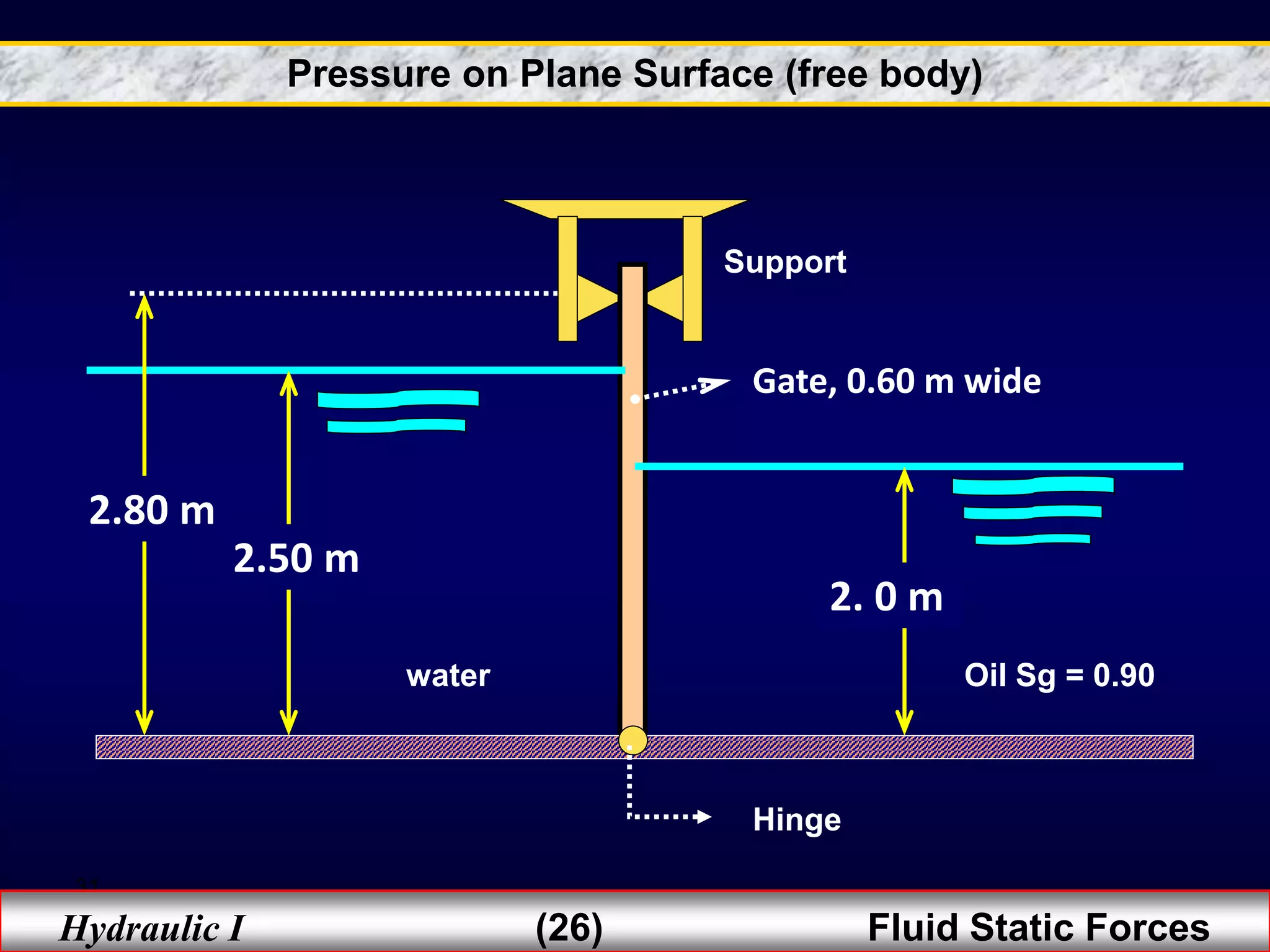


![Chapter 3 static forces on surfaces [compatibility mode]](https://cdn.slidesharecdn.com/ss_thumbnails/chapter-3-static-forces-on-surfaces-compatibility-mode-160214035852-thumbnail.jpg?width=640&height=640&fit=bounds)


![Chapter Four [Repaired].pptx](https://cdn.slidesharecdn.com/ss_thumbnails/chapterfourrepaired-230317125646-7f640ad0-thumbnail.jpg?width=640&height=640&fit=bounds)