Download to read offline
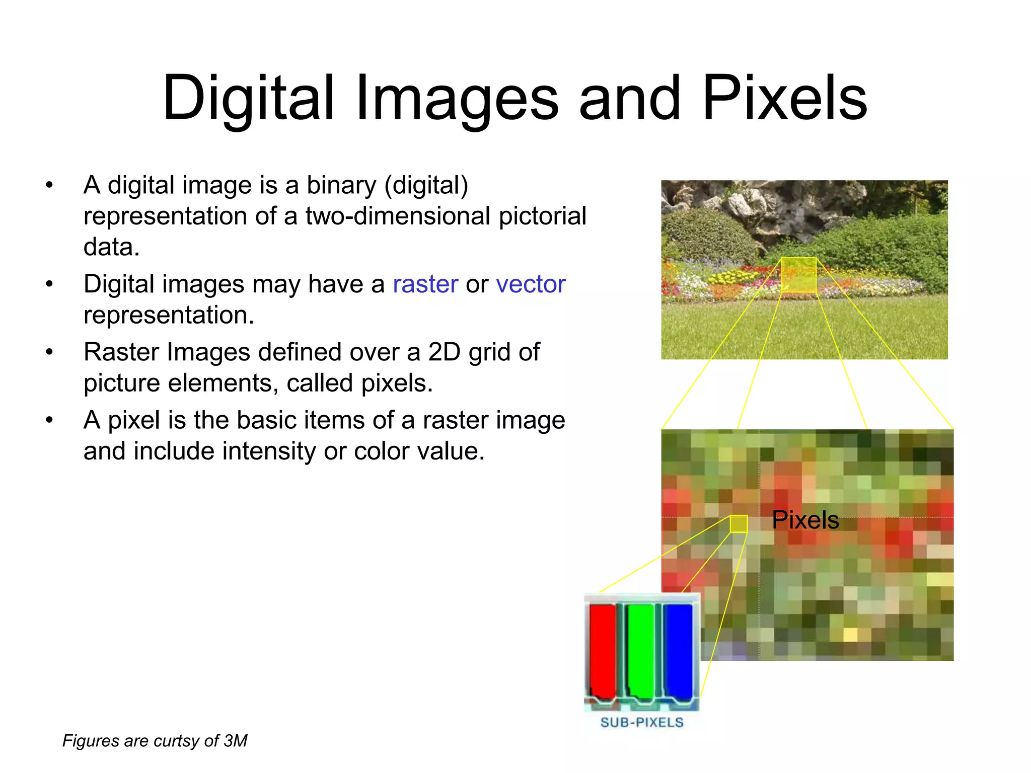
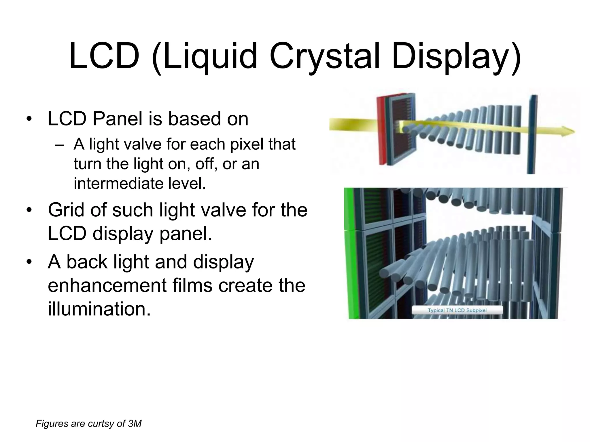
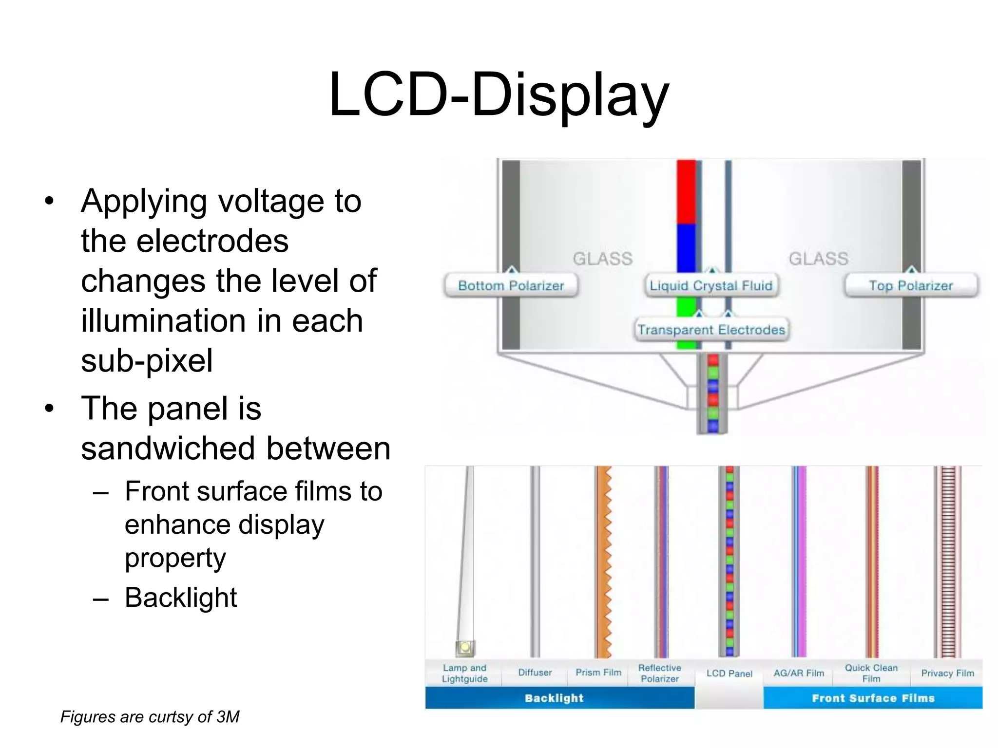
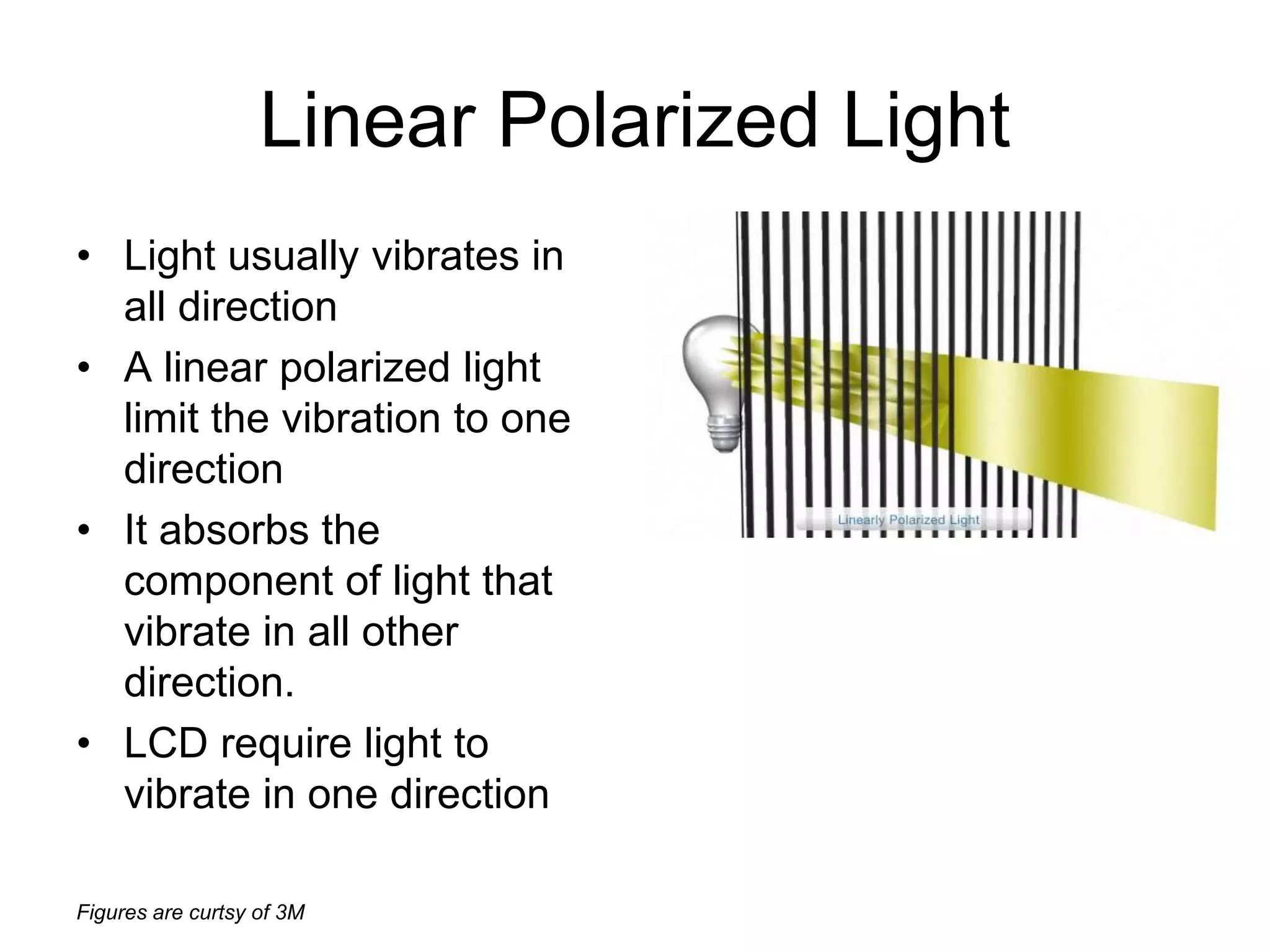
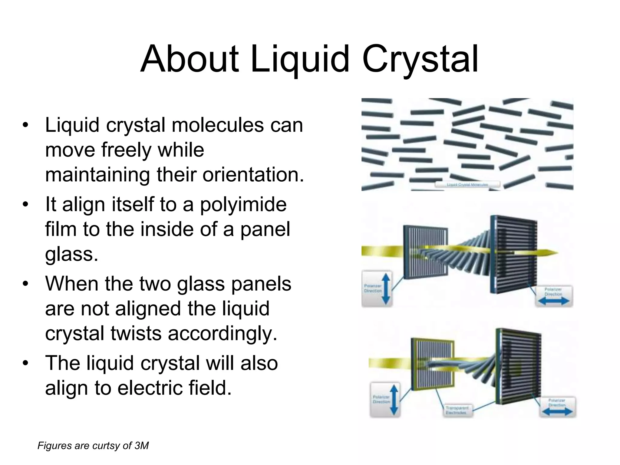
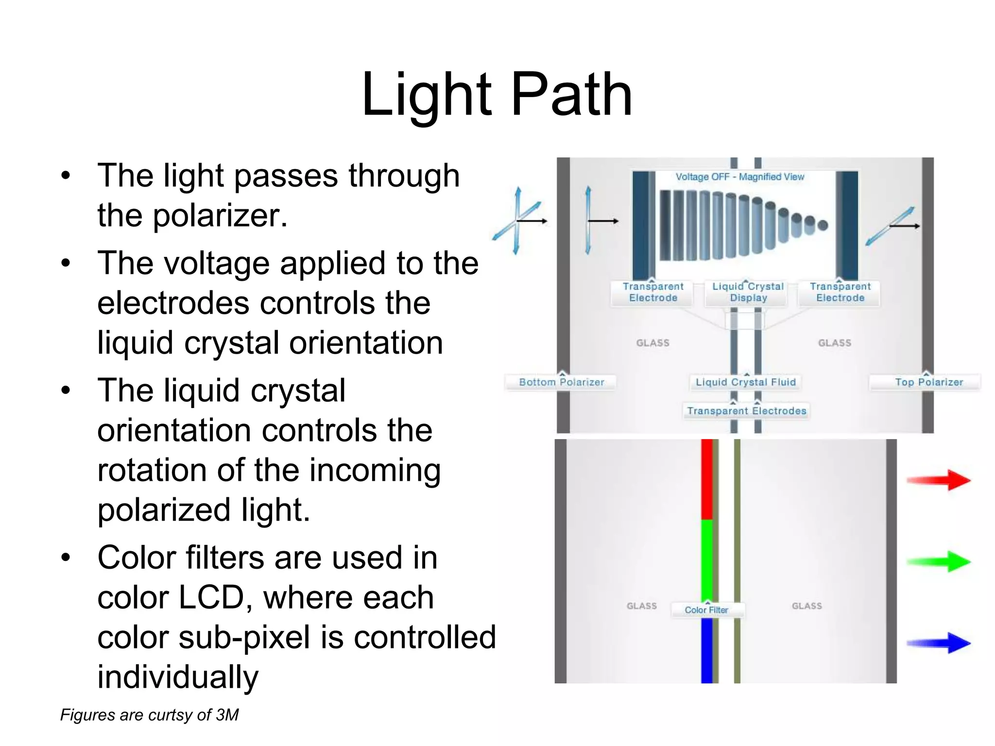
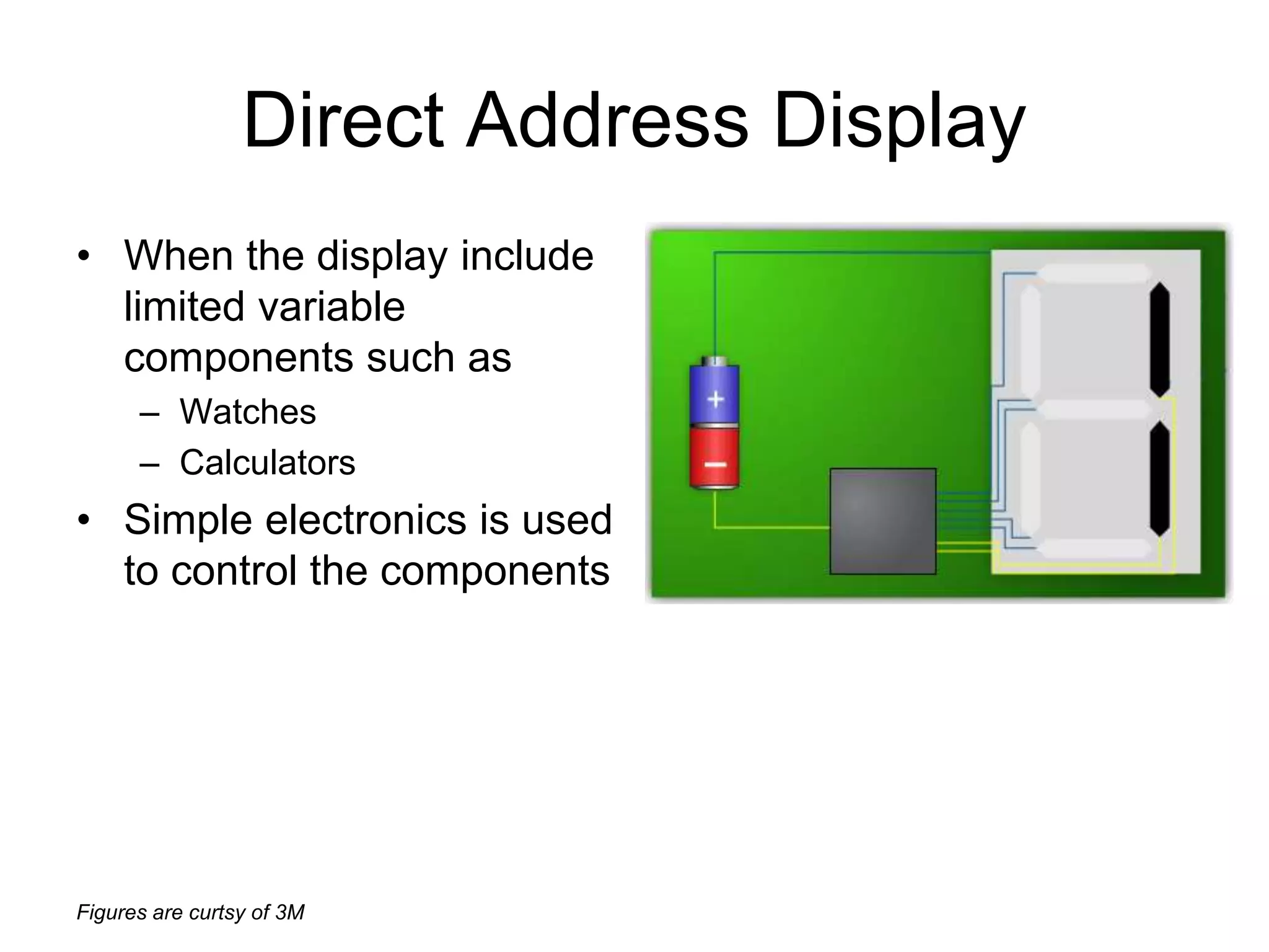
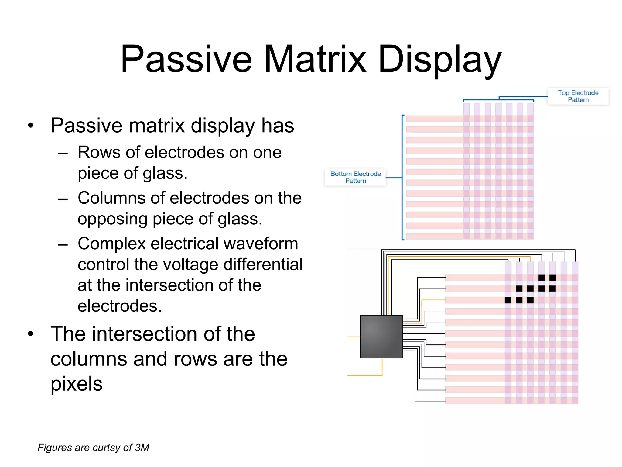
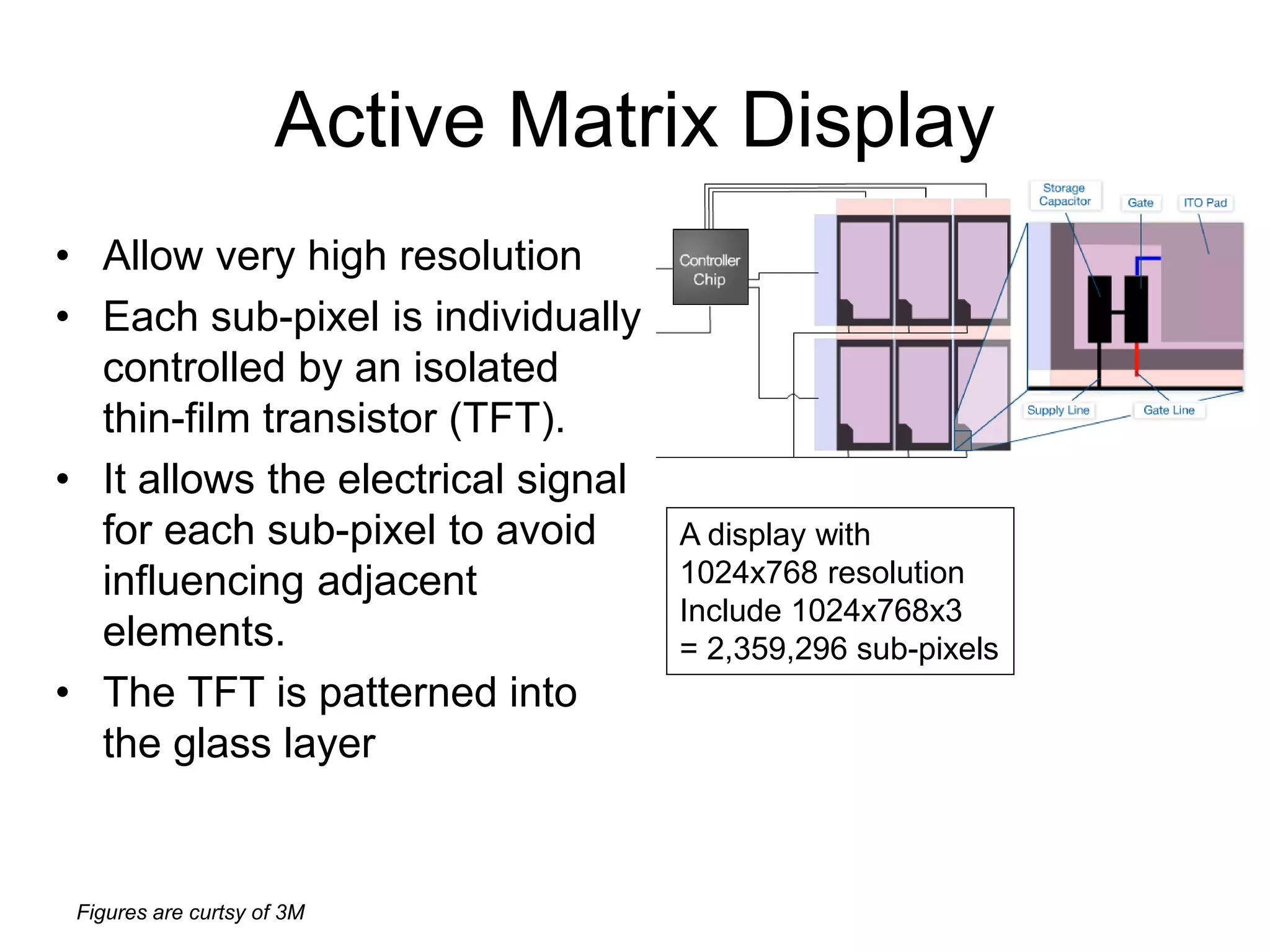
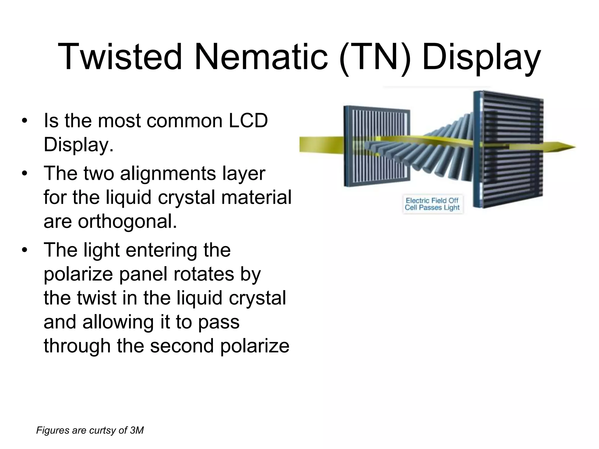
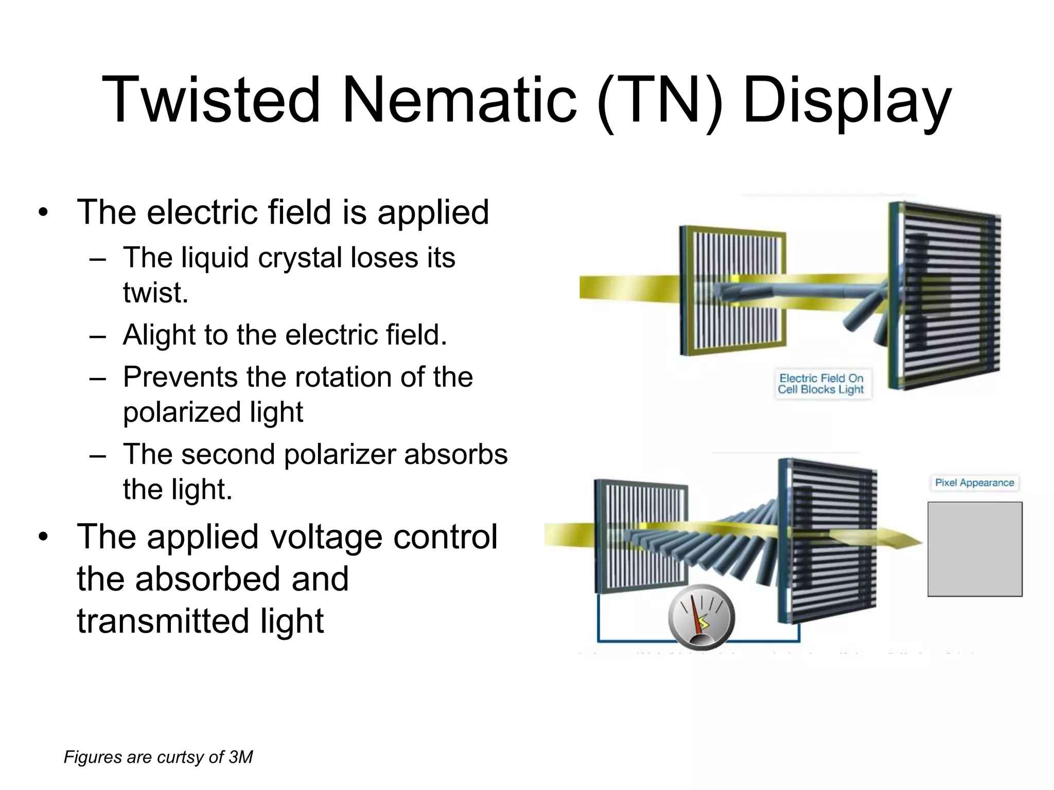
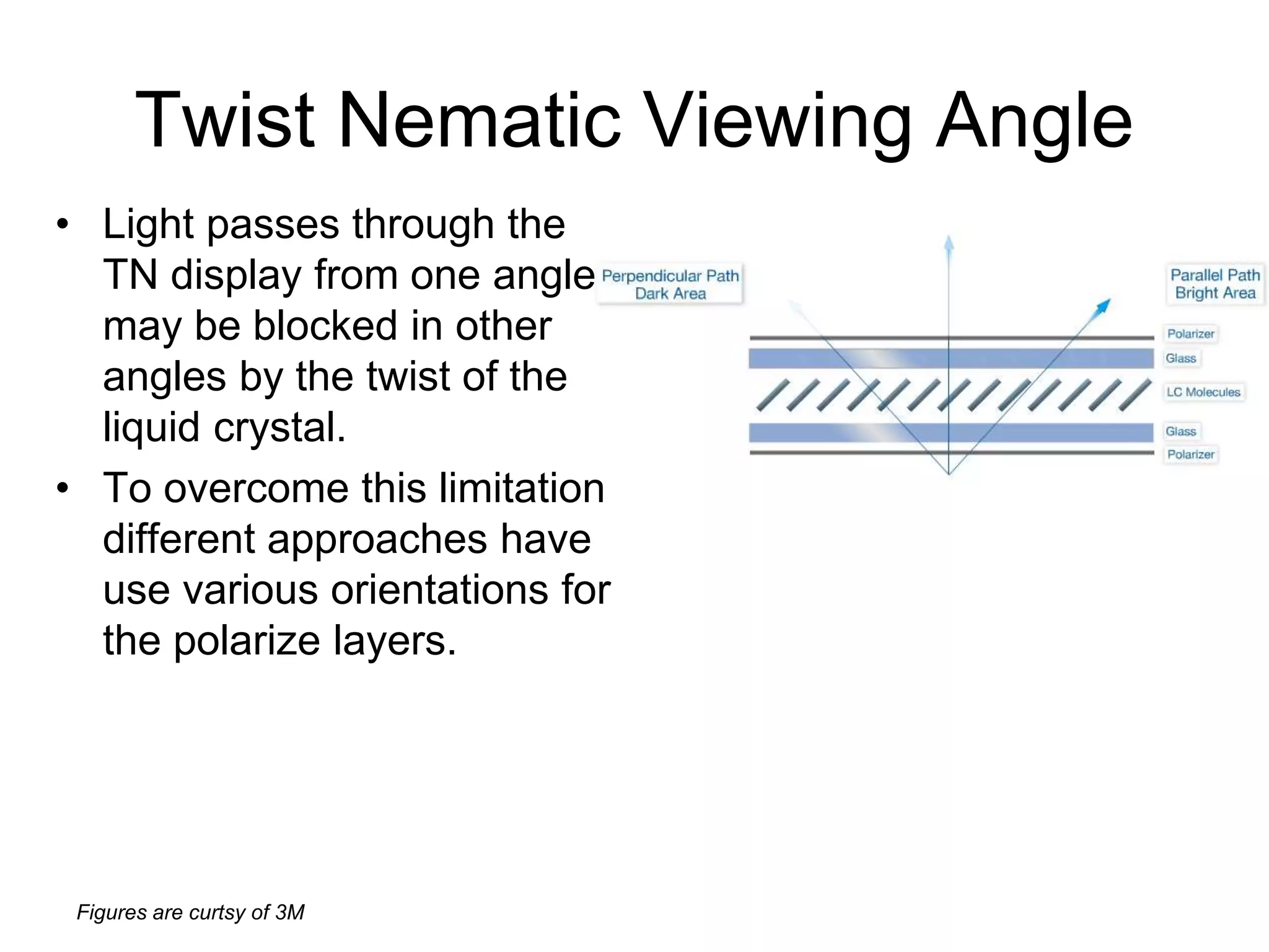
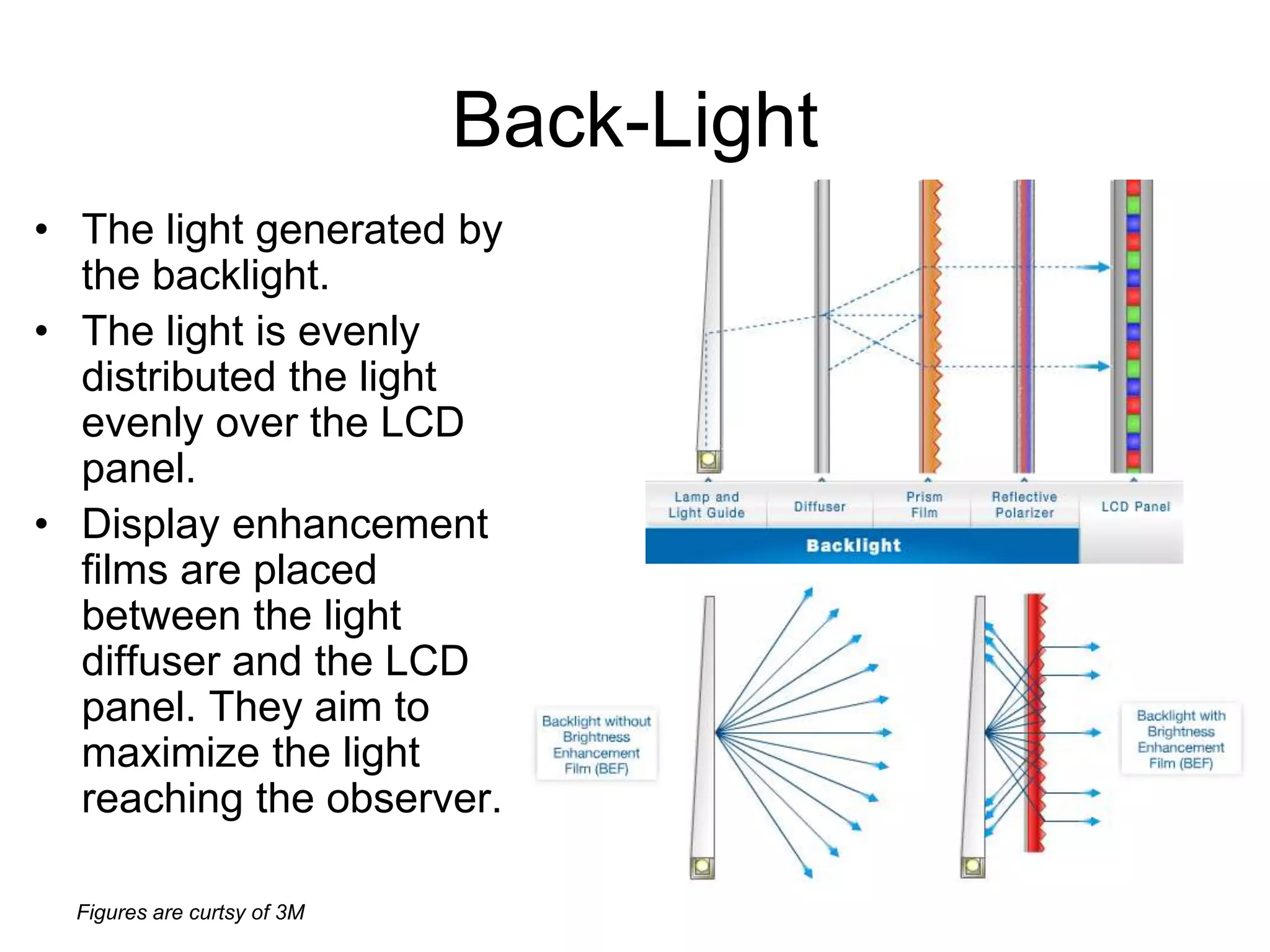

This document discusses LCD display technology. It describes how LCD panels use a grid of light valves called pixels to turn light on or off to form a digital image. Each pixel contains liquid crystals that can be manipulated by electric fields to control the polarization of light. Advanced LCDs use thin-film transistors to individually control large numbers of pixels in high-resolution active matrix displays. Various technologies are used to optimize the viewing angle and brightness of LCD displays.