TataKelola dan KamSiber Kecerdasan Buatan v022.pdf
Pc Open Del3
1. Chapter 15: Monitors and Displays 399
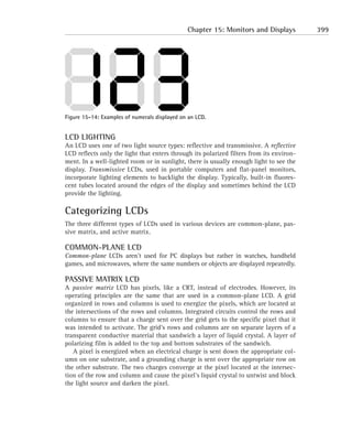
Figure 15-14: Examples of numerals displayed on an LCD.
LCD LIGHTING
An LCD uses one of two light source types: reflective and transmissive. A reflective
LCD reflects only the light that enters through its polarized filters from its environ-
ment. In a well-lighted room or in sunlight, there is usually enough light to see the
display. Transmissive LCDs, used in portable computers and flat-panel monitors,
incorporate lighting elements to backlight the display. Typically, built-in fluores-
cent tubes located around the edges of the display and sometimes behind the LCD
provide the lighting.
Categorizing LCDs
The three different types of LCDs used in various devices are common-plane, pas-
sive matrix, and active matrix.
COMMON-PLANE LCD
Common-plane LCDs aren’t used for PC displays but rather in watches, handheld
games, and microwaves, where the same numbers or objects are displayed repeatedly.
PASSIVE MATRIX LCD
A passive matrix LCD has pixels, like a CRT, instead of electrodes. However, its
operating principles are the same that are used in a common-plane LCD. A grid
organized in rows and columns is used to energize the pixels, which are located at
the intersections of the rows and columns. Integrated circuits control the rows and
columns to ensure that a charge sent over the grid gets to the specific pixel that it
was intended to activate. The grid’s rows and columns are on separate layers of a
transparent conductive material that sandwich a layer of liquid crystal. A layer of
polarizing film is added to the top and bottom substrates of the sandwich.
A pixel is energized when an electrical charge is sent down the appropriate col-
umn on one substrate, and a grounding charge is sent over the appropriate row on
the other substrate. The two charges converge at the pixel located at the intersec-
tion of the row and column and cause the pixel’s liquid crystal to untwist and block
the light source and darken the pixel.
2. 400 Part IV: Sight and Sound Systems
Another Passive Matrix Application
An application of passive matrix LCD technology is the portable stylus-based computer,
also known as the personal digital assistant (PDA) or palmtop computer. Although these
computers might have a keyboard, commands and data are typically entered through
the screen via a special non-writing pen or stylus. The display is covered by a
protective, plastic covering; beneath the display is a wire grid that recognizes the
movements of the stylus. The wire grid records the movements of the pen over the
grid’s intersections, which is similar to the technology behind touch-screens.
A passive matrix LCD has its disadvantages. Its refresh speed (the response time) is
slow, and the grid delivers electricity imprecisely to specific pixels. This latter prob-
lem can affect nearby pixels and create a fuzzy image or create contrast problems.
A passive matrix display uses one of two types of liquid crystal:
N Twisted nematic (TN): TN liquid crystal has a 90° twist and is used in low-
cost displays. It produces a black on gray or silver background. TN liquid
crystal is used primarily on consumer electronics and appliances.
N Supertwisted nematic (STN): Although its name sounds a bit like your
wacky brother-in-law, STN is the type of liquid crystal found on a
portable or handheld PC or a PDA. It is made with either a 180° or a 270°
twist, which gives it a much wider range of motion, making it more toler-
ant against any energy radiating from nearby pixels and allowing it to
provide more steps of color shadings. STN is used in both monochrome
and color displays.
Although not a type of liquid crystal, dual-scan STN (DSTN) is a process used
in some LCDs to double the number of lines refreshed and to cut the time to
refresh the display in half. This is accomplished by dividing the LCD into two
equal halves that are scanned simultaneously.
ACTIVE MATRIX LCD
The pixels on an active matrix LCD use thin-film transistors (TFTs), which is why
this type of LCD is often called a TFT display. TFTs are switching transistors and
capacitors etched in a matrix pattern on a glass substrate that forms one of the lay-
ers of the active matrix LCD. Each pixel consists of three TFTs, one for each of the
3. Chapter 15: Monitors and Displays 401
RGB colors, which can add up to quite a few transistors in the display. For example,
a VGA 640 x 480 color display uses 921,600 transistors; comparatively, a 1024 x
768 UVGA color display uses 2,359,296 transistors, all of which are etched into the
substrate glass. If a transistor is defective, it creates a bad pixel. TFT displays com-
monly have at least a few bad pixels.
An active matrix LCD addresses its pixels somewhat like a passive matrix.
However, when one row is addressed on the active matrix display, all the other rows
are switched off, and the charge is sent down the appropriate column. Because only
the addressed row is active, just the pixel at the intersection of the active row and
column is affected. The TFT’s capacitor holds the energy used to charge the pixel
until the next refresh cycle.
The color of the pixel is provided by color filters that lay over the areas con-
trolled by the pixel’s three TFTs. Colors are created by the amount of light allowed
to pass through the filters by each of the TFTs, which are controlled by the inten-
sity of the charge sent to them by the image control circuits.
As illustrated in Figure 15-15, the TFT’s control how much the liquid crystal ele-
ments open (untwist) to block the light passing through the color filters. In the sit-
uation shown in Figure 15-15, a small amount of the light source is being allowed
to pass through the red filter along with a wide open blue, but no light is being
passed through the green filter. Controlling the amount of electricity that flows to
the pixel manages the action of the liquid crystal and the amount of light allowed
to pass through the color filters. By controlling the light, active matrix screens are
able to display 256 levels of color brightness per pixel.
Comparing Viewing Angles
A display’s viewing angle measures how far above, below, and (more importantly) to
the side of the display that images on the screen can be accurately viewed. The
following table compares the viewing angles of the two LCD displays with a CRT. The
figure here illustrates the relative differences of the viewing angles of these displays.
Display Type Viewing Angle
Passive matrix LCD 49–100°
Active matrix LCD 90–120°
CRT 120–180°
Continued
4. 402 Part IV: Sight and Sound Systems
Comparing Viewing Angles (Continued)
Cathode ray tube
Active matrix LCD
Passive matrix LCD
The curvature of the screen has a lot to do with a display’s viewing angle, but next on
the list is the amount of contrast in the displayed image. An active matrix (TFT)
display has deeper color, clarity, and contrast over a passive matrix display. In the eye
of the viewer, LCD displays begin to lose their picture quality as the angle of view
increases because less of the display’s light (image) is able to reach the viewer.
Obviously, the viewing angle champion is the conventional CRT. However, a flat-screen
CRT might have a much lower viewing angle.
5. Chapter 15: Monitors and Displays 403
Red Green Blue
Figure 15-15: Controlling the color in an active matrix LCD.
Powering the Display
Monitors don’t run off the PC’s power supply, even if they are plugged into the
back of the PC power supply. Plugging a monitor into the back of the PC’s power
supply is the same as getting AC power straight from a wall outlet. The plug on the
back of the power supply is an AC power pass-through plug. A PC’s monitor uses
more power than all the other components of the PC added together. And because
of how it works, several power issues exist on monitors that don’t exist on a PC or
its power supply.
Managing power
In an effort to reduce the tremendous amount of energy being consumed by moni-
tors in active mode, governments and industry organizations have developed ini-
tiatives to reduce the amount of power consumed by PC monitors in general but
especially when they’re idle.
The U.S. Environmental Protection Agency (EPA) has the Energy Star program that
certifies monitors and personal computers that meet a guideline for reduced energy
consumption. This program certifies monitors that use less than 30 watts of power in
all power modes and reduce their power consumption by 99 percent when in sleep or
suspended mode. Most PCs sold today meet this standard, and you’ll see the Energy
Star logo displayed on the monitor during the boot sequence on these PCs.
Virtually all monitors on the market today are also compliant with VESA’s Display
Power Management System (DPMS) protocol. DPMS is used to power down parts of
the monitor and PC after they’ve been idle for a certain period of time. DPMS is a
Basic Input/Output System- (BIOS) supported protocol that can be enabled in the
Complementary Metal-Oxide Semiconductor (CMOS) settings of the PC.
6. 404 Part IV: Sight and Sound Systems
Degaussing the screen
The internal components of a CRT can become magnetized over time. If they do, it
can have a negative affect on the quality of the image produced by the monitor. If
the CRT becomes overly magnetized, color blotches can appear on the screen near
the edges and in the corners. A CRT can be magnetized in lots of ways, including
setting stereo speakers or other forms of magnets too close to the monitor (which
can also distort the display), bumping the monitor very hard, or moving the moni-
tor so that it’s positioned over a PC’s power supply.
The cure for magnetization of the CRT is degaussing. This term is derived from
the word gauss, which is a measure of magnetic force. Most better monitors have
built-in degaussing circuits that neutralize the CRT’s magnetization through a coil
of wire inside the monitor. The degaussing circuit is activated by either a manual
switch or automatically through the monitor’s controls.
On monitors with a manual degauss switch, pressing the switch activates a cir-
cuit that attempts to neutralize the CRT’s magnetization. The degauss process
involves some clicking and buzzing and takes only a few minutes to complete its
cycles.
Occasionally degaussing a monitor is a good idea, but avoid pushing the
degauss button repeatedly — once is typically enough to restore the moni-
tor’s color and sharpness. Overly degaussing a monitor can damage its
degauss circuits.
Most newer monitors do an automatic degauss when they’re powered up, which
is the static buzz and click that you hear when the monitor is powered up. If the
built-in degaussing circuits of the CRT don’t clear up the magnetization problem,
the monitor should be taken to a repair shop for manual degaussing with a special
degaussing tool.
Maintaining a Monitor
The life span of a PC monitor, given fairly regular preventive maintenance and
care, should be about five years. As I mention earlier, the monitor is the one part of
the PC that holds its value because the price of a monitor today is about what it was
two to three years ago on a price-per-feature basis. As long as the monitor is still
doing its job, why replace it? Usually monitors are purchased in tandem with the
PC, staying paired as long as both work. However, if the processor dies, the moni-
tor can be used with a different system.
The user — and most technicians, for that matter — should never attempt to repair a
monitor for circuitry or electrical problems. Only the manufacturer or an authorized
7. Chapter 15: Monitors and Displays 405
repair shop should repair any monitor, whether CRT or LCD. Before you authorize any
repairs, however, compare the cost estimate of the repair with that of purchasing a
new monitor. In most situations, the cost to repair a monitor is relatively inexpensive,
but if the monitor needs a new CRT or LCD, buying a new monitor could be a better
investment.
Keeping safe
Rule number one: Never — repeat, never — open the monitor’s case. All repairs that
require opening or removing the monitor’s case should be performed at a repair
shop that’s properly equipped to work on monitors.
Rule number two: Should you choose to risk your life by ignoring rule number
one and open the monitor’s case to work on it, absolutely do not wear an ESD wrist
strap. If you do, you become the grounding circuit for all stored and static electric-
ity in the monitor.
Never attempt to work inside the monitor’s case. So what if you have to buy
a new monitor? You have to decide whether your life is worth saving two or
three hundred dollars.
Another safety issue, although somewhat controversial, is the potential harm
from electromagnetic monitor emissions.
ELECTRICAL SHOCK
The reason for the above warnings and gloom-and-doom (which cannot be empha-
sized enough) is that inside the monitor is a very large capacitor, which is an elec-
tronic device that holds power and uses it to regulate the power stream that it
receives. Remember that the monitor isn’t powered by the PC’s power supply; it’s
plugged directly into an AC outlet. The monitor has a power supply much like the
one in the PC itself. In this power supply is a large capacitor that stores enough
electrical power to cause you very serious harm, even when the monitor is off and
unplugged. The capacitor has a capacity of around 1,000 microfarads to absorb
power spikes and fill in low-voltage events.
ELECTROMAGNETIC EMISSIONS
A CRT emits small amounts of Very Low Frequency (VLF) and Extremely Low
Frequency (ELF) electromagnetic radiation, and a debate is ongoing as to whether
this radiation is harmful to PC users. VLF and ELF aren’t lethal emissions like an X-
ray or a gamma ray, but many experts believe that they could be harmful after
extended exposure periods.
Most of the CRT’s radiation is emitted from its back and sides, with a very small
amount emanating from the screen. The radiation doesn’t carry far and is usually
totally gone a few feet from the monitor. As a precaution, users should sit at an
8. 406 Part IV: Sight and Sound Systems
arm’s length from the monitor screen to protect their eyes as well as to put them-
selves a relatively safe distance from the radiation emissions. Spacing monitors
with a few feet of open space on their back and sides should keep everyone safe.
The debate on radiation emissions is that prolonged exposure can cause
cancer, leukemia, and pregnancy complications, including miscarriage and
birth defects. Nothing has been proven conclusively on whether this is fact
or fear yet, but it is always better to err on the safe side. In fact, the Swedish
government has created an organization to develop monitor standards that
safeguard against monitor emissions. If you wish to purchase a monitor that
conforms to these standards or check whether your existing monitor con-
forms, look for a TCO (which stands for the Swedish words that mean The
Swedish Confederation of Professional Employees) certification. There have
been four versions of these standards since its inception in 1991, with the
latest being TCO,‘99.TCO ‘0x is now pending.
Performing preventive maintenance
The life of a monitor can be extended with a regular program of preventive main-
tenance. Here are some things you can do to prevent overheating and magnetiza-
tion, as well as some cleaning tips. Most of these tips apply to CRT monitors but
can also be applied to an LCD display. For an LCD monitor, check its documentation
for cleaning and care tips. In these and all other maintenance activities on PCs, let
common sense be your guide.
N Keep a free space buffer of a few feet in each direction around a CRT
monitor. This helps its cooling system to work efficiently as well as pro-
tect other users from radiation emissions.
N Never stack anything on top of the monitor or closely around it. Blocking
the monitor’s airflow will shorten the life of the CRT by causing it to
overheat. The CRT is the most expensive part of the monitor to replace.
Never place any form of magnetic media (diskettes, tapes, and so on) on
top of the monitor . . . unless you wish to erase them. Remember that a
very large magnet and lots of electromagnetic forces are inside the case.
N Never place heavy items on the monitor’s top. This can cause the case to
crack or at least flex and cause something inside the case to short.
N Keep the monitor (and PC) at a distance from heat sources, damp environ-
ments, magnets (including those in standard PC or stereo speakers),
motors, or areas in which static electricity is a problem. Magnets can
affect the quality of the display.
9. Chapter 15: Monitors and Displays 407
Okay, so some monitors come with side-mounting speakers. Typically, these
speakers have been constructed with special magnetic shielding to prevent
any electromagnetic interference with the monitor.
N Use the power cord supplied with the monitor. This cord is usually espe-
cially designed to handle your monitor’s voltage. If you misplace it,
obtain a replacement from the manufacturer or a dealer for that brand of
monitor. Hint: Don’t confuse the PC’s power cord with the monitor’s cord
when moving the system.
N The monitor’s case should only be cleaned with a damp, lint-free cloth.
Always unplug the monitor before cleaning it or using any water-based
cleaning solutions on it. The monitor’s screen can be cleaned with the
same cloth and with a little diluted glass cleaner. Don’t spray any liquids
on the screen; instead, spray the cleaner on the cloth and then wipe the
screen clean. Always be sure to wipe the screen completely dry. Avoid
strong degreasers or ammonia-based cleaners because they can affect the
screen’s glass and even the colors of the display.
N Keep the monitor on its original base/foot. The stand that shipped with the
monitor is actually engineered as a part of the cooling system. If you
remove it and set the monitor on its case bottom, you run the risk of
blocking the air vents on the bottom of the case. The monitor needs to sit
up a bit to allow proper airflow for the cooling system.
N Avoid touching the screen with your hands. Oil and dirt from your hands
are very hard to remove from the screen.
The monitor is blank or has no picture
A variety of problems can cause the monitor to be blank or dark or appear to be
dead. Use the following steps to debug this problem:
1. Verify that the monitor is connected to a power source and is receiving
power.
Most newer monitors have a small light on their front that indicates when
the power is on.
2. Verify that the monitor is connected to the PC’s video card and that the
connection is snug.
If the screen is white or gray (instead of black) and you hear a buzzing or
high-pitched whine coming from the monitor, the monitor is probably not
connected to the video card.
10. 408 Part IV: Sight and Sound Systems
Check the connection at the monitor end if the monitor uses a two-end
video cable. Check the pins in the cable connectors for bent or broken
pins before reconnecting them.
3. Check that the brightness and contrast controls haven’t been turned all
the way up, which results in a dark screen.
If these two controls are okay, check a few of the other controls, such as
the geometry settings (height, width, and trapezoidal shape and location),
because some combinations of settings will also darken the display. Use
the monitor’s documentation to locate and use the monitor’s adjusting
controls.
4. Reboot the PC, listening for beep codes and watching for error messages
from the POST.
If a single beep sounds and the PC seems to be continuing with the boot,
the problem is most likely in the monitor. Otherwise, the problem might
be that the boot is hanging up before the video BIOS and device drivers
were loaded. Verify with your system BIOS or motherboard documentation
what the beep code is for video adapter problems and listen carefully for
that or another beep code indicating a hardware problem.
See Chapter 4 for more information on the system BIOS and its beep codes.
5. Replace the monitor with a known-good monitor.
If the display appears, the original monitor is bad. Otherwise, replace the
video card and continue troubleshooting.
The monitor has display but isn’t functioning
properly
This is probably a device driver problem, a video card problem, or a failing moni-
tor. Use the steps in the preceding section to troubleshoot the latter two but only
after following the steps here to check the configuration of the monitor on the PC:
1. Verify the monitor’s settings from the Windows Device Manager: Right-
click My Computer and then choose Properties ¡ System Properties ¡
Hardware Tab ¡ Device Manager.
2. Drill down through in the device tree to find the video card (graphics
adapter). Highlight the video card’s device entry and then click the
11. Chapter 15: Monitors and Displays 409
Properties button (on Windows 2000 or Windows XP, just double-click the
device name).
On the device’s Properties window that opens, verify the driver and
the system resources assigned to the video card. Resolve any resource
conflicts.
See Chapter 5 for more information on resolving resource conflicts.
3. Check the video card’s manufacturer for any updates or newer device dri-
vers and install them.
Manufacturers’ Web sites are a good place to start.
4. If all is well, make sure that the monitor is listed in the Windows system
settings. Right-click the desktop in an open space; from the menu that
appears, choose Properties to open the Display Properties window. (The
Display icon on the Control Panel also opens this window.) Select the
Settings tab and click the Advanced button there to open the video card
Properties window, shown in Figure 15-16.
Figure 15-16: Check the monitor installed on the
video card’s Properties window.
12. 410 Part IV: Sight and Sound Systems
5. Choose the Monitor tab. If the monitor listed is not the type in use, click
the Change button (upper-right side of the window) to open the Update
Device Driver Wizard (shown in Figure 15-17), which will guide you
through the installation of the proper device driver.
If a disk came with the monitor, have it handy to use. When asked to
choose a driver, click the Have Disk button.
Figure 15-17: The Windows Update Device Driver Wizard.
The monitor doesn’t power on
If the monitor’s power indicator light on its front bezel is lighted, the problem is
probably not a power source problem. Use the steps in the earlier section “The mon-
itor is blank or has no picture” to verify that the source of the problem is not else-
where. If that doesn’t find the problem, check the monitor on a different PC to
verify that the video card isn’t the problem. Otherwise, the monitor might have
internal power or circuitry issues, requiring a trip to the repair shop.
To check the power, use the following steps:
1. Push the monitor’s power button on and off a few times to make sure that
the button isn’t just stuck.
If the monitor powers up, you’ll hear the static buzz and clicking associ-
ated with the automatic degauss and other start-up steps performed by the
monitor.
2. If the power button isn’t the problem, check that the power cord is snugly
seated in its connector.
The power cord on many monitors is a specially designed cord. Check the
documentation to see whether the monitor uses a special power cord and
how it is identified. If needed, verify that the correct cable is in use.
13. Chapter 15: Monitors and Displays 411
3. Check the fuse on the back of the monitor.
It probably looks like a small black knob with the word Fuse on the cap. If
the fuse is bad (the element inside the fuse is broken or burnt), replace it.
You can get replacement fuses at most computer or electronics shops. If
the fuse frequently needs replacing, you have an internal electrical prob-
lem, and the monitor should go to the repair shop.
4. If the monitor is an older EGA (or older) monitor, it might be plugged
directly into the back of the power supply. If this is the case, the PC must
be powered up before the monitor will have power.
The power supply pass-through plug could be defective.
5. If the monitor is plugged into a power strip, make sure that it’s switched
on and working.
Plug the monitor into another AC source to verify the power source.
Changing the color depth or resolution
To change the color depth (bit depth) or resolution settings for the monitor on a
Windows PC or notebook computer, use the following steps:
1. Right-click in an empty space on the desktop to display the menu shown
in Figure 15-18.
Figure 15-18: The Windows desktop pop-up menu.
2. Choose Properties to open the Display Properties window shown in Figure
15-19.
3. Select the Settings tab.
Toward the bottom of the Settings tab are two side-by-side settings that
control the color depth (Colors) and the screen resolution (Screen Area), as
shown in Figure 15-20.
14. 412 Part IV: Sight and Sound Systems
Figure 15-19: The Windows Display Properties window.
Figure 15-20: The Colors and Screen Area settings on
the Display Properties Settings window.
4. Change the Screen Area setting to its lowest value (move the slider all the
way to the left).
It should be 640 x 480.
5. From the Colors drop-down list, change the color depth to 256 Colors (8-bit).
These settings are the VGA standard settings.
15. Chapter 15: Monitors and Displays 413
6. Click the Apply button and do not restart the system when asked.
Unless these settings were how your monitor was set to begin with, the
displayed image should be constructed of much larger elements and might
not all fit onto the display.
7. Reopen the Display Properties window, change the resolution (Screen
Area) and color depth (Colors) to the highest settings available, and then
accept the settings without restarting your PC.
The display should be much more detailed, and all the elements should be
much smaller than under VGA standard settings.
8. Reset the Display Properties to their original settings unless you prefer
their new values. Otherwise, just click OK to apply the new settings.
Setting the refresh rate
To set the refresh rate on your monitor or to check its setting, do the following:
1. Follow the steps used in the preceding section to display the Display
Properties window.
2. Click the Advanced button to display the Properties window for the video
adapter in your PC.
3. From the Adapter tab, select the Refresh rate from a list box located in the
middle of the window.
Most monitors have a range of refresh rates that they support.The monitor’s
documentation should recommend its best refresh rate setting. On most
Windows 9x, Me, Windows 2000, or Windows XP PCs, the refresh rate should
be set to Optimal.
Recovering from an incorrect refresh rate
If you change the refresh rate and the result is a distorted or blurry image, reboot
your PC into Windows Safe Mode and reset the refresh rate using the steps in the
preceding project.
See Chapter 27 for the process used to boot a PC into Safe Mode.
16. 414 Part IV: Sight and Sound Systems
The monitor goes blank and shuts off when idle
If your monitor goes blank and shuts off when idle, the monitor has its energy-
saving settings activated. Use the following steps to adjust or turn off these fea-
tures:
1. Open the Display Properties window by right-clicking the desktop in an
open area and choosing Properties from the menu that appears.
2. From the Display Properties window that appears, choose the Screen
Saver tab.
If your monitor contains energy-saving features, the lower quarter of the
window has an area with the Energy Star logo and a Settings button, as
shown in Figure 15-21.
Figure 15-21: The Energy Star area on the Screen Saver tab.
3. Click the Settings button to open the Power Management Properties win-
dow, shown in Figure 15-22.
From this window, you can set the period of inactivity for each of the
devices included in the energy-saving controls. The times available are in
the list boxes for each device.
To save a new custom energy configuration, use the Save As function.
Selecting Never from the menus turns off the energy-savings feature for a
device.
17. Chapter 15: Monitors and Displays 415
Figure 15-22: The Power Management Properties window is
used to set the energy-savings parameters of the monitor.
Disposing of a CRT monitor
As much as 70 percent of a CRT’s components contain lead, which is why CRTs
come under the Land Disposal Ban Program of the Resource Conservation and
Recovery Act (RCRA). This law requires CRTs to be disposed of using a very pre-
scriptive procedure. You can’t just throw them in the dumpster or the landfill.
According to the RCRA regulations, a CRT must be dismantled, crushed, and encap-
sulated in cement to be disposed of properly. Because this isn’t something that you
should do yourself (even if you could), salvage companies exist that specialize in
CRT and computer disposals and will do so for a small fee. By the way, this law
covers TV sets as well.
18.
19. Chapter 16
Audio and Image Capture
Devices
IN THIS CHAPTER
Not long ago, the only sounds coming from a PC, aside from a noisy fan or hard
drive, emanated from its tiny, tinny system speaker mounted somewhere inside the
case. This PC speaker was intended primarily to emit beeps, squawks, and whistles
to alert the user of diagnostic Power-On Self-Test (POST) messages and error and
other operating system alerts.
Today’s sound systems, which have expanded the audio world of the PC near
high fidelity, are standard equipment on new PCs. The audio or sound system of
today’s PC range in complexity from simple playback devices for games and system
sounds all the way to full-fledged Digital Audio Workstations (DAW), which are
used in professional audio and video production and post-production work. In this
chapter, I cover the following:
N Resolving sound system problems
N Dealing with CD audio issues
N Connecting a CD-ROM or DVD to a sound card
N Solving system resource conflicts
N Connecting a scanner to your PC
N Downloading images from a digital camera
WITH THE ADVANCEMENT OF THE SOUND RECORDING and reproduction capabilities of the
PC, along with the advancement of its video and multiple media playback capabil-
ities, the PC is finally beginning to fulfill the promise of a true multimedia device.
This chapter explores the components of the PC sound system and looks at a few of
the devices used to capture and import video images into the PC.
Examining the PC Sound System
Just like that fancy component stereo system that you’ve always wanted, the PC’s
sound system is made up of a number of different pieces. Each of the sound system
components, which I discuss in the following sections, performs a certain function
417
in the sound capture and playback abilities of the PC.
20. 418 Part IV: Sight and Sound Systems
Audio Software Publishers
Some of the better-known audio software publishers include
N Cakewalk: www.cakewalk.com
N Microsoft: www.microsoft.com/windows/windowsmedia
N Nullsoft: www.winamp.com
N RealNetworks: www.real.com
N Sonic Foundry: www.sonicfoundry.com
N Steinberg: www.steinberg.net
N Waves: www.waves.com
The primary components of a PC sound system are the following:
N Amplifier: After digital audio has been converted into an audible signal, it
has to be amplified before it can be played back on speakers. Most sound
cards include a weak amplifier capable of driving a set of headphones or
small passive (unpowered) PC speakers. Many PC speaker systems inte-
grate an amplifier into one or both of the speaker enclosures, taking the
burden of amplification off the sound card. With the correct cabling, the
signal from a sound card can be routed to any stereo or home theater sys-
tem, creating the possibility of true audiophile-quality sound from a PC.
In a DAW configuration, the signal is often routed through a mixing con-
sole before it’s amplified.
N Audio software: With the exception of the basic playback controls on the
front of some CD-ROM drives, most PC audio operations are controlled by
software. Microsoft’s Windows family of operating systems, as well as
many distributions of Linux, include basic tools for recording, playing,
and mixing audio from different sources. Advanced tools for recording
and manipulating digital audio are available from a variety of vendors.
N Magnetic shielding: Dedicated PC speaker systems differ from conven-
tional home-stereo speakers in an important way: Because they are typi-
cally placed fairly close to the computer monitor, PC speakers must be
magnetically shielded to avoid distorting the image on the screen and
ultimately damaging the monitor. Therefore, caution should be used when
configuring a PC audio system with components not specifically designed
for PC audio.
21. Chapter 16: Audio and Image Capture Devices 419
N Sound card: The sound card combines into a single unit all of the inputs,
outputs, and signal processors (digital-to-analog converter [DAC] and
analog-to-digital converter [ADC]) required to convert audio information
to and from digital form. Traditionally packaged as an Industry Standard
Architecture (ISA) or Peripheral Component Interconnect (PCI) adapter
card, there has been a recent trend toward mounting an integrated audio
chip directly on the motherboard, thus eliminating the need for a separate
device to handle audio.
N Speakers: PC speakers come in a wide range of configurations, from small
passive systems powered by the sound card’s headphone output to active
(amplified) 3-way and surround systems that would rival many home the-
aters. Some computer monitors have integrated speakers either incorpo-
rated into the bezel or designed to snap on and off the sides of the
monitor.
A recent development in PC audio is the Universal Serial Bus (USB) speaker
system. USB speaker systems don’t require a separate sound card. Digital
audio is sent directly to the speakers via the USB cable, and all signal pro-
cessing is done within the speaker enclosure itself, external to the PC. This
has a few advantages, including reducing the potential for audible interfer-
ence (hum or static) from other PC components. One disadvantage of USB
speakers is that they don’t provide a way to connect to the analog output of
a CD-ROM or DVD player. (See “Connecting a CD-ROM or DVD to a sound
card” later in this chapter.)
Taking a Closer Listen to Sound
Cards
The sound card combines the components required to transfer sound into and out
of a PC, including the following:
N Analog inputs: Most sound cards have separate line-level and mic-level
inputs. Line-level inputs are designed to either accept a signal from an
electronic source (such as a CD player or tape deck) or direct input from a
musical instrument (like a synthesizer). Mic-level inputs are designed to
accept the much lower voltage signal generated by a microphone or an
unamplified electric guitar. Professional sound cards for DAW applications
often have one or more stereo pairs of analog inputs for recording
22. 420 Part IV: Sight and Sound Systems
multiple channels simultaneously. The most common type of connector
for analog input is a standard 1⁄ 8" phone jack identical to those found on a
portable stereo. More specialized sound cards might include left and right
stereo RCA (you know, RCA as in RCA-Victor) jacks or 1⁄ 4" phone jacks in
order to be more compatible with professional studio gear.
N Analog outputs: Two analog outputs are frequently found on a sound
card. One’s a small amplifier, capable of driving a pair of headphones or
passive speakers, powers one that’s often identified as Phones Out/Speaker
Out. Another, usually called Line Out, is designed to send a line-level sig-
nal to an input such as that found on a home stereo receiver. Professional
sound cards for DAW applications commonly have one or more stereo
pairs of analog outputs for playing back multiple channels simultane-
ously. As with the inputs, 1⁄ 8" phone jacks are most common, but some
cards use RCA or 1⁄ 4" phone jacks.
N Analog-to-digital converter (ADC): The ADC converts analog audio infor-
mation, such as a voice or a musical instrument, into digital data that can
be stored and edited on a PC.
N Digital input/output (I/O): Once found only on high-end professional
sound cards, digital interfaces are beginning to show up on consumer
sound cards as well. Digital I/O makes it possible to transfer data to and
from digital devices such as MiniDisc and Digital Audio Tape (DAT)
machines without ever leaving the digital domain. This eliminates the
potential for signal degradation that accompanies the use of a DAC or
ADC. The most common types of digital interfaces found on sound cards
are Sony/Philips Digital Interface (S/P-DIF) and Audio Engineering
Society/European Broadcasting Union (AES/EBU).
N Digital Signal Processor (DSP): Another feature formerly found only on
high-end sound cards, DSPs are finding their way to less expensive cards
as well. DSPs can serve a variety of functions, but the goal is always the
same: to reduce the burden on the computer’s CPU when processing
audio. Among the tasks performed by DSP chips are resampling (which
reduces the size of the audio file without reducing the sound quality) and
digital effects (such as reverb and echo).
N Digital-to-analog converter (DAC): The DAC converts audio data stored on
a hard drive or other medium into audible information that can be played
back on speakers or headphones.
N Game/Musical Instrument Digital Interface (MIDI) port: This versatile
connector found on many sound cards is most often used for game con-
trollers such as joysticks or gamepads. With a special cable, this port can
be connected to any external MIDI device in order to send and receive
MIDI data. Most sound card MIDI interfaces are designed to emulate the
MPU-401 interface developed by Roland.
23. Chapter 16: Audio and Image Capture Devices 421
N Synthesizer: Some of the sounds produced by a sound card are generated
by the card itself using a synthesizer chip. Unlike digital audio, which
resides on a hard drive or other storage medium until it’s sent through the
DAC, the sound card’s synthesizer responds to MIDI messages, which tell it
what sounds to play, at what frequency, and for what duration. An exter-
nal MIDI device, as well as the PC, can control the synthesizer.
Synthesizer chips vary widely in capabilities and sound quality. Many
newer sound cards incorporate a process called Wavetable Synthesis to
produce a higher quality sound. Wavetable Synthesis uses digital samples
of actual instruments in place of synthesized sounds.
Capturing Sound
The sound card input used to capture audio differs depending upon the source. If the
source is an electronic device like a CD player, stereo receiver, or synthesizer, a line-
level input is used. Although most sound cards use 1⁄ 8" phone jacks for their inputs,
very few other devices use these jacks, so a special cable or adapter is usually required
(readily available at any electronics supply store). In most cases, the appropriate cable
for recording from home stereo sources is one with left and right male RCA plugs on
one end and a single stereo male 1⁄ 8" phone plug on the other end. Many synthesizers
use 1⁄ 4" phone jacks, so the appropriate cable would have left and right male 1⁄ 4"
phone plugs on one end and a single stereo male 1⁄ 8" phone plug on the other end.
If the source is a live sound like a voice or an acoustic musical instrument, a
microphone needs to be connected to a mic-level input on the sound card.
Inexpensive PC microphones are designed with 1⁄ 8" phone plugs to connect directly to
the mic input of most sound cards. Higher-end microphones typically have 1⁄ 4" phone
plugs or XLR connectors (multipoint plugs used with professional audio equipment),
so they require an adapter or specialized cable to connect to a 1⁄ 8" phone jack.
If the source is a device with digital I/O (such as a MiniDisc or DAT machine) and
the sound card also has digital I/O, the proper cabling varies depending upon what
type of ports are available. When cabling between digital devices, use cables specif-
ically designed for digital data. S/P-DIF cables, for example, look almost identical
to standard RCA audio cables, but their construction is quite different. The same is
true for AES/EBU cables, which look like standard XLR microphone cables but are
in fact very different underneath the wrapper.
After the connections are made, the rest of the operation takes place within the
software. A wide variation in the capabilities and controls is found in audio soft-
ware. At the most basic level, to record a sound, you click a Record button and start
making noise. But here are a number of considerations to address when capturing
audio to a PC:
N Input level: If a sound is recorded at too quiet of a level, playing it back at
an adequate volume can produce a noisy result. Conversely, recording a
sound at too high of a level can result in clipping, which means literally
24. 422 Part IV: Sight and Sound Systems
cutting off the peaks of the digital audio waveform, thus producing dis-
tortion. Most audio capture programs provide visual cues to let you know
the loudness of the input and whether it’s close to clipping.
N File size: One of the first things that many people notice when they start
capturing audio is how quickly the hard drive fills up. Audio files can be
enormous, particularly if the sound is captured at a CD-quality sample
rate and resolution. For instance, just ten seconds of stereo sound
recorded at 44.1 kilohertz (kHz) and 16 bits (referred to as CD-quality) will
use approximately 2MB of hard disk space. If disk space is an issue, con-
sider whether the material being recorded needs to be reproduced at such
high quality. Also consider whether it can be stored as a mono file rather
than stereo, thereby cutting the file size in half.
N File type: Although you can choose from a bewildering array of audio file
types, the most common audio capture format in Windows systems is the
WAV file. Even if the ultimate format for the file will be something other
than WAV, the WAV format provides the most flexibility in terms of edit-
ing and conversion to other file types. In fact, many audio capture appli-
cations will only capture to WAV files, but a growing number will also
capture MPEG formats as well.
N Sample rate: Expressed in kHz, the sample rate refers to the number of
samples taken from the audio input per second. As I mention above, 44.1
kHz is the sample rate used by a CD and will produce good results for most
applications. Audio recorded for professional applications might be sam-
pled at a higher rate to increase fidelity and provide more headroom for
audio editing. Lower sample rates use less disk space at the cost of audio
quality. The maximum and minimum sample rates are available subject to
the limitations of both the sound card and the software being used.
N Sample resolution: Expressed in bits, sample resolution refers to the size
of the samples taken. CD audio is stored at a resolution of 16 bits. Sample
resolution involves the same trade-offs with regard to file size and sound
quality that apply to sample rate.
Digital Audio Extraction (DAE) is a method of capturing data from an audio
CD without leaving the digital domain. DAE differs from other audio capture
methods in that it doesn’t require the use of a sound card.With DAE, you can
make an exact copy of an audio CD without introducing any signal loss
inherent in digital-to-analog conversion. Most new CD-ROM drives support
DAE (check with the manufacturer). In addition to a CD-ROM drive that sup-
ports DAE, special software is also required. DAE tools are frequently bun-
dled with CD writing software and with MP3 creation suites. DAE output is
typically stored in the form of a WAV file.
25. Chapter 16: Audio and Image Capture Devices 423
Microsoft Windows includes a basic mixer for adjusting the volume level of
various sound events. Some games, for instance, send different audio events
to separate channels on the sound card: speech and digital audio to the WAV
channel, CD music to the CD audio channel, and synthesizer output to the
MIDI channel. The relative volume of these different sound sources can be
balanced using the Windows mixer, accessed via the yellow speaker icon in
the taskbar notification tray. Many sound cards are bundled with an
enhanced mixer application that duplicates the functions of the Windows
mixer and adds features specific to that card’s capabilities.
Differentiating Sound File Formats (Or Which Sound
File Does What)
A variety of audio file types can be recorded or played back through a PC sound
system. Typically, a different type of audio file is indicated by each of the various file
extensions, which is how most audio file formats are known.
The most common PC audio file formats are
N AIFF: Audio Interchange File Format (AIFF) is the Macintosh equivalent of
Windows’ WAV format and can be played back on newer versions of the
Windows Media Player.
N AAC: The MPEG compression standard expected to succeed MP3, Advanced
Audio Coding (AAC) is another name for MPEG-2, not to be confused with MP2.
N AU: AU (short for audio) is the audio file standard on Unix systems. PC users
might encounter AU files on Internet sites. Most Web browsers have built-in
AU support, and newer versions of the Windows Media Player will also play
back AU files.
N MID: Files with the MID extension are not digital audio files at all but
instead contain MIDI data. MIDI can be thought of as a language or a stan-
dard for sharing information about musical events, such as the pitch and
duration of a note, between multiple devices. How a PC handles MID files
depends on the system’s configuration. Often MID files are routed to the
sound card’s onboard synthesizer, which in turn generates the corresponding
sounds. MID files can also be played back on an external device attached to
the sound card’s game/MIDI port. Windows Media Player will launch MID
files, but dedicated MIDI sequencing software is required to create and edit
MIDI music.
Continued
26. 424 Part IV: Sight and Sound Systems
Differentiating Sound File Formats (Or Which Sound
File Does What) (Continued)
N MP2: Also known as MPEG-1 Layer 2 (an earlier MPEG compression format
that produces lower quality results than MP3), these files can be played back
with any MP3 player.
N MP3: Short for MPEG-1 Layer 3, MP3 is an audio compression standard
developed by the Motion Picture Experts Group (MPEG). Audio compression is
a means of reducing the size of WAV files to make them more portable and
to take up less storage space. MP3 compression has become popular in
recent years because file sizes can be reduced dramatically while retaining
most of the original WAV file’s audio quality. For example, a 50MB WAV file
stored at 44.1 kHz and 16 bits can be reduced to around 5MB and maintain a
sound quality comparable with that of a CD. Less compression results in
larger file sizes but also higher sound quality. The portability of MP3 has led
to an explosion of music trading on the Internet and considerable contro-
versy surrounding the potential for copyright infringement. MP3 files require
specialized software for playback, and a number of free MP3 applications are
available on the Internet. MP3 files are also sometimes available as stream-
ing content on Internet sites, meaning that the file doesn’t need to be copied
to the local system before it can be played. Streaming audio is commonly
handled by Web browser plug-ins.
N RA or RAM: Both abbreviations refer to Real Audio files, which is a stream-
ing audio format developed by Real Networks. The quality of Real Audio files
varies with the speed of the Internet connection. Real Audio files targeted for
high-bandwidth connections such as digital subscriber line (DSL) or T1 can
approach CD quality, and files designed for modem downloads are similar to
the quality of an AM radio signal. Real Audio files require a dedicated Real
Audio player or browser plug-in for playback.
N WAV: WAV (Windows Audio/Video) is the Windows audio standard.
Recording and playback support is built into the operating system. Double-
clicking a WAV file launches a Windows applet by default unless a third-
party program has been associated with WAV files.
N WMF: Windows Media File is Microsoft’s answer to Real Audio. Like Real
Audio, WMF sound quality is bandwidth dependent. WMF files can be played
back on Windows Media Player.
27. Chapter 16: Audio and Image Capture Devices 425
Interfacing CD-ROM and DVD
Devices
CD audio is unique among PC audio formats in that the computer doesn’t process
the output from an audio CD. Instead, both CD-ROM and DVD drives send CD audio
directly to the sound card via a specialized cable. Although it might appear that the
computer is processing CD audio because volume levels can be adjusted with a soft-
ware mixer, all that’s truly being controlled is the sound card’s output level. In most
cases, digital audio from a CD is converted to analog by a DAC on the CD-ROM or
DVD drive itself. Less commonly, a digital output on the CD-ROM or DVD drive is
cabled to a digital input on the sound card to allow the card’s DAC to handle the
conversion. Although digital outputs on CD-ROM and DVD drives are fairly com-
mon, digital CD audio inputs on sound cards are still somewhat rare.
Cabling between a CD-ROM or DVD drive and a sound card is generally straight-
forward, especially if the drive shipped with its own audio cable (and most do). The
analog output is always located at the rear of the drive, often to the left of the
Integrated Drive Electronics (IDE) or Small Computer System Interface (SCSI) con-
nector, and is typically well marked.
Working with older CD drives or those shipped without an audio cable (also
called a pig-tail cable) can be a bit more complicated because no single standard
exists for cabling between a CD-ROM or DVD drive and a sound card. Different
sound card and drive manufacturers often use proprietary connector types, creating
a situation in which, for example, a Panasonic-to-Sound Blaster or a Sony-to-Pro
Audio Spectrum cable might be required.
Fortunately, inexpensive (less than $10) universal CD to sound card cables are
available in a wide variety of formats to support connectors for almost any combi-
nation of manufacturers and can be found at many computer superstores and
online PC hardware vendors.
Scanning Image Capture Devices
The objectives of image capture are not unlike those of audio capture. In both cases,
the purpose is to convert analog information such as a photograph or a human
voice into digital data that can be stored and edited on a computer. Although not
yet as universal as PC sound systems, image capture devices have increased in pop-
ularity with the rise of the Internet and have quickly become essential tools for
developing visual content for Web pages.
28. 426 Part IV: Sight and Sound Systems
Capturing an image with a scanner
Scanners are devices used for capturing still images by using a light source that
reflects off the image being captured. Information about the reflected image is dig-
itized and sent to image capture software, such as Photoshop or Paint Shop Pro,
where it can be stored, edited, and printed.
Scanners are available in a wide variety of configurations, which can be catego-
rized according to imaging method, how the scanner interfaces with the PC, and
how the original image is delivered to the scanner.
IMAGING METHOD
The three primary imaging methods used on PC scanners are
N Charge-coupled device (CCD): CCD scanners make up the vast majority of
general-purpose scanners found in homes and offices. A CCD is a small
solid-state sensor that converts light into an electric charge, which in turn
is converted into data that can be stored on a computer. Thousands of
CCDs are arranged into an array that scans the entire surface of the
image. A larger number of CCDs in the array translates into a higher max-
imum resolution for scanned images.
N Photomultiplier tube (PMT): This type of scanner uses a vacuum tube to
convert light reflected from an image into an electrical signal that is
amplified before ultimately being sent to the PC. PMT scanners are typi-
cally more expensive and more difficult to use than their CCD counter-
parts and are reserved for high-end applications that can take advantage
of their wider dynamic range.
N Multi-pass versus single-pass: Multi-pass scanners collect color data by
using three passes of the light source and CCD array over the surface of
the image. A single scan requires one pass each for red, green, and blue
information. When the three passes are completed, the information gath-
ered is combined to make a full color image. The drawbacks of this
method are fairly obvious. In addition to the time that it takes to make
three passes, image quality can suffer from tiny inaccuracies in the align-
ment of the three sets of data used to create a composite image. These
problems are eliminated with the advent of single-pass scanners, which
collect all color data at one time. The result is usually a faster scan with
less potential for image distortion than a multi-pass scan.
PC INTERFACES
With the exception of USB, serial interfaces (those using DB-9 or DB-25 connec-
tors) aren’t typically used for interfacing a scanner to a PC. However, most of the
remaining common interface types include the following:
29. Chapter 16: Audio and Image Capture Devices 427
N Parallel: A parallel interfaced scanner connects to the PC’s parallel port
over a standard DB-25 cable. Most parallel scanners include a pass-
through connector to allow a printer to share the same port. An advantage
of parallel scanners is that they don’t involve the additional expense and
trouble of a SCSI adapter, but there is usually a trade-off in slower speed.
In addition, some printers and other parallel devices such as Zip drives
can have problems with a scanner’s pass-through port.
N Small Computer System Interface (SCSI): SCSI scanners are either
designed to work with standard SCSI interfaces from manufacturers such
as Adaptec, or they ship with their own, sometimes proprietary, adapter
cards. SCSI scanners are often faster than their parallel counterparts, but
overall cost can be higher, especially when the price of the SCSI adapter is
figured in. And because a SCSI adapter is required, installing a SCSI scan-
ner can be more difficult than installing a parallel scanner.
N Universal Serial Bus (USB): USB scanners eliminate most of the problems
with SCSI and parallel scanners. Speeds are comparable with many SCSI
scanners, typically with a lower price and a simpler installation. Obviously,
USB scanners are only appropriate for operating systems that support USB.
All recent versions of Windows (98, 2000, and XP) support USB out of the
box. Patches are available that will allow Windows 95 to work with many
USB devices. Some USB devices, including some scanners, will not work in
Windows 95 even if the patches for USB support have been applied.
IMAGE CAPTURE METHODS
Like everything else on the PC, a variety of ways are used to scan the original doc-
ument and capture its image. Although the flatbed scanner is by far the most com-
monly used method, others out there in use include
N Drum: Drum scanners are photomechanical transfer (PMT) scanners,
which require the original to be mounted to a transparent cylindrical
spinning drum in order to capture an image. Drum scanners are typically
used to capture or transmit graphics or photos and are not used with
home systems.
N Flatbed: Flatbed scanners have become the most popular type of scanner
because of their flexibility and ease of use. The material to be scanned is
placed on a flat glass surface, and the light source and CCD array pass
underneath it. The dimensions of scanner beds vary significantly. For
example, many flatbed scanners are unable to scan an entire legal-sized
page in a single pass. Therefore, a scanner should be chosen with some
consideration of the size of the material likely to be scanned. A flatbed
scanner can be used to capture photos, graphics, or other images.
30. 428 Part IV: Sight and Sound Systems
N Handheld: This type of scanner must be moved across the surface of the
original by hand. Because they are often narrower than a typical page,
more than one scan could be necessary to capture a full-page image.
When this is the case, the multiple scans must be “stitched” together in
software before the image is complete. Handheld scanners are typically
used to scan images, text documents, and secret files (like in the movies)
from sources that are bound or not suitable for other types of scanners.
N Sheet-fed: Operating much like a copy or fax machine, sheet-fed scanners
use rollers to move an image past the light source and CCD array. Some
sheet-feeders can automatically feed one page after another, making it
possible to scan multiple images in a single event. The obvious disadvan-
tage of sheet-fed scanners is that they can only accept loose pages and
aren’t useful for scanning books, magazines, or rigid objects. This is the
technology used in those multi-function printer/scanner/copier devices
offered by most printer manufacturers. Sheet-fed scanners are primarily
used to scan documents. Many newer flatbed scanners offer an optional
sheet-feed attachment that allows the flatbed scanner to also server as a
sheet-fed scanner.
Catching the action
The term video capture can be somewhat misleading because it implies that all
video capture devices capture moving images. Many video capture devices do cap-
ture full-motion video, but many others, such as the popular Snappy from Play
Inc., capture only still images, just as a scanner does.
Video capture devices, then, are devices that use video cameras or VCRs as a source
for capturing still or moving images. In addition to whether moving images can be
captured, video capture devices can also be categorized according to how they attach
to the PC, whether they accept a digital signal, and the type of compression used.
INTERNAL VERSUS EXTERNAL
Video capture devices typically connect to the PC in one of three ways: an adapter
card (usually PCI), an external parallel interface, or an external USB interface. The
distinction between internal and external video capture devices can be blurred by
the fact that many capture cards use a breakout box, which is a separate piece of
hardware that attaches to the rear of the card and contains all the connectors for
interfacing with the input device (video camera, VCR). Some video cards also dou-
ble as video capture devices, with varying capabilities.
DIGITAL VERSUS ANALOG
Some video capture devices accept only an analog signal, like that from a tradi-
tional camcorder or VCR, using Composite or S-Video inputs. Digital video capture
devices use high-speed IEEE 1394 (also known as FireWire) interfaces to transfer
data directly from digital video cameras. Some capture devices include a combina-
tion of digital and analog inputs.
31. Chapter 16: Audio and Image Capture Devices 429
Image-Editing Software
Like a digitized sound, a visual image must be sent to software before it can be
manipulated and stored. Scanners come bundled with software for controlling the
scanning process and typically include some basic tools for image editing. Advanced
tools for image editing are available from a number of publishers, including
N Adobe: www.adobe.com
N Corel: www.corel.com
N Jasc: www.jasc.com
N Ulead: www.ulead.com
N Xara: www.xara.com
CODEC
Digital video, like digital audio, is huge and can require a ton of disk space to store.
One second of uncompressed, full-motion video and audio captured at 24-bit, 640
x 480 resolution takes up approximately 30MB of disk space. Because of this, all
video capture devices use one or more methods of compression. Special circuits or
devices, called codecs (compression/decompression), reduce the amount of storage
space required.
The compression method used has a direct bearing on which applications the
captured video is compatible with, so the compression scheme should be chosen
carefully.
The most common codec compression methods used by video capture devices
are
N Digital video (DV): This is the compression method used by digital video
cameras, which perform their own compression during recording. DV cap-
ture cards connect to digital cameras over an IEEE 1394 interface, which
transfers digital video at very high speeds with no signal loss. DV is not
scaleable, meaning that screen size and data rate (the number of
megabytes per second of playback) cannot be adjusted.
N DivX: DivX is the name given a newer software codec based on the
MPEG-4 compression scheme. MPEG-4 is a newer standard for high-
quality video compression. DivX, also called MP3 for video, uses only
about 15 percent of the space required by earlier standards. DivX is being
used for streaming video over the Internet as well as DVD video. DivX
was developed by an open source group called Project Mayo (www.project
mayo.com).
32. 430 Part IV: Sight and Sound Systems
N Motion Video - Joint Photographic Experts Group (MJPEG): This motion
video compression method is based on the still image compression method
developed by the Joint Photographic Experts Group (JPEG). MJPEG (pro-
nounced em-jay-peg) is optimized for transfer to and from videotape but
is less appropriate for multimedia and Internet applications because it
requires specialized hardware for playback. Image quality is high but can
vary with the amount of compression.
N Motion Picture Experts Group-1 (MPEG-1): This is one of two common
video compression methods developed by the Motion Picture Experts
Group (MPEG). MPEG-1 is ideal for multimedia and Internet video
because playback is software based, and file sizes can be reduced dramati-
cally while maintaining a good image quality.
N MPEG-2: This compression method is used with video capture devices.
MPEG-2 improves upon MPEG-1 in a number of ways, including support-
ing resolutions up to four times higher. MPEG-2 compression is scaleable,
so it can be used for multimedia or Web-based applications all the way up
to broadcast quality video at higher data rates (which, of course, translates
to larger file sizes).
N MPEG-4: The latest MPEG compression scheme is in use with digital tele-
vision and is beginning to be used for Web-based interactive graphics and
multimedia.
No, I didn’t leave out MPEG-3.This standard name was not used to avoid
confusion with MPEG-1 Layer 3, which is commonly referred to as MPEG-3.
Digitizing an image
Generally, sound and image capture methods are designed to capture or reproduce
an original as faithfully as possible. If captured correctly, a digitized sound is virtu-
ally identical to the original. Similarly, a printed copy of a scanned page and the
original, sitting side by side, can be impossible to distinguish from each other.
However, a manually operated digitizing device is unique in that its function is to
create something that did not exist before.
Digitizers, also called digitizing tablets, drawing tablets, or just tablets, are
drawing tools designed to capture the movements of the operator’s hand. Their
operation is similar to that of a mouse, but there is a significant difference between
the type of information that a mouse generates and the data that’s sent to the com-
puter by a digitizer.
33. Chapter 16: Audio and Image Capture Devices 431
The information generated by a mouse is always relative to the position of the
cursor on the screen. If you draw a line with a mouse and then pick up the mouse
and move it to a different position on the desk, the input will continue from the last
position of the cursor. However, with a digitizer, each position on the tablet corre-
sponds with a specific position on the screen. This makes it possible to accurately
trace an existing drawing or to create original drawings such as architectural
designs that must correspond to very precise dimensions.
A digitizer accomplishes this with two main components: an electronic tablet,
and one of two types of drawing devices.
N Pen: Also called a stylus, a pen is held like an ordinary pen and is used to
draw directly on the tablet, thus creating a corresponding drawing on the
PC.
N Puck: Also called a cursor, a puck closely resembles a mouse and is used
in much the same way. A small window with crosshairs makes the puck
ideal for very precise tracing of existing drawings.
In both cases, the tablet detects the exact position of the drawing device and
sends X and Y coordinates to the PC. Both pens and pucks are available in either
corded or cordless configurations. Many digitizers include software that allows the
pen or puck to duplicate the functions of an ordinary mouse.
Like scanners, digitizers connect to the PC in a variety of ways. Many digitizers
use a proprietary controller card, either ISA or PCI, which must be installed before the
tablet can be operated. There is no standardization among the types of cables used
between these proprietary interfaces and the tablet, so the manufacturer must be con-
tacted for replacements if necessary. Another common interface for digitizers is the
serial port. Although one end of the connecting cable uses a standard DB-9 or DB-25
connector, the other end is designed specifically to connect to the tablet. Again, the
manufacturer can provide information about replacement cables. Some newer digi-
tizers connect to the PC through the system’s USB port by using a standard cable.
Problem-solving Audio and Video
Capture Device Issues
The first step in troubleshooting any audio/visual device is to make sure that the
most recent drivers are installed on the system. Fierce competition among hardware
developers has created a situation in which devices are released to the public as
quickly as possible, often before all the bugs have been worked out of the drivers.
Even if a device is fresh off the shelf, a newer driver than the one in the box is
probably already available.
34. 432 Part IV: Sight and Sound Systems
The Internet has become an indispensable tool for PC technicians looking
for the latest drivers for the equipment that they’re troubleshooting. See the
sidebar “Sources for Audio/Visual Drivers and Tools” for a list of URLs for
major audio/visual hardware manufacturers, pointing directly to the driver
download area wherever possible.
Installing a sound card
Installing a sound card is very much like installing any other type of expansion
card. You need to apply the same safety considerations that I discuss in Chapter 23.
Here is a review of the general considerations that you must use to install a
sound card:
1. Power down the system before opening the case, checking that no lights
are illuminated on the front of the case and that no fans are spinning.
On ATX systems, you might have to press and hold the power button for
several seconds before it turns off.
2. Always use an anti-static wrist strap when working inside the PC to pre-
vent damage from electrostatic discharge (ESD).
3. Avoid using magnetized screwdrivers while working inside the PC.
4. To avoid damage, use caution not to contact the surface of the Printed
Circuit Board (PCB) on the motherboard or other adapter cards with your
tools.
5. Before closing the case, check to see that all expansion cards, RAM mod-
ules, and cable connections are still firmly in place.
The following sections discuss the specific steps used to install sound cards for
each of the major interface bus structures.
ISA SOUND CARDS
Like other ISA expansion cards, ISA sound cards usually require manual configura-
tion of resources such as port address, direct memory access (DMA), and interrupt
request (IRQ). These values are typically set with a series of jumpers on the card.
Some cards require a combination of jumper settings and lines in the
AUTOEXEC.BAT and/or CONFIG.SYS files.
ISA sound cards can be especially complicated to configure because they often
use a separate set of values for different functions. For example, some sound cards
require a separate port address, DMA, and IRQ for general use, another set of values
for Sound Blaster emulation, and a third set of values for MPU-401 (the de facto
standard for MIDI interfaces) emulation. That’s several resources to configure for a
single expansion card!
35. Chapter 16: Audio and Image Capture Devices 433
As you can see, there is no universal set of steps for configuring an ISA sound
card. The only way to know exactly what values need to be assigned and how to
assign them is to refer to the manufacturer’s documentation. If the manual for the
card is unavailable, many sound card manufacturers publish installation guides on
their Web sites.
SOUND BLASTER
Creative Labs’ Sound Blaster (along with its many variations) was one of the first
sound cards to gain widespread use among PC gamers and multimedia enthusiasts.
As a result, many game and multimedia publishers began developing titles with
audio content specifically designed to work with the Sound Blaster.
A number of these titles rely upon the SET BLASTER environment variable in
AUTOEXEC.BAT to determine how to route sound data. Unfortunately, manufactur-
ers of sound cards with Sound Blaster emulation often omitted the SET BLASTER
variable from their installation routines. In many cases, this meant that there
would be no sound even if Sound Blaster emulation had been implemented
correctly.
A typical SET BLASTER line looks like this:
SET BLASTER=A220 I5 D1 T6 P330
where A is the port address, I is the IRQ, D is the DMA channel, T identifies the
type of Sound Blaster being emulated, and P is the MIDI port address.
PCI SOUND CARDS
Many of the difficulties associated with configuring an ISA sound card are elimi-
nated with PCI sound cards. Although a number of resources still need to be
assigned, this is typically accomplished by the Plug and Play (PnP) Basic
Input/Output System (BIOS) in conjunction with a PnP-operating system such as
Windows 95, 98, or 2000. In most cases, resources, such as IRQ and DMA, cannot
be assigned manually.
A few conditions must be met before a PCI card can be installed:
N First, and most obviously, there must be an available PCI slot.
N Many older motherboards use an earlier revision of the PCI BIOS that
might not be compatible with newer sound cards. Check with the mother-
board manufacturer if you have an older PCI motherboard and aren’t cer-
tain that the PCI BIOS revision might be less than version 2.1.
N Motherboard manufacturers commonly develop system BIOS updates after
the motherboard is released. Sometimes these updates are designed to
address issues, such as PnP device enumeration, that can affect whether a
card is successfully installed. Check with your motherboard manufacturer
to see whether any critical BIOS updates are available. Always use caution
when upgrading a system BIOS.
36. 434 Part IV: Sight and Sound Systems
See Chapter 4 for more details about BIOS upgrades.
A typical PCI sound card installation goes as follows:
1. Insert the card into an available PCI slot.
2. Power on the system.
3. When the operating system prompts you for an installation disk, insert the
manufacturer’s driver disk and point to the directory specified in the manu-
facturer’s documentation.
Although Windows 98/2000/XP includes drivers for a handful of PCI sound
cards, in most cases, you should use the manufacturer’s device drivers to
ensure that the sound card is configured correctly. If a driver disk is unavail-
able, drivers can often be found on the manufacturer’s Web site. Frequently a
manufacturer will release updated drivers that include features or bug fixes
not found on the original installation disk, so it’s always good practice to
check the Web site for updates.
Sources for Audio/Visual Drivers and Tools
Here is a list of companies that provide driver software and a few sound system
support tools for sound cards, scanners, digitizers, and video capture devices:
Sound cards
N Aztech: www.aztech.com/support.htm
N Creative Labs: www.americas.creative.com/support/
N Diamond Multimedia (SONICblue): www.diamondmm.com
N ESS Technology (ESS supplies audio chips to motherboard and sound card
manufacturers. They provide generic drivers that work with many, but not all,
of the third-party products that use their chips): www.esstech.com/
techsupp/drivers.shtm
N SIIG: www.siig.com/drivers/
37. Chapter 16: Audio and Image Capture Devices 435
N Turtle Beach: www.turtlebeach.com/site/support/ftp.asp
N Yamaha: www.yamaha.com/ycaservice/group003/fgrop003.htm
Scanners
N Agfa: support.agfa.com/support
N Canon: www.usa.canon.com/html/cprSupportDetail.
jsp?navfrom=DrivD
N Epson: support.epson.com/filelibrary.html
N Fujitsu: www.fcpa.com/download/
N Hewlett-Packard: www.hp.com/cposupport/software.html
N Microtek: www.support.microtek.com/~admin/
N Mustek: www.mustek.com/Imaging/drivers/driverindex.htm
N Ricoh: www.ricoh-usa.com/download/?usa
N Umax: www.umax.com/download/
N Visioneer: www.visioneer.com/support/drivers.stm
Digitizers
N Acecad: www.acecad.com/support.html
N Altek: www.altek.com/drivers.htm
N Calcomp and Summagraphics: www.gtcocalcomp.com/support.htm
N Numonics: www.interactivewhiteboards.com/drivers.htm
N Wacom: www.wacom.com/productsupport/index.cfm
Video capture
N ADS: www.adstech.com/support.asp
N ATI: www.ati.com/support/
N Dazzle: www.dazzle.com/support/updates.html
N Iomega: www.iomega.com/software/
N Matrox: www.matrox.com/mga/support/drivers/
N Pinnacle: www.pinnaclesys.com/support/
N Sigma: www.sigmadesigns.com/support.htm
When all else fails, you might want to look for the driver that you need at
www.driverguide.com.
38. 436 Part IV: Sight and Sound Systems
Dealing with common sound card problems
Here are a number of common problems that can be experienced with a sound card
installed in a PC system:
N Distorted recordings: If recordings made with the sound card sound fuzzy
or distorted, the input volume was probably set too high. Most audio cap-
ture programs use input meters to give the user a graphical depiction of
the input level. Typically these meters will turn red if input levels are too
high. Many of these applications include an audition mode that makes it
possible to set input levels without actually recording. Distortion can also
occur when recording with a microphone if the source is either too close
to the microphone or is too loud.
N No CD audio: Assuming that the CD audio channel on the mixer is turned
up, the most likely reason for no CD audio is that the drive and the sound
card are improperly cabled.
N No MIDI music: Assuming that the MIDI channel on the mixer is turned
up, MIDI data could be routed to the wrong destination. The Multimedia
applet in Windows Control Panel makes it possible to route MIDI data to
either the sound card’s internal synthesizer or to the game/MIDI port to
control an external device. Obviously, if there is no external device and
MIDI data is sent to the game/MIDI port, there will be no sound.
N No sound: If you know that you have a working sound card but you have
no sound, check every point along the signal path, starting with the mas-
ter volume control in Windows. Make sure that the mixer channel for the
sound source (CD audio, WAV, MIDI) is turned up. If the volume is set cor-
rectly, check the connection between the sound card and the speakers,
making sure that the correct output is used. If the speakers are passive,
make certain that they’re plugged into an amplified output, usually
Phones Out/Speaker Out. If the speakers are active, make sure that they’re
switched on and that the volume control on the speakers themselves is set
correctly. If you still have no sound, try attaching another set of speakers
or headphones. Many PC speakers are cheaply made and are frequently
the first part of a sound system to fail.
N Stuttering playback: If a brief segment of sound stutters or repeats the
same sound sample over and over again, you probably have an interrupt
conflict with another device. Use the Windows Device Manager to deter-
mine what devices are conflicting. If the sound card allows you to set the
IRQ manually, try a different setting. Many PCI sound cards don’t allow
manually setting resources, but you might be able to change the IRQ
assigned to a PCI device within the system BIOS (consult the motherboard
documentation). You might also be able to change the interrupt assigned
to the sound card by putting it into another slot. If necessary, try chang-
ing the IRQ for the device that the sound card is conflicting with.
39. Chapter 16: Audio and Image Capture Devices 437
N Skipping playback: If digital audio within a game or multimedia title skips
or sounds choppy, particularly when accompanied by full-motion video,
the system might simply not be powerful enough to keep up. If the soft-
ware allows it, try reducing the resolution of the video. If the sound
improves when video is played at a lower resolution, a CPU upgrade
and/or a faster video card would probably improve performance at higher
resolutions.
Connecting a CD-ROM or DVD to a sound card
Connecting the cable between a CD-ROM or DVD drive and a sound card involves
working inside the PC case, so the usual precautions should be observed. A sound
card typically has a number of connectors on its surface, each serving a different
function. There might even be more than one CD audio connector to increase com-
patibility with different drives and cables, but it’s only necessary to use one. Other
connectors include modem, auxiliary, and PC speaker interfaces, any one of which
can easily be mistaken for the CD audio connector.
If the connectors on the sound card aren’t clearly labeled, consult the manu-
facturer’s documentation. The drive might have a digital output next to the
analog output on the back of the drive, but these are usually well marked.
The connector for the drive’s digital output is usually very different from the
analog connector, so it’s unlikely that the cable can be attached to the
wrong output.
Many CD audio cables are keyed to prevent inserting them incorrectly. If the
cable isn’t keyed, often it’s marked to correspond with markings on the drive and
sound card indicating the pin-outs for the left and right audio channels. If an
unkeyed cable is inserted with the right and left channels swapped, it won’t damage
the drive or sound card, but CD audio channels will be reversed so that the left
channel is heard from the right speaker and vice versa.
If the drive manufacturer’s audio cable is unavailable, the easiest solution is to
obtain a universal audio cable with multiple connectors for most types of drives
and sound cards unless a specific part number for the cable can be found.
Resolving system resource conflicts
System resource conflicts, as I discuss in Chapter 5, are a common source of prob-
lems with audio/visual hardware. PnP, PCI, and USB devices are much less suscep-
tible to resource conflicts than their ISA counterparts. However, when a conflict
does appear on one of these newer devices, there is often no simple solution
because resources usually cannot be assigned manually. A well-behaved PnP
device won’t claim a resource that’s already in use elsewhere in the system. An
40. 438 Part IV: Sight and Sound Systems
exception to this is found in the case of PCI chipsets that support IRQ steering, a
process that allows multiple PCI devices to share a single interrupt.
Because of IRQ steering, seeing two devices in Windows’ Device Manager using
the same interrupt does not necessarily indicate a problem. In rare instances, how-
ever, two PCI devices assigned the same interrupt will conflict with each other,
causing system lock-ups when an audio or video file is played back.
In many cases, the IRQ for a PCI device can be changed in the system BIOS by
assigning a fixed interrupt to a given slot. Sometimes simply moving a PCI device
to another slot will force the system to assign a different, possibly less-problematic,
IRQ. In other cases, you might need to disable IRQ steering altogether. Typically this
is accomplished through the BIOS, the Device Manager, or both. Consult the moth-
erboard manufacturer’s documentation for information about BIOS settings.
To disable IRQ steering in Device Manager, open the System Devices branch and
double-click the PCI Bus icon. On the IRQ Steering tab, clear (disable) the Use IRQ
Steering check box. Note that disabling IRQ steering means that there must be an
available interrupt for every device on the system because interrupts will no longer
be shared.
Connecting a scanner to a PC
Most SCSI and USB scanner connections are trouble free, assuming that the SCSI
card or USB interface has been correctly installed and is recognized by the operat-
ing system. However, a few potential problems are associated with parallel scan-
ners, many of them related to the pass-through parallel port. Some parallel devices
perform erratically or not at all when connected to a pass-through port.
Be careful when using certain scanners with Windows XP, especially if the
system has been upgraded from Windows 98 or Me. Windows prefers
Windows Image Acquisition (WIA) drivers over Independent Hardware
Vendor (IHV) drivers. You might need to uninstall the vendor’s IHV drivers
and install the Microsoft digitally signed WIA drivers.
CONNECTING A PARALLEL SCANNER
Two hardware solutions for connecting a parallel scanner to your PC are available:
N Switch box: Using a manually switched parallel port switch box allows
two parallel devices to attach to a single parallel port without the use of a
pass-through. Note that only one device has use of the port at a time. This
can create problems for devices that must be initialized when the system
boots, including some scanners. Active (meaning automatic) switch boxes
are available (and relatively more expensive) that allow multiple devices
to be connected and to access the channel seemingly simultaneously.
41. Chapter 16: Audio and Image Capture Devices 439
N A second parallel port: Adding an additional parallel port is subject to all
the considerations that I discuss at length in Chapter 10. Traditional ISA
parallel cards use the standard resources for parallel ports: A port set for
LPT2 would use an address of 278 and IRQ5. Therefore, those resources
must be available if an ISA parallel card is to be installed. Newer PCI par-
allel cards often can overcome those restrictions and can even share an
interrupt on a system with IRQ steering.
USING THE BEST PARALLEL OPTION
Many scanner manufacturers either recommend or require a bidirectional parallel
port for use with their parallel scanners. Most parallel ports found on Pentium-class
and newer motherboards are bidirectional, but it might be necessary to enable bidi-
rectional communication in the system BIOS. Consult the motherboard manufac-
turer’s documentation for specific settings. Windows will usually detect
bidirectional ports automatically, but this can be confirmed by checking Device
Manager to see whether the port is listed as bidirectional, Enhanced Parallel Port
(EPP), Enhanced Capabilities Port (ECP), or EPP/ECP, all of which are bidirectional
modes. In addition, scanners that require a bidirectional port often require an IEEE
1284 cable in order to take full advantage of the port’s capabilities. Parallel port
issues are discussed in Chapter 24.
Downloading images from a digital camera
Digital cameras differ from the other audio/visual devices discussed in this chapter
in that they do most of their work without the aid of a computer. Like traditional
cameras, digital cameras are portable devices used to capture images in the field.
Unlike traditional cameras, however, “developing” a picture involves dumping the
camera’s memory into a computer, where images are then stored and can be edited.
Digital cameras come bundled with software for transferring data from the cam-
era to the PC. Physical connections between the camera and the PC are usually
straightforward via a cable (provided with the camera) that runs from the camera
either to a serial port or a USB port on the PC. Assuming that the ports are correctly
recognized by the operating system, all that’s required is to configure the software
for the specific port being used.
In the case of a camera attached to the serial port, the software typically defaults
to COM1, which is fine unless another device such as a mouse or a personal digital
assistant (PDA) is already using that port. If the camera is attached to COM2, the
software must be configured to download from that port. If problems persist, make
certain that COM2 has been enabled in the BIOS and correctly detected in Device
Manager. An unused COM2 is commonly disabled in the BIOS in order to free up
resources for other devices.
42.
43. Part V
Printers
CHAPTER 17
Impact and Inkjet Printers
CHAPTER 18
Laser Printers
44.
45. Chapter 17
Impact and Inkjet Printers
IN THIS CHAPTER
A PC is almost always directly or indirectly connected to a printer of some type. In
fact, a high number of PC systems are now sold in a package that includes at least
an inkjet printer as a standard part of the package.
Like the PC’s monitor, and perhaps even more so, the printer has become an
absolute necessity to users. When the printer doesn’t work (or seemingly doesn’t
work), users are typically on the line immediately needing you to rush right down
to figure out why something that worked just fine yesterday is now not producing
reams of paper with valuable information printed on them. You, as the PC techni-
cian guru, are expected to have printers (and all else) back online and spewing forth
documents in no time. To this end, this chapter (and the next) provides some back-
ground into printers, their characteristics, operation, and some troubleshooting and
diagnostics tips. Read here to discover the following:
N Diagnosing common printer problems
N Connecting a printer to a PC
N Setting up a printer in Windows
N Using a switchbox with a printer
N Connecting to a network
N Safeguarding a printer
N Troubleshooting dot matrix printers
N Troubleshooting inkjet printers
I’M CONFIDENT that I’ve hit the major problems and issues that you should encounter,
but I can’t say I’ve covered every condition that your users will throw at you. Some
things are just beyond my clairvoyant abilities.
Examining Printer Characteristics
The general characteristics of a printer are essentially the same for all printer types.
The following sections describe each of the major characteristics used to define the
capabilities of a printer. 443
46. 444 Part V: Printers
Differentiating type qualities
The type quality standard with which printers are compared is the typewriter and
daisy wheel printer. These devices print whole characters by striking a solid, raised
form against an ink-impregnated ribbon to impact and mark upon the paper. Type
quality is primarily used to describe the type capabilities of dot matrix printers but
can be applied to other printers as well.
The type qualities most commonly used to describe a printer’s print are
N Draft quality: A low-quality print in which the dots or print elements used
to form the characters are individually visible on the page. Figure 17-1
illustrates a draft-quality character in comparison with other type quali-
ties. Low-end inkjet and dot matrix printers produce draft quality type.
Draft Near Letter
quality letter quality
quality
Figure 17-1: Examples of draft, NLQ, and letter quality
print types.
N Near letter quality (NLQ): This type quality is somewhere between letter
and draft type qualities. This type quality is considered better than draft
quality but not good enough to be considered letter quality because the
dots or elements used to form the characters are partially visible. Printing
the character twice with a second pass slightly offset from the first pro-
duces an NLQ character. The results would look something like the middle
example in Figure 17-1. Inkjets and dot matrix printers that print at 150
dots per inch (dpi) use NLQ as their type quality default.
Dots per inch (dpi) is a print quality measurement used on inkjets and dot
matrix printers. It measures the number of print pixels (picture elements) per
linear inch used to create the printed image. For example, a 300 dpi printer
prints 300 pixels per inch or 90,000 pixels per square inch.