This document discusses traveling waves on transmission lines caused by disturbances and how they propagate. It contains the following key points:
- Disturbances like sudden line openings or faults create overvoltages that travel as high frequency waves down transmission lines.
- These waves can be reflected, transmitted, attenuated or distorted as they propagate until the energy is absorbed.
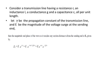
- The velocity at which waves travel depends on the line parameters of inductance and capacitance.
- Attenuation reduces the wave magnitude while distortion can change the wave shape as it moves along the line due to varying line properties.
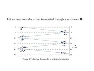
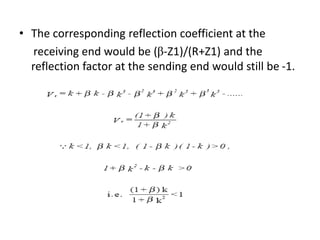
- Waves are partially reflected and transmitted at points where there are changes in the line, like at open circuits


![2.1 Velocity of Surge Propagation
• In the air = 300 000 km/s
• = 1/(LC) m/s
• Inductance single conductor Overhead Line (assuming zero
ground resistivity) :
L=2 x 10⁻⁷ ln (2h/r) H/m
C=1/[18 x 109 ln(2h/r)] F/m
•
• In the cable : = 1/(LC) = 3 x 10⁸ K m/s
K=dielectric constant (2.5 to 4.0)
1
2
/
1
9
7
/
2
ln
10
18
/
2
ln
10
2
1
r
h
r
h
LC
v](https://image.slidesharecdn.com/latticediagram-230810144005-5a12db3e/85/lattice-diagram-ppt-4-320.jpg)