Downloaded 3,589 times


![REFERENCES
[1] Lackner, M., Winter, F., What is ignition? Combustion File 256, IFRF Online Combustion Handbook, ISSN
1607-9116, International Flame Research Foundation, Ijmuiden, The Netherlands, (2004).
[2] H. Kopecek, M. Lackner, F. Winter, E. Wintner, Laser ignition of methane air mixtures at pressures up to 4 MPa,
Journal of Laser Physics 13 (11), 1365 (2003).
[3] Kopecek, H., Lackner, M., Wintner, E., Winter, F., Laser-Stimulated Ignition in a Homogeneous Charge Compression
Ignition Engine, SAE 2004 World Congress, paper No 2004-01-0937, Detroit, MI, USA (2004).
[4] J. D. Dale, M. D. Checkel, P. R. Smy, Application of High Energy Ignition Systems to Engines, Prog. Energy Combust.
Sci. 23, 379-398 (1997).
[5] Ronney P.D., Laser versus conventional ignition of flames, Optical Engineering 33(2),510 (1994).
[6] Phuoc T.X., White F.P., Laser-induced spark ignition of CH4/air mixtures, Combustion and Flame 119, 203-216
(1999).
[7] Radziemski L.J., Cremers D.A., Laser-induced plasmas and applications, New York-Basel: Marcel Dekker Inc.,
(1989).](https://image.slidesharecdn.com/j47mltyltemtrc3rbtww-signature-da04867ac08464fa4daa64491403a64959efcadf0639b4d34419fb9a82e1e2c2-poli-140906160343-phpapp01/85/LASER-Ignition-System-14-320.jpg)


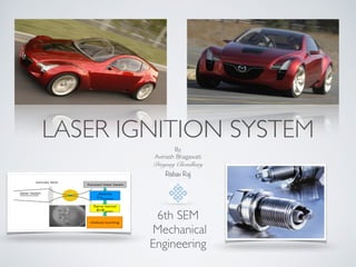
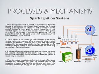
This document discusses the implementation of a laser ignition system (LIS) in internal combustion engines as an alternative to conventional spark plug ignition. It describes how LIS works through non-resonant breakdown to generate plasma and ignite fuel mixtures using a laser beam. LIS offers advantages like improved combustion efficiency from flexible ignition locations and ability to ignite leaner mixtures. While research has shown LIS can enable lower emissions and more stable combustion, its high cost remains a limitation.


