Downloaded 149 times
![PAAVAI COLLEGE OF ENGINEERING Seminar Report
17
CHAPTER -2
LITREATURE REVIEW
Takuma Endo & Keisuke Kuwamoto[1]
Et.al.in his study findings revealed that laser ignition was superior to
the spark-plug ignition in the aspect of the early- stage rapid flame spread, although
it showed lower probability of successful ignition than that by the spark plug near
the lean-fuel ignitable limit. These findings suggest that the ignition in high-speed
flows is significantly influenced by the turbulence via the enhancement of heat
transport in particular. investigated laser ignition to hydrogen–air mixtures at high
pressures and their results showed that with increasing initial pressures the minimum
pulse energy was decreasing. Measurements and model calculations of ignition by
electrical sparks and non resonant laser sparks show that the minimum ignition
energy (MIE) for laser sparks is higher than for electrical sparks
J. Griffiths, M.J.W. Rileyb & Borman[2]
Et.al.in his study developed an Extensive research into the application LI for
various applications such as internal combustion engines and natural gas
reciprocating engines has been conducted .The potential for the application of lasers
in the ignition process was first identified shortly after the advent of pulsed laser
sources in J. Griffiths 1964 by et al., who demonstrated breakdown of air using a
focused ruby laser .The LI process typically involves the use of tightly focused UV
to near-IR laser radiation to locally ionize target molecules in a combustible mixture,
leading to full-scale combustion. Laser ignition, microwave ignition, high frequency
ignition are among the concepts widely investigated.](https://image.slidesharecdn.com/santhoshauto-180419074932/85/Study-of-Laser-Ignition-System-LIS-Full-Report-17-320.jpg)
![PAAVAI COLLEGE OF ENGINEERING Seminar Report
18
J D Mullett , G Triantos, and S Keen[3]
Et.al.in his study was the Recent research in laser-induced ignition (LI) of
air–fuel mixtures in internal combustion (IC) engines has shown there to be many
potential advantages over conventional electrical spark ignition (SI) . Non-resonant
breakdown is the mechanism by which LI is performed in the tests presented in this
paper and is the most widely used and studied form of LI. Experimental studies have
been vital to extending the value of the theoretical examinations and in gaining a
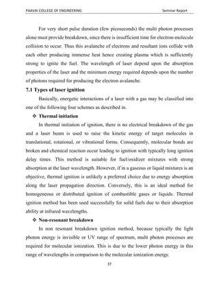
further understanding of the combustion process. Combustion vessel and open flame
jet experimentation with methane (CH4) and other combustible gases have proven
invaluable in the search for better fuel economy and emissions and provide a better
understanding of the general ignition and combustion processe
Cangsu Xu n, Donghua Fang& Jian Ma[4]
Et.al. in his study In recent years, laser ignition has become an active research
topic because of its many potential benefits over the conventional electric spark
ignition. Laser ignition of reactive mixtures can be divided into four categories: laser
thermal ignition, laser induced photochemical ignition, laser-induced resonant
breakdown ignition and laser induced spark ignition . Laser induced spark ignition
begins with the initial seed electrons produced from impurities in the gas mixture (e.
g dust, aerosol or soot particles). Experimental studies have been vital to extending
the value of the theoretical examinations and in gaining a further understanding of
the combustion process. Combustion vessel and open flame jet experimentation with
methane (CH4) and other combustible gases have proven invaluable in the search
for better fuel economy and emissions and provide a better understanding of the
general ignition and combustion process.](https://image.slidesharecdn.com/santhoshauto-180419074932/85/Study-of-Laser-Ignition-System-LIS-Full-Report-18-320.jpg)
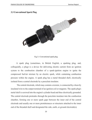
![PAAVAI COLLEGE OF ENGINEERING Seminar Report
19
Lydia Wermer a , James Hanssonb & Seong-kyun Im[5]
Et.al. in his study An experimental investigation was performed to study the
ignition and flame propagation behaviours of a methane diffusion jet flame (Re =
5500) when dual pulse laser-induced spark discharges were introduced in a mixing
layer. Initial electrons readily absorb more photons via the inverse bremsstrahlung
process to increase their kinetic energy. If the electrons gain sufficient energy, they
can collide with other molecules and ionize them, leading to an electron avalanche,
and breakdown the gas. This process is repeated until the spark plasma of high
temperature and high pressure is created. This extreme condition relative to the
ambient gas leads to the development of a rapidly expand- ing shock wave that is of
sufficient strength to ignite flammable mixtures.
J. D. Dale[6]
Et.al. in his study ,The use of laser ignition to improve gas engine performance
was initially demonstrated by J. D. Dale in 1978. However, with very few
exceptions, work in this area has for the last 20 years been limited to laboratory
experimentation employing large, expensive and relatively complicated lasers and
laser beam delivery systems. Experimental studies have been vital to extending the
value of the theoretical examinations and in gaining a further understanding of the
combustion process. Experimental studies have been vital to extending the value of
the theoretical examinations and in gaining a further understanding of the
combustion process. Combustion vessel and open flame jet experimentation with
methane (CH4) and other combustible gases have proven invaluable in the search
for better fuel economy and emissions and provide a better understanding of the
general ignition and combustion processes.](https://image.slidesharecdn.com/santhoshauto-180419074932/85/Study-of-Laser-Ignition-System-LIS-Full-Report-19-320.jpg)
![PAAVAI COLLEGE OF ENGINEERING Seminar Report
20
M. D. Checkel, P. R. Smy[7]
Et.al. in his study used a gasoline-fueled stoichiometric operating internal
combustion engine for testing. And studied characterisation of laser ignition in
hydrogen–air mixtures in a combustion bomb at initial pressure of 3 MPa and
temperature 323 K and the results are compared with the laser ignition ones. They
found that the rate of pressure rise inside the combustion chamber was higher when
the mixture was ignited by laser plasma compared with spark plug ignition. Laser
ignition studies performed on internal combustion engines have allowed researchers
to directly study the effect that laser induced ignition has on the operating and
emissions characteristics of an operating engine. Past and recent studies have
indicated a higher and quicker combustion pressure rise with laser ignition.
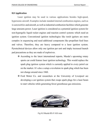
J. Ma, D. Alexander, and D. Poulain[8]
Et.al. in his study ,The research performed by Ma et al., involved a motored
slider crank mechanism that was not self sustaining.Researchers from Japan's
National Institutes of Natural Sciences (NINS) are creating laser igniters that could
one day replace spark plugs in automobile engines. The team from Japan built its
laser from two yttrium aluminum- gallium (YAG) segments, one doped with
neodymium, the other with chromium. They bonded the two sections together to
form a powerful laser only 9 millimeters in diameter and 11 millimeters long (a bit
less than half an inch). The composite generates two laser beams that can ignite fuel
in two separate locations at the same time. This would produce a flame wall that
grows faster and more uniformly than one lit by a single laser. The laser is not strong
enough to light the leanest fuel mixtures with a single pulse. By using several 800-
picosecond-long pulses, however, they can inject enough energy to ignite the
mixture completely](https://image.slidesharecdn.com/santhoshauto-180419074932/85/Study-of-Laser-Ignition-System-LIS-Full-Report-20-320.jpg)
![PAAVAI COLLEGE OF ENGINEERING Seminar Report
21
Kopecek, H., Lackner, M., Wintner, E., Winter[9]
Et.al. in his study This research is done to study the laser ignition of hydrogen
air mixture in a laser ignited internal combustion engine. In the research reported in
this paper, comparative study between conventional SI system and LI system were
carried out to investigate the technical potential of using LI system in a prototype
hydrogen fuelled engine. Engine performance, emission and combustion
characteristics for the two ignition systems are compared. So, many alternatives are
being sought after to counter these limitations. One of the alternative is the laser
ignition system (LIS) being described here. Compared to a conventional spark plug,
a LIS should be a favorable ignition source in terms of lean burn characteristics and
system flexibility . So, in this paper we'll be discussing the implementation and
impact of LIS on IC engines.
A.P. Yalin, M.W. Defoort, S. Joshi, D. Olsen, B. Willson, Y. Matsuura, M.
Miyagi[10]
Et.al. in his study This performed experiments to determine misfire limit and
knock limit of LI system. They reported increased misfire limit, and decreased
ignition delay for LI compared to SI engine. In the past, lasers that could meet those
requirements were limited to basic research because they were big, inefficient, and
unstable. Nor could they be located away from the engine, because their powerful
beams would destroy any optical fibers that delivered light to the cylinders. This
problem overcame by making composite lasers from ceramic powders. In this the
powders is heated and fuse into optically transparent solids and embeds metal ions
in them to tune their properties. Ceramics are easier to tune optically than
conventional crystals. They are also much stronger, more durable, and thermally
conductive, so they can dissipate the heat from an engine without breaking down.](https://image.slidesharecdn.com/santhoshauto-180419074932/85/Study-of-Laser-Ignition-System-LIS-Full-Report-21-320.jpg)


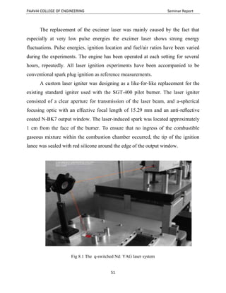

This seminar report presents a project on the study of laser ignition systems as an alternative to conventional spark plug ignition systems in internal combustion engines. The research highlights the advantages of laser ignition, including improved fuel combustion efficiency, reduced emissions, and better performance compared to spark plug systems. The report includes acknowledgments, an abstract, and detailed sections on literature review, methodology, and comparisons of ignition systems.


