SlideShare a Scribd company logo
1 of 12
PAAVAI COLLEGE OF ENGINEERING
PACHAL,NAMAKKAL
DEPARTMENT OF AUTOMOBILE ENGINEERING
Submitted by,
SANTHOSH KUMAR B
MOHAMMED JAKEER M
Laser ignition system
Abstract:
Nowadays, combustion engines and other combustion processes play an overwhelming and
important role in everyday life. As a result, study of ignition of combustion processes is of great
importance. In most cases, a well-defined ignition location and ignition time is crucial for an IC
engine. Spark plugs are well suited for such tasks but suffer from disadvantages, like erosion of
electrodes or restricted positioning possibilities. Over the conventional ignition systems, ignition
of combustible materials by means of high power laser pulses could be beneficial.
Due to market demands aimed at increasing the efficiency and the power density of IC
engines, existing ignition systems are rapidly approaching their limits. To avoid this, IC engine
manufacturers are seeking new technologies. The thermodynamic requirements of a high
compression ratio and ahigh power density are fulfilledwellby laserignition. Through this paper,
the objective is to present the current state of the relevant knowledge on fuel ignition and
discuss selected applications, advantages, in the context of combustion engines.
Sustainability with regard to internal combustion engines is strongly linked to the fuels burnt
and the overall efficiency. Laser ignition can enhance the combustion process and minimize
pollutant formation. This paper is on laser ignition of sustainable fuels for future internal
combustion engines. Ignition is the process of starting radical reactions until a self-sustaining
flame has developed. In technical appliances such as internal combustion engines, reliable
ignition is necessary for adequate systemperformance. Ignition strongly affects the formation of
pollutants and the extent of fuel conversion.
Laser ignition system can be a reliable way to achieve this. Fundamentally, there are four
different ways in which laser light can interact with a combustible mixture to initiate an ignition
event. They are referred to as
1. Thermal initiation,
2. Non resonant breakdown,
3. Resonant breakdown, and
4. Photochemical ignition.
By far the most commonly used technique is the non-resonant initiation of combustion
primarily because of its freedom in selecting the laser wavelength and ease of implementation.
Optical breakdown of a gas within the focal spot of a high power laser allows a very distinct
localization of the ignition spot in a combustible material. The hot plasma which forms during
this breakdown initiates the following self-propagating combustion process. At the end we have
discussed some experimental results regarding measurements of fuel consumption and
emissions which prove that laser ignition has important advantages compared to conventional
spark ignition systems. A major source of pollution was shown to be the internal combustion
engine (3) which produces principally carbon monoxide (CO), hydrocarbons (HC), nitric oxide
(NO), with small amounts of sulphur oxides (SO), lead (P b) and particulates. One source of
American data (4) quotes the contribution of the automobile to atmospheric pollution as high
as: CO 90 per cent, HC 65 per cent and NO, (nitrogen oxides) 60 per cent. Emissions are must
reducing by help of laser ignition system due to incomplete combustion.
Introduction :
In technical appliances such as internal combustion engines, reliable ignition is necessary for
adequate systemperformance. Economic as well as environmental constraints demand afurther
reduction in the fuel consumption and the exhaust emissions of motor vehicles. At the moment,
direct injected fuel engines show the highest potential in reducing fuel consumption and exhaust
emissions.
Unfortunately, conventional spark plug ignition shows a major disadvantage with modern
spray-guided combustion processes sincethe ignition location cannot be chosen optimally. From
the viewpoint of gas engine R&D engineers, ignition of the fuel/air mixture by means of a laser
has great potential. Especially the thermodynamic requirements of a high compression ratio and
a high power density are fulfilled well by laser ignition. Additionally, the spark plug electrodes
can influence the gas flow insidethe combustion chamber. Ignition strongly affects the formation
of pollutants and the extent of fuel conversion. Laser ignition system can be a reliable way to
achieve this.
Background Study of Ignition in IC Engine
What is ignition?
Ignition is the process of starting radical reactions until a self-sustaining flame has
developed. One can distinguish between auto ignition, induced ignition and photo-ignition, the
latter being caused by photolytic generation of radicals.
Ignition Types
A. Compression Ignition (CI) or Auto Ignition At certain values of temperature and pressure
a mixture will ignite spontaneously, this is known as the auto ignition or compression ignition.
B. Induced Ignition A process where a mixture, which would not ignite by it, is ignited locally
by an ignition source (i.e. Electric spark plug, pulsed laser, microwave ignition source) is called
induced ignition. In induced ignition, energy is deposited, leading to a temperature rise in a small
volume of the mixture, where auto ignition takes place or the energy is used for the generation
of radicals. In both cases subsequent flame propagation occurs and sets the mixture on fire.
Conventional Sparking Plug Ignition
Conventional spark plug ignition has been used for many years. For ignition of a fuel-air
mixture the fuel-air mixture is compressed and at the right moment a high voltage is applied to
the electrodes of the spark plug.
Alternative ignition systems
In technical appliances like automatic burners and internal combustion engines, the electric
spark plug has been in use for more than a century. For the ignition of especially fuel lean
mixtures, alternatives to conventional electric spark ignition systems have been devised: high-
energy spark plugs,plasmajet igniters, railplug igniters, torch jet igniters,and pulsed-jet igniters,
exhaust gas recirculation (EGR) ignition systems, laser-induced spark ignition and flame jet
igniters.
Drawbacks of Conventional Ignition System
• Location of spark plug is not flexible as it requires shielding of plug from immense heat
and `fuel spray
• Ignition location cannot be chosen optimally.
• Spark plug electrodes can disturb the gas flow within the combustion chamber.
• It is not possible to ignite inside the fuel spray.
• It requires frequent maintenance to remove carbon deposits.
• Leaner mixtures cannot be burned, ratio between fuel and air has to be within the correct
range.
• Degradation of electrodes at high pressure and temperature.
• Flame propagation is slow.
• Multi point fuel ignition is not feasible.
• Higher turbulence levels are required.
• Erosion of spark plug electrodes.
LASER
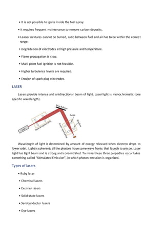
Lasers provide intense and unidirectional beam of light. Laser light is monochromatic (one
specific wavelength).
Wavelength of light is determined by amount of energy released when electron drops to
lower orbit. Light is coherent; allthe photons have same wave fronts that launch to unison. Laser
light has tight beam and is strong and concentrated. To make these three properties occur takes
something called “Stimulated Emission”, in which photon emission is organized.
Types of lasers
• Ruby laser
• Chemical lasers
• Excimer lasers
• Solid-state lasers
• Semiconductor lasers
• Dye lasers
Laser ignition
Laserignition, or laser-induced ignition, is the process of starting combustion by the stimulus
of a laser light source.
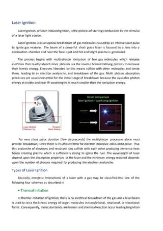
Laser ignition uses an optical breakdown of gas molecules caused by an intense laser pulse
to ignite gas mixtures. The beam of a powerful short pulse laser is focused by a lens into a
combustion chamber and near the focal spot and hot and bright plasma is generated.
The process begins with multi-photon ionization of few gas molecules which releases
electrons that readily absorb more photons via the inverse bremsstrahlung process to increase
their kinetic energy. Electrons liberated by this means collide with other molecules and ionize
them, leading to an electron avalanche, and breakdown of the gas. Multi photon absorption
processes are usually essential for the initial stage of breakdown because the available photon
energy at visible and near IR wavelengths is much smaller than the ionization energy.
For very short pulse duration (few picoseconds) the multiphoton processes alone must
provide breakdown, since there is insufficient time for electron-molecule collision to occur. Thus
this avalanche of electrons and resultant ions collide with each other producing immense heat
hence creating plasma which is sufficiently strong to ignite the fuel. The wavelength of laser
depend upon the absorption properties of the laser and the minimum energy required depends
upon the number of photons required for producing the electron avalanche.
Types of Laser Ignition
Basically, energetic interactions of a laser with a gas may be classified into one of the
following four schemes as described in
• Thermal initiation
In thermal initiation of ignition, there is no electrical breakdown of the gas and a laser beam
is used to raise the kinetic energy of target molecules in translational, rotational, or vibrational
forms. Consequently, molecular bonds are broken and chemicalreaction occur leading to ignition
with typically long ignition delay times. This method is suitable for fuel/oxidizer mixtures with
strong absorption at the laser wavelength. However, if in a gaseous or liquid mixtures is an
objective, thermal ignition is unlikely a preferred choice due to energy absorption along the laser
propagation direction. Conversely, this is an ideal method for homogeneous or distributed
ignition of combustible gases or liquids. Thermal ignition method has been used successfully for
solid fuels due to their absorption ability at infrared wavelengths.
• Non-resonant breakdown
In non resonant breakdown ignition method, because typically the light photon energy is
invisibleor UV range of The laserenergy is deposited in a few nanoseconds which lead to ashock
wave generation. In the first milliseconds an ignition delay can be observed which has duration
between 5 – 100 ms depending on the mixture. Combustion can last between 100 ms up to
several seconds again depending on the gas mixture, initial pressure, pulse energy, plasma size,
spectrum ,multiphoton processes are required for molecular
This is due to the lower photon energy in this range of wavelengths in comparison to the
molecular ionization energy. The electrons thus freed will absorb more energy to boost their
kinetic energy (KE), facilitating further molecular ionization through collision with other
molecules. This process shortly leads to an electron avalanche and ends with gas breakdown and
ignition. By far, the most commonly used technique is the non resonant initiation of ignition
primarily because of the freedom in selection of the laser wavelength and ease of
implementation.
• Resonant breakdown
The resonant breakdown laser ignition process involves, first, a non resonant multiphoton
dissociation of molecules resulting to freed atoms, followed by a resonant photo ionization of
these atoms. This process generates sufficient electrons needed for gas breakdown.
Theoretically, less input energy is required due to the resonant nature of this method.
• Photochemical mechanisms
In photochemical ignition approach, very little direct heating takes place and the laserbeam
brings about molecular dissociationleading to formation of radicals (i.e., highly reactive chemical
species), if the production rate of the radicals produced by this approach is higher than the
recombination rate (i.e.,neutralizing the radicals),then the number of these highly activespecies
will reach a threshold value, leading to an ignition event. This (radical) number augmentation
scenario is named as chain-branching in chemical terms.
• Laser Ignition process along time
Laser ignition encompasses the nanosecond domain of the laser pulse itself to the duration
of the entire combustion lasting several hundreds of milliseconds. position of the plasma in the
combustion bomb and initial temperature.
Experimental
This section describes the experimental setup. Laser ignition experiments were carried out
in a constant volume vessel (0.9 l) and an internal combustion engine.
The constant volume vessel, also termed the combustion bomb, was used to conduct basic
studies of laser ignition in homogeneous fuel/air mixtures. The sustainable fuels hydrogen and
biogas were used. The biogas was obtained from a municipal water purification plant. It was
composed of 50.5% CH4, 31.7% CO2 and 80 ppm H2S. Schlieren photography was used for
accompanying optical diagnostics.
The engine, a one-cylinder research engine, was deployed for the investigation of spray-
guided combustion initiated by a laser. Gasoline was used as a fuel here. The focus of
sustainability is on laser ignition for enhanced combustion and efficiency.
Laser ignition of biogas/air mixtures
Biogas isCO2-neutral and can act as a promisingalternative fuel havingahigh availability.The two
most commonsources of biogas are digestergasand landfill gas.Bacteriaform biogasduringanaerobic
fermentation of organic matters. The degradation is a very complex process and requires certain
environmental conditions.Biogasisprimarilycomposedof CH4(50-70%) andCO2 (25-50%). Digestergas
isproducedatsewage plantsduringtreatmentof municipalandindustrialsewage.Landfillgasisobtained
duringdecompositionof organicwaste insanitarylandfills.Whenusingbiogasasfuel one mustalsopay
attention to several harmful ingredients such as H2S polluting e.g. the catalytic converter of the engine
or blocking the window of the laser (see later for issues related to the window). With respect to laser
ignition, biogas was compared to methane.
The investigatedmethane/airandbiogas/airmixturescontainedsimilarmethaneconcentrationsbut
in the case of biogas additionally CO2 was present. Fuel-lean biogas/air mixtures exhibit a slower
combustion process resulting in lower peak pressure and flame emission compared to methane-air
mixturesof similarairtofuel equivalence ratio.The reasonfortheseresultscouldbe due tothe presence
of CO2 inthe biogaswhichreducesthe burningvelocitydue toobstructingthe flame propagationduring
combustion. SO2 may also be responsible for the decreased burning rate of the biogas/air mixtures
reducing mainly the O-radical concentration to equilibrium state due to the recombination of the O-
radicals images of the developing flame kernel in laser ignited biogas/air mixtures are depicted (see
below). More details on laser ignition of biogas/air mixtures can be found in.
Engine tests
Engine tests were conducted to investigate the optical window with respect to
• Durability of the optics (vibrations)
• Minimum ignition energy
• Wear and fouling properties of the inner window surface
The engine testswereconductedwithgasoline.Whereasthefocusof theprevioustestsandongoing
workina staticcombustionbombwasonthe understandingof the ignitionprocess,the aimof theengine
tests was to investigate the durability of the optical window.
Properties of the optical window
Potential window materialsevidentlyhave tobe transparentfor the laserradiation.The laser used
inthese testswasa Nd:YAG laserat 1064 nm.The nearinfraredspectral regionisacommonwavelength
regionforlasersuitableforlaserignitiontestruns.Soinfraredtransparentwindowsare goodcandidates
for a future laser ignition system. The second, no less important prerequisite is that the window
withstand the high energy density of the laser. The shorter the focal length of the lens, the higher
generally the laser light intensity of the passing laser beam becomes at the window surface. Third,the
windowmustshowaweakinclinationtodepositsandaidlaserself-cleaning. Combustionbombdeposits
can either be organic (up to 300°C) or inorganic in nature. When they form on the window, they
increasinglyblockthe incominglaserlightuptoa pointwhere nobreakdowncanbe producedanymore.
for instance,laserignitiontestsof methane/airmixturesinanengine hadto be abortedafter1.25 hours
because of excessivecombustionproductbuild-up.ZnSewasusedinthatstudy.The formationof deposits
on the window depends on the temperature, the fuel and the engine oil.
Optics deposits and self-cleaning effect
As statedabove,laserignitionisbasedonthe principle of optical breakdownandthusitis essential
to provide the necessaryintensitywhichisapproximately1011 W/cm2 in the focus.The energyemitted
from the laseris attenuatedbyreflectionsonthe surface of the window andthe lensand by absorption
inthe lens,inthe combustion-chamberwindowandinthe depositsonthe windows.The transmissionof
typical windowsinthe infraredis approximately90%;the reflectionsonthe surfacesfurtherreduce the
energy. Adding it up, when the laser beam passes through a window or a lens, the losses amount to
approximately15%.The laserself-cleaningeffectwasstudiedwithdepositsfromthe “true”combustion
process and also with artificially applied deposits .
Laser self-cleaning with deposits caused by the combustion process
Fig. 6 shows the cold start performance of the engine with a soiled window. Here, the deposits
stemmed from a real combustion process inside the engine. These deposits,which were caused by the
combustion process, were built up during the tests with a conventional spark plug. Thereby the
combustion-chamber window was installed in different load points, the engine running mode being
homogeneous, for about 20 hours. the window was soiledwith a dark and opaque layer of combustion
deposits after these 20 hours.
In the simulatedcold-starttestwithastratifiedenginerunningmode with 1000 rpm (rotationsper
minute) andPMEP=1bar, the PMEPcourse wasrecordedforeachcycle (MEP=meaneffectivepressure).
The first ignition and injection impulse occurred at cycle 10.
The first laser impulse already ignites the mixture. The following ignition impulses resulted in a
running without misfire. After the test (100 cycles) the window was dis assembled.all deposits were
removed in the beam passage area.
Laser self-cleaning with “worst case” deposits
In orderto studythe effectof the laserona heavilysoiledwindow,itwaschosentoartificially apply
a layer of dirt onto the window. This artificially applied soiling on the combustion-chamber side of the
window representsa kind of “worst case scenario”. For doing so, a mixture of Diesel sootand waste oil
at a ratioof 1:5 wasproducedand,with athicknessof 1mm, appliedtothe combustion-chamberwindow
and afterwardsdried. the clearinfluence of the laserenergyonthe self-cleaningeffectof the optics.Up
to a build-up energy of the threshold energy ES, an engine operation without misfire is possible witha
separated optics configuration, presupposed that a corresponding pulse number for the burning-off of
the windowisshot.Thisbuild-upenergyESissignificantlyhigherincombinedopticswhenaimingtoreach
a misfire rate of 0%. The relative laser energy was replaced by the actually occurring relative energy
intensity I on the combustion- chamber side of the window .
An engine operation without misfire with both optics configurations, i.e. separated and combined
optics,ispossible asof abuild-upintensityof IS.Inseparatedopticsthisbuild-upintensityIScorresponds
to the build-up energy of ES.
The minimum ignitionenergywhenthe engine running is stationaryis determinedby the intensity
level of self-cleaning at the optics, and not by the engine-relatedworking process. In the whole engine
operatingmap a secure ignitionandself-cleaningof the opticscan be guaranteedwiththe laserenergy
ES. For cold start applications, the laser energy should thus be raised momentarily in order to burn off
possible deposits at the optics.
laser energy for the different window configurations .Both the minimum ignition energy (left bar)
and the laserenergyfora 20 hour testrun (rightbar) are shown.As itcan be clearlyseen,the combined
optics are more favourable than the separated optics with respect to required laser energy. The energy
density at the window is a major criterion for the ablation of combustion bomb deposits. During cold
start, heating up and in the case of existing deposits only a high laser energy density can ensure the
ablationeffectatthe locationof the laser.The energydensityistherefore animportantdeterminanton
the reliabilityof a future laserignitionsystem.the energydensityisbyan order of magnitude higherfor
the separated optics than for the combined optics for the chosen configuration. The separated optics
scheme leadstoahigherenergydensityatthe window.Especiallyinthe case of coldstartor unexpected
deposits, this setup should be more reliable than the combined optics.
There isa trade-off betweenlowlaserenergyrequirements(combinedoptics) andsystemreliability
(separated optics). From an engine manufacturer’s point of view, system reliability comes first, which
translates into higher required laser energies and hence higher system costs.
Challenges
Deliveringthe beamthroughfreespace andchannellingitintothecombustionchamberthroughthe
optical plug achieved the best results – reducing the Coefficient of Variation, making combustion
smootherand more fuel- efficient.The teamwas particularly keento deliverthe beamvia optical fibre,
since thiswaslikelytobe lesssusceptible toenginevibrationandcouldfacilitateimprovedenginelayout.
They tried out a range of optical fibres, including silica and sapphire, and experimented with different
internal fibre structures, core sizes and beam coupling optics.
Deliveringthe beamviaoptical fibre provedtobe more difficultthanthe researchteamhadhoped.
The fibre didn’trespondwelltoenginevibration,whichincreasedthe divergenceof the outputbeamand
reduced the beam mode quality.Bending the fibre was also problematical and up to 20 per cent of the
beam energy was lost with small bend diameters, while tight bends caused the fibre to fail altogether
after a period. What’s more, the high density of laser energy can cause immediate or long term
degradation,leadingtolossof beamtransmission –andtherefore lossof ignition.Carefuldesignof laser
parameters, fibre coupling and choice of optical media is crucial to avoid this. These problems can be
Laser ignition system
• More intense spark
• Free choice of the ignition location within the combustion chamber
• Leaner fuel can burn effectively
• Laser ignition system could cope with a stratified charge.
• Flame propagation is relatively fast resulting in shorter combustion time
• Easier possibility of multipoint ignition
• NOx emission
Engineswouldproduce lessNOxif theyburntmoreairandlessfuel,buttheywouldrequirethe plugs
to produce higher- energy sparks in order to do so. Less NOx emission
Additional advantages of LI:
• Absence of quenching effects by the spark plug electrodes
• No erosion effects as in the case of the spark plugs => lifetime of a laser ignition
• System expected to be significantly longer than that of a spark plug
• High load/ignition pressures possible => increase in efficiency
• Precise ignition timing possible
• Exact regulation of the ignition energy deposited in the ignition plasma
• Easier possibility of multipoint ignition
• Shorter ignition delay time and shorter combustion time
Conclusion
1. Laser ignition system allows almost free choice of the ignition location within the combustion
chamber, even inside the fuel spray.
2. Significant reductions in fuel consumption as well as reductions of exhaust gases show the
potential of the laser ignition process.
3. Minimumignitionenergyismainlydeterminedbythe necessary“self-cleaning”mechanismatthe
beam entrance window from combustion deposits and not by engine- related parameters.
4. No differences of the laser ignition process could be found at different laser wavelengths.
5. Laser ignition is nonintrusive in nature; high energy can be rapidly deposited, has limitedheat
losses, and is capable of multipoint ignition of combustible charges.
6. More importantly, it shows better minimum ignition energy requirement than electric spark
systems with lean and rich fuel/air mixtures.
7. It possessespotentialsforcombustionenhancementandbetterimmunitytospurioussignalsthat
may accidentally trigger electric igniters.
8. Althoughthe laserwill needto fire more than 50 timesper secondto produce 3000 RPM, it will
require lesspowerthancurrent spark plugs.The laserscan alsoreflectback from inside the cylindersto
relayinformationbasedonfuel typeusedandthe level ofignition,enablingcarstoreadjustthe quantities
of air and fuel for optimum performance
9. At present, a laser ignition plug is very expensive compared to a standard electrical spark plug
ignitionsystemanditisnowhere nearreadyfordeployment.Butthe potential andadvantagescertainly
make the laser ignition more attractive in many practical applications.

More Related Content

What's hot

Laser ignition report
Laser ignition reportLaser ignition report
Laser ignition reportvikas_17
 
Laser Ignition for Internal Combustion Engines 3228
Laser Ignition for Internal Combustion Engines 3228Laser Ignition for Internal Combustion Engines 3228
Laser Ignition for Internal Combustion Engines 3228Abhishek Hingmire
 
Power steering seminar report pdf download
Power steering seminar report pdf downloadPower steering seminar report pdf download
Power steering seminar report pdf downloadkiran555555
 
POWER GENERATION BY SPEED BREAKER
POWER GENERATION BY SPEED BREAKERPOWER GENERATION BY SPEED BREAKER
POWER GENERATION BY SPEED BREAKERRITESH D. PATIL
 
green engine
green enginegreen engine
green engineyramkaran
 
Ceramic disc brakes
Ceramic disc brakesCeramic disc brakes
Ceramic disc brakesch durgarao
 
Dual Fuel Engine
Dual Fuel Engine Dual Fuel Engine
Dual Fuel Engine Hassan Raza
 
Hydrogen fuel cell seminar
Hydrogen fuel cell seminar Hydrogen fuel cell seminar
Hydrogen fuel cell seminar RiteshYadav134
 
Construction and working of a Stirling engine model
Construction and working of a Stirling engine modelConstruction and working of a Stirling engine model
Construction and working of a Stirling engine modelLakshi Nandan Borah
 
Presentationonliquidnitrogenvehicle 121202023158-phpapp02 (1)
Presentationonliquidnitrogenvehicle 121202023158-phpapp02 (1)Presentationonliquidnitrogenvehicle 121202023158-phpapp02 (1)
Presentationonliquidnitrogenvehicle 121202023158-phpapp02 (1)Waqqas Zia
 
Ppt of tursuperbocharger
Ppt of tursuperbochargerPpt of tursuperbocharger
Ppt of tursuperbochargerArvind Yadav
 

What's hot (20)

Laser ignition report
Laser ignition reportLaser ignition report
Laser ignition report
 
Laser Ignition for Internal Combustion Engines 3228
Laser Ignition for Internal Combustion Engines 3228Laser Ignition for Internal Combustion Engines 3228
Laser Ignition for Internal Combustion Engines 3228
 
LASER Ignition System
LASER Ignition SystemLASER Ignition System
LASER Ignition System
 
Laser ignition system
Laser ignition systemLaser ignition system
Laser ignition system
 
Green Engine PPT
Green Engine PPTGreen Engine PPT
Green Engine PPT
 
Lean Burn Engine
Lean Burn EngineLean Burn Engine
Lean Burn Engine
 
Green engine
Green engineGreen engine
Green engine
 
Six Stroke Engine PPT
Six Stroke Engine PPTSix Stroke Engine PPT
Six Stroke Engine PPT
 
Power steering seminar report pdf download
Power steering seminar report pdf downloadPower steering seminar report pdf download
Power steering seminar report pdf download
 
POWER GENERATION BY SPEED BREAKER
POWER GENERATION BY SPEED BREAKERPOWER GENERATION BY SPEED BREAKER
POWER GENERATION BY SPEED BREAKER
 
green engine
green enginegreen engine
green engine
 
Green engine 2015
Green engine 2015Green engine 2015
Green engine 2015
 
Nano ic engines
Nano ic enginesNano ic engines
Nano ic engines
 
Ceramic disc brakes
Ceramic disc brakesCeramic disc brakes
Ceramic disc brakes
 
Dual Fuel Engine
Dual Fuel Engine Dual Fuel Engine
Dual Fuel Engine
 
Hydrogen fuel cell seminar
Hydrogen fuel cell seminar Hydrogen fuel cell seminar
Hydrogen fuel cell seminar
 
Polution less engine
Polution less enginePolution less engine
Polution less engine
 
Construction and working of a Stirling engine model
Construction and working of a Stirling engine modelConstruction and working of a Stirling engine model
Construction and working of a Stirling engine model
 
Presentationonliquidnitrogenvehicle 121202023158-phpapp02 (1)
Presentationonliquidnitrogenvehicle 121202023158-phpapp02 (1)Presentationonliquidnitrogenvehicle 121202023158-phpapp02 (1)
Presentationonliquidnitrogenvehicle 121202023158-phpapp02 (1)
 
Ppt of tursuperbocharger
Ppt of tursuperbochargerPpt of tursuperbocharger
Ppt of tursuperbocharger
 

Viewers also liked

Report on laser ignition system
Report on laser ignition systemReport on laser ignition system
Report on laser ignition systemHimanshu Rajput
 
Laser Ignition System For IC Engine.
Laser Ignition System For IC Engine.Laser Ignition System For IC Engine.
Laser Ignition System For IC Engine.surajpdsss5
 
Laser ignition in IC Engines
Laser ignition in IC EnginesLaser ignition in IC Engines
Laser ignition in IC EnginesAnkush Wawoo
 
Laser ignition system technology
Laser ignition system technologyLaser ignition system technology
Laser ignition system technologyjignesh parmar
 
LASER INDUCED IGNITION FOR I C ENGINES
LASER INDUCED IGNITION FOR I C ENGINES LASER INDUCED IGNITION FOR I C ENGINES
LASER INDUCED IGNITION FOR I C ENGINES SUDHEESH SANKAR S R
 
Performance Study of Ethanol Blended Gasoline Fuel in Spark Ignition Engine
Performance Study of Ethanol Blended Gasoline Fuel in Spark Ignition EnginePerformance Study of Ethanol Blended Gasoline Fuel in Spark Ignition Engine
Performance Study of Ethanol Blended Gasoline Fuel in Spark Ignition EngineIOSR Journals
 
LPG Injection in Compression Ignition Engines
LPG Injection in Compression Ignition EnginesLPG Injection in Compression Ignition Engines
LPG Injection in Compression Ignition EnginesRob Harvey
 
Ilm shiatsu fræðin
Ilm shiatsu fræðinIlm shiatsu fræðin
Ilm shiatsu fræðinsigrunasgeirs
 
Blind spot detection with automatic steering
Blind spot detection with automatic steeringBlind spot detection with automatic steering
Blind spot detection with automatic steeringeSAT Journals
 

Viewers also liked (16)

Report on laser ignition system
Report on laser ignition systemReport on laser ignition system
Report on laser ignition system
 
Laser Ignition System For IC Engine.
Laser Ignition System For IC Engine.Laser Ignition System For IC Engine.
Laser Ignition System For IC Engine.
 
Laser ignition in IC Engines
Laser ignition in IC EnginesLaser ignition in IC Engines
Laser ignition in IC Engines
 
Laser ignition system technology
Laser ignition system technologyLaser ignition system technology
Laser ignition system technology
 
LASER INDUCED IGNITION FOR I C ENGINES
LASER INDUCED IGNITION FOR I C ENGINES LASER INDUCED IGNITION FOR I C ENGINES
LASER INDUCED IGNITION FOR I C ENGINES
 
Performance Study of Ethanol Blended Gasoline Fuel in Spark Ignition Engine
Performance Study of Ethanol Blended Gasoline Fuel in Spark Ignition EnginePerformance Study of Ethanol Blended Gasoline Fuel in Spark Ignition Engine
Performance Study of Ethanol Blended Gasoline Fuel in Spark Ignition Engine
 
LPG Injection in Compression Ignition Engines
LPG Injection in Compression Ignition EnginesLPG Injection in Compression Ignition Engines
LPG Injection in Compression Ignition Engines
 
Chinmay
ChinmayChinmay
Chinmay
 
Ilm shiatsu fræðin
Ilm shiatsu fræðinIlm shiatsu fræðin
Ilm shiatsu fræðin
 
green engine
green enginegreen engine
green engine
 
GREEN ENGINE 2
GREEN ENGINE 2GREEN ENGINE 2
GREEN ENGINE 2
 
Green engine
Green engineGreen engine
Green engine
 
Blind spot detection with automatic steering
Blind spot detection with automatic steeringBlind spot detection with automatic steering
Blind spot detection with automatic steering
 
SRW-Report
SRW-ReportSRW-Report
SRW-Report
 
Green engine
Green engineGreen engine
Green engine
 
Ankur green engine ppt
Ankur green engine pptAnkur green engine ppt
Ankur green engine ppt
 

Similar to Laser Ignition System (LIS)

Lazer ignition system
Lazer ignition systemLazer ignition system
Lazer ignition systemshubhambadhe5
 
laser-ignition-by-comburtion-engine.pdf
laser-ignition-by-comburtion-engine.pdflaser-ignition-by-comburtion-engine.pdf
laser-ignition-by-comburtion-engine.pdfSahilS39
 
laser ignition by comburtion engine
laser ignition by comburtion enginelaser ignition by comburtion engine
laser ignition by comburtion engineRamesh Biradar
 
A comparitive study of laser ignition and spark ignition with gasoline air m...
A comparitive study of laser  ignition and spark ignition with gasoline air m...A comparitive study of laser  ignition and spark ignition with gasoline air m...
A comparitive study of laser ignition and spark ignition with gasoline air m...Amiya K. Sahoo
 
Study of Laser Ignition System(LIS).ppt
Study of Laser Ignition System(LIS).pptStudy of Laser Ignition System(LIS).ppt
Study of Laser Ignition System(LIS).pptSanthosh Kumar B
 
Study of Laser Ignition System (ppt)
Study of Laser Ignition System (ppt)Study of Laser Ignition System (ppt)
Study of Laser Ignition System (ppt)Santhosh Kumar B
 
Study of laser ignition system.
Study of laser ignition system.Study of laser ignition system.
Study of laser ignition system.HarshitRuhela
 
Laser ignition for Internal Combustion Engines Nitish Sharma
Laser ignition for Internal Combustion Engines  Nitish SharmaLaser ignition for Internal Combustion Engines  Nitish Sharma
Laser ignition for Internal Combustion Engines Nitish SharmaNitish Sharma
 
LASER IGNITION SYSTEM PRESENTATION ASHUTOSH GAUR
LASER IGNITION SYSTEM PRESENTATION  ASHUTOSH GAURLASER IGNITION SYSTEM PRESENTATION  ASHUTOSH GAUR
LASER IGNITION SYSTEM PRESENTATION ASHUTOSH GAURSolidWorks Freelance
 
IRJET- Laser Ignition in Internal Combustion Engines – A Review
IRJET- Laser Ignition in Internal Combustion Engines – A ReviewIRJET- Laser Ignition in Internal Combustion Engines – A Review
IRJET- Laser Ignition in Internal Combustion Engines – A ReviewIRJET Journal
 
Atomic absorption spectroscopy (AAS).pptx
Atomic absorption spectroscopy (AAS).pptxAtomic absorption spectroscopy (AAS).pptx
Atomic absorption spectroscopy (AAS).pptxPriyankashah645680
 
Ice handout Spark ignition by Muhammad Zubair Qureshi
Ice handout Spark ignition by Muhammad Zubair QureshiIce handout Spark ignition by Muhammad Zubair Qureshi
Ice handout Spark ignition by Muhammad Zubair QureshiUET Lahore
 
Laser ignition for IC engines
Laser ignition for IC enginesLaser ignition for IC engines
Laser ignition for IC enginesVivekCholleti1
 
Flame emission spectroscopy and atomic absorption spectroscopy ppt
Flame emission spectroscopy and atomic absorption spectroscopy pptFlame emission spectroscopy and atomic absorption spectroscopy ppt
Flame emission spectroscopy and atomic absorption spectroscopy pptSachin G
 

Similar to Laser Ignition System (LIS) (20)

Tech seminar d v
Tech seminar d vTech seminar d v
Tech seminar d v
 
Lazer ignition system
Lazer ignition systemLazer ignition system
Lazer ignition system
 
laser-ignition-by-comburtion-engine.pdf
laser-ignition-by-comburtion-engine.pdflaser-ignition-by-comburtion-engine.pdf
laser-ignition-by-comburtion-engine.pdf
 
laser ignition by comburtion engine
laser ignition by comburtion enginelaser ignition by comburtion engine
laser ignition by comburtion engine
 
A comparitive study of laser ignition and spark ignition with gasoline air m...
A comparitive study of laser  ignition and spark ignition with gasoline air m...A comparitive study of laser  ignition and spark ignition with gasoline air m...
A comparitive study of laser ignition and spark ignition with gasoline air m...
 
Laser ignition system
Laser ignition systemLaser ignition system
Laser ignition system
 
Study of Laser Ignition System(LIS).ppt
Study of Laser Ignition System(LIS).pptStudy of Laser Ignition System(LIS).ppt
Study of Laser Ignition System(LIS).ppt
 
Study of Laser Ignition System (ppt)
Study of Laser Ignition System (ppt)Study of Laser Ignition System (ppt)
Study of Laser Ignition System (ppt)
 
Laser ignition for internal combustion engines
Laser ignition for internal combustion enginesLaser ignition for internal combustion engines
Laser ignition for internal combustion engines
 
Study of laser ignition system.
Study of laser ignition system.Study of laser ignition system.
Study of laser ignition system.
 
Laser ignition for Internal Combustion Engines Nitish Sharma
Laser ignition for Internal Combustion Engines  Nitish SharmaLaser ignition for Internal Combustion Engines  Nitish Sharma
Laser ignition for Internal Combustion Engines Nitish Sharma
 
LASER IGNITION SYSTEM PRESENTATION ASHUTOSH GAUR
LASER IGNITION SYSTEM PRESENTATION  ASHUTOSH GAURLASER IGNITION SYSTEM PRESENTATION  ASHUTOSH GAUR
LASER IGNITION SYSTEM PRESENTATION ASHUTOSH GAUR
 
Fuel energizer
Fuel energizerFuel energizer
Fuel energizer
 
IRJET- Laser Ignition in Internal Combustion Engines – A Review
IRJET- Laser Ignition in Internal Combustion Engines – A ReviewIRJET- Laser Ignition in Internal Combustion Engines – A Review
IRJET- Laser Ignition in Internal Combustion Engines – A Review
 
Atomic absorption spectroscopy (AAS).pptx
Atomic absorption spectroscopy (AAS).pptxAtomic absorption spectroscopy (AAS).pptx
Atomic absorption spectroscopy (AAS).pptx
 
Ice handout Spark ignition by Muhammad Zubair Qureshi
Ice handout Spark ignition by Muhammad Zubair QureshiIce handout Spark ignition by Muhammad Zubair Qureshi
Ice handout Spark ignition by Muhammad Zubair Qureshi
 
Fuel energizer
Fuel energizerFuel energizer
Fuel energizer
 
Laser ignition for IC engines
Laser ignition for IC enginesLaser ignition for IC engines
Laser ignition for IC engines
 
Seminar
SeminarSeminar
Seminar
 
Flame emission spectroscopy and atomic absorption spectroscopy ppt
Flame emission spectroscopy and atomic absorption spectroscopy pptFlame emission spectroscopy and atomic absorption spectroscopy ppt
Flame emission spectroscopy and atomic absorption spectroscopy ppt
 

Recently uploaded

Past, Present and Future of Generative AI
Past, Present and Future of Generative AIPast, Present and Future of Generative AI
Past, Present and Future of Generative AIabhishek36461
 
Study on Air-Water & Water-Water Heat Exchange in a Finned Tube Exchanger
Study on Air-Water & Water-Water Heat Exchange in a Finned Tube ExchangerStudy on Air-Water & Water-Water Heat Exchange in a Finned Tube Exchanger
Study on Air-Water & Water-Water Heat Exchange in a Finned Tube ExchangerAnamika Sarkar
 
Application of Residue Theorem to evaluate real integrations.pptx
Application of Residue Theorem to evaluate real integrations.pptxApplication of Residue Theorem to evaluate real integrations.pptx
Application of Residue Theorem to evaluate real integrations.pptx959SahilShah
 
DATA ANALYTICS PPT definition usage example
DATA ANALYTICS PPT definition usage exampleDATA ANALYTICS PPT definition usage example
DATA ANALYTICS PPT definition usage examplePragyanshuParadkar1
 
Call Girls Narol 7397865700 Independent Call Girls
Call Girls Narol 7397865700 Independent Call GirlsCall Girls Narol 7397865700 Independent Call Girls
Call Girls Narol 7397865700 Independent Call Girlsssuser7cb4ff
 
Introduction-To-Agricultural-Surveillance-Rover.pptx
Introduction-To-Agricultural-Surveillance-Rover.pptxIntroduction-To-Agricultural-Surveillance-Rover.pptx
Introduction-To-Agricultural-Surveillance-Rover.pptxk795866
 
Introduction to Machine Learning Unit-3 for II MECH
Introduction to Machine Learning Unit-3 for II MECHIntroduction to Machine Learning Unit-3 for II MECH
Introduction to Machine Learning Unit-3 for II MECHC Sai Kiran
 
Work Experience-Dalton Park.pptxfvvvvvvv
Work Experience-Dalton Park.pptxfvvvvvvvWork Experience-Dalton Park.pptxfvvvvvvv
Work Experience-Dalton Park.pptxfvvvvvvvLewisJB
 
INFLUENCE OF NANOSILICA ON THE PROPERTIES OF CONCRETE
INFLUENCE OF NANOSILICA ON THE PROPERTIES OF CONCRETEINFLUENCE OF NANOSILICA ON THE PROPERTIES OF CONCRETE
INFLUENCE OF NANOSILICA ON THE PROPERTIES OF CONCRETEroselinkalist12
 
GDSC ASEB Gen AI study jams presentation
GDSC ASEB Gen AI study jams presentationGDSC ASEB Gen AI study jams presentation
GDSC ASEB Gen AI study jams presentationGDSCAESB
 
pipeline in computer architecture design
pipeline in computer architecture  designpipeline in computer architecture  design
pipeline in computer architecture designssuser87fa0c1
 
Risk Assessment For Installation of Drainage Pipes.pdf
Risk Assessment For Installation of Drainage Pipes.pdfRisk Assessment For Installation of Drainage Pipes.pdf
Risk Assessment For Installation of Drainage Pipes.pdfROCENODodongVILLACER
 
What are the advantages and disadvantages of membrane structures.pptx
What are the advantages and disadvantages of membrane structures.pptxWhat are the advantages and disadvantages of membrane structures.pptx
What are the advantages and disadvantages of membrane structures.pptxwendy cai
 
UNIT III ANALOG ELECTRONICS (BASIC ELECTRONICS)
UNIT III ANALOG ELECTRONICS (BASIC ELECTRONICS)UNIT III ANALOG ELECTRONICS (BASIC ELECTRONICS)
UNIT III ANALOG ELECTRONICS (BASIC ELECTRONICS)Dr SOUNDIRARAJ N
 
Heart Disease Prediction using machine learning.pptx
Heart Disease Prediction using machine learning.pptxHeart Disease Prediction using machine learning.pptx
Heart Disease Prediction using machine learning.pptxPoojaBan
 
CCS355 Neural Network & Deep Learning Unit II Notes with Question bank .pdf
CCS355 Neural Network & Deep Learning Unit II Notes with Question bank .pdfCCS355 Neural Network & Deep Learning Unit II Notes with Question bank .pdf
CCS355 Neural Network & Deep Learning Unit II Notes with Question bank .pdfAsst.prof M.Gokilavani
 
Gfe Mayur Vihar Call Girls Service WhatsApp -> 9999965857 Available 24x7 ^ De...
Gfe Mayur Vihar Call Girls Service WhatsApp -> 9999965857 Available 24x7 ^ De...Gfe Mayur Vihar Call Girls Service WhatsApp -> 9999965857 Available 24x7 ^ De...
Gfe Mayur Vihar Call Girls Service WhatsApp -> 9999965857 Available 24x7 ^ De...srsj9000
 
Oxy acetylene welding presentation note.
Oxy acetylene welding presentation note.Oxy acetylene welding presentation note.
Oxy acetylene welding presentation note.eptoze12
 

Recently uploaded (20)

Past, Present and Future of Generative AI
Past, Present and Future of Generative AIPast, Present and Future of Generative AI
Past, Present and Future of Generative AI
 
Study on Air-Water & Water-Water Heat Exchange in a Finned Tube Exchanger
Study on Air-Water & Water-Water Heat Exchange in a Finned Tube ExchangerStudy on Air-Water & Water-Water Heat Exchange in a Finned Tube Exchanger
Study on Air-Water & Water-Water Heat Exchange in a Finned Tube Exchanger
 
Application of Residue Theorem to evaluate real integrations.pptx
Application of Residue Theorem to evaluate real integrations.pptxApplication of Residue Theorem to evaluate real integrations.pptx
Application of Residue Theorem to evaluate real integrations.pptx
 
DATA ANALYTICS PPT definition usage example
DATA ANALYTICS PPT definition usage exampleDATA ANALYTICS PPT definition usage example
DATA ANALYTICS PPT definition usage example
 
Call Girls Narol 7397865700 Independent Call Girls
Call Girls Narol 7397865700 Independent Call GirlsCall Girls Narol 7397865700 Independent Call Girls
Call Girls Narol 7397865700 Independent Call Girls
 
Call Us -/9953056974- Call Girls In Vikaspuri-/- Delhi NCR
Call Us -/9953056974- Call Girls In Vikaspuri-/- Delhi NCRCall Us -/9953056974- Call Girls In Vikaspuri-/- Delhi NCR
Call Us -/9953056974- Call Girls In Vikaspuri-/- Delhi NCR
 
young call girls in Green Park🔝 9953056974 🔝 escort Service
young call girls in Green Park🔝 9953056974 🔝 escort Serviceyoung call girls in Green Park🔝 9953056974 🔝 escort Service
young call girls in Green Park🔝 9953056974 🔝 escort Service
 
Introduction-To-Agricultural-Surveillance-Rover.pptx
Introduction-To-Agricultural-Surveillance-Rover.pptxIntroduction-To-Agricultural-Surveillance-Rover.pptx
Introduction-To-Agricultural-Surveillance-Rover.pptx
 
Introduction to Machine Learning Unit-3 for II MECH
Introduction to Machine Learning Unit-3 for II MECHIntroduction to Machine Learning Unit-3 for II MECH
Introduction to Machine Learning Unit-3 for II MECH
 
Work Experience-Dalton Park.pptxfvvvvvvv
Work Experience-Dalton Park.pptxfvvvvvvvWork Experience-Dalton Park.pptxfvvvvvvv
Work Experience-Dalton Park.pptxfvvvvvvv
 
INFLUENCE OF NANOSILICA ON THE PROPERTIES OF CONCRETE
INFLUENCE OF NANOSILICA ON THE PROPERTIES OF CONCRETEINFLUENCE OF NANOSILICA ON THE PROPERTIES OF CONCRETE
INFLUENCE OF NANOSILICA ON THE PROPERTIES OF CONCRETE
 
GDSC ASEB Gen AI study jams presentation
GDSC ASEB Gen AI study jams presentationGDSC ASEB Gen AI study jams presentation
GDSC ASEB Gen AI study jams presentation
 
pipeline in computer architecture design
pipeline in computer architecture  designpipeline in computer architecture  design
pipeline in computer architecture design
 
Risk Assessment For Installation of Drainage Pipes.pdf
Risk Assessment For Installation of Drainage Pipes.pdfRisk Assessment For Installation of Drainage Pipes.pdf
Risk Assessment For Installation of Drainage Pipes.pdf
 
What are the advantages and disadvantages of membrane structures.pptx
What are the advantages and disadvantages of membrane structures.pptxWhat are the advantages and disadvantages of membrane structures.pptx
What are the advantages and disadvantages of membrane structures.pptx
 
UNIT III ANALOG ELECTRONICS (BASIC ELECTRONICS)
UNIT III ANALOG ELECTRONICS (BASIC ELECTRONICS)UNIT III ANALOG ELECTRONICS (BASIC ELECTRONICS)
UNIT III ANALOG ELECTRONICS (BASIC ELECTRONICS)
 
Heart Disease Prediction using machine learning.pptx
Heart Disease Prediction using machine learning.pptxHeart Disease Prediction using machine learning.pptx
Heart Disease Prediction using machine learning.pptx
 
CCS355 Neural Network & Deep Learning Unit II Notes with Question bank .pdf
CCS355 Neural Network & Deep Learning Unit II Notes with Question bank .pdfCCS355 Neural Network & Deep Learning Unit II Notes with Question bank .pdf
CCS355 Neural Network & Deep Learning Unit II Notes with Question bank .pdf
 
Gfe Mayur Vihar Call Girls Service WhatsApp -> 9999965857 Available 24x7 ^ De...
Gfe Mayur Vihar Call Girls Service WhatsApp -> 9999965857 Available 24x7 ^ De...Gfe Mayur Vihar Call Girls Service WhatsApp -> 9999965857 Available 24x7 ^ De...
Gfe Mayur Vihar Call Girls Service WhatsApp -> 9999965857 Available 24x7 ^ De...
 
Oxy acetylene welding presentation note.
Oxy acetylene welding presentation note.Oxy acetylene welding presentation note.
Oxy acetylene welding presentation note.
 

Laser Ignition System (LIS)

  • 1. PAAVAI COLLEGE OF ENGINEERING PACHAL,NAMAKKAL DEPARTMENT OF AUTOMOBILE ENGINEERING Submitted by, SANTHOSH KUMAR B MOHAMMED JAKEER M
  • 2. Laser ignition system Abstract: Nowadays, combustion engines and other combustion processes play an overwhelming and important role in everyday life. As a result, study of ignition of combustion processes is of great importance. In most cases, a well-defined ignition location and ignition time is crucial for an IC engine. Spark plugs are well suited for such tasks but suffer from disadvantages, like erosion of electrodes or restricted positioning possibilities. Over the conventional ignition systems, ignition of combustible materials by means of high power laser pulses could be beneficial. Due to market demands aimed at increasing the efficiency and the power density of IC engines, existing ignition systems are rapidly approaching their limits. To avoid this, IC engine manufacturers are seeking new technologies. The thermodynamic requirements of a high compression ratio and ahigh power density are fulfilledwellby laserignition. Through this paper, the objective is to present the current state of the relevant knowledge on fuel ignition and discuss selected applications, advantages, in the context of combustion engines. Sustainability with regard to internal combustion engines is strongly linked to the fuels burnt and the overall efficiency. Laser ignition can enhance the combustion process and minimize pollutant formation. This paper is on laser ignition of sustainable fuels for future internal combustion engines. Ignition is the process of starting radical reactions until a self-sustaining flame has developed. In technical appliances such as internal combustion engines, reliable ignition is necessary for adequate systemperformance. Ignition strongly affects the formation of pollutants and the extent of fuel conversion. Laser ignition system can be a reliable way to achieve this. Fundamentally, there are four different ways in which laser light can interact with a combustible mixture to initiate an ignition event. They are referred to as 1. Thermal initiation, 2. Non resonant breakdown, 3. Resonant breakdown, and 4. Photochemical ignition. By far the most commonly used technique is the non-resonant initiation of combustion primarily because of its freedom in selecting the laser wavelength and ease of implementation. Optical breakdown of a gas within the focal spot of a high power laser allows a very distinct localization of the ignition spot in a combustible material. The hot plasma which forms during
  • 3. this breakdown initiates the following self-propagating combustion process. At the end we have discussed some experimental results regarding measurements of fuel consumption and emissions which prove that laser ignition has important advantages compared to conventional spark ignition systems. A major source of pollution was shown to be the internal combustion engine (3) which produces principally carbon monoxide (CO), hydrocarbons (HC), nitric oxide (NO), with small amounts of sulphur oxides (SO), lead (P b) and particulates. One source of American data (4) quotes the contribution of the automobile to atmospheric pollution as high as: CO 90 per cent, HC 65 per cent and NO, (nitrogen oxides) 60 per cent. Emissions are must reducing by help of laser ignition system due to incomplete combustion. Introduction : In technical appliances such as internal combustion engines, reliable ignition is necessary for adequate systemperformance. Economic as well as environmental constraints demand afurther reduction in the fuel consumption and the exhaust emissions of motor vehicles. At the moment, direct injected fuel engines show the highest potential in reducing fuel consumption and exhaust emissions. Unfortunately, conventional spark plug ignition shows a major disadvantage with modern spray-guided combustion processes sincethe ignition location cannot be chosen optimally. From the viewpoint of gas engine R&D engineers, ignition of the fuel/air mixture by means of a laser has great potential. Especially the thermodynamic requirements of a high compression ratio and a high power density are fulfilled well by laser ignition. Additionally, the spark plug electrodes can influence the gas flow insidethe combustion chamber. Ignition strongly affects the formation of pollutants and the extent of fuel conversion. Laser ignition system can be a reliable way to achieve this. Background Study of Ignition in IC Engine What is ignition? Ignition is the process of starting radical reactions until a self-sustaining flame has developed. One can distinguish between auto ignition, induced ignition and photo-ignition, the latter being caused by photolytic generation of radicals.
  • 4. Ignition Types A. Compression Ignition (CI) or Auto Ignition At certain values of temperature and pressure a mixture will ignite spontaneously, this is known as the auto ignition or compression ignition. B. Induced Ignition A process where a mixture, which would not ignite by it, is ignited locally by an ignition source (i.e. Electric spark plug, pulsed laser, microwave ignition source) is called induced ignition. In induced ignition, energy is deposited, leading to a temperature rise in a small volume of the mixture, where auto ignition takes place or the energy is used for the generation of radicals. In both cases subsequent flame propagation occurs and sets the mixture on fire. Conventional Sparking Plug Ignition Conventional spark plug ignition has been used for many years. For ignition of a fuel-air mixture the fuel-air mixture is compressed and at the right moment a high voltage is applied to the electrodes of the spark plug. Alternative ignition systems In technical appliances like automatic burners and internal combustion engines, the electric spark plug has been in use for more than a century. For the ignition of especially fuel lean mixtures, alternatives to conventional electric spark ignition systems have been devised: high- energy spark plugs,plasmajet igniters, railplug igniters, torch jet igniters,and pulsed-jet igniters, exhaust gas recirculation (EGR) ignition systems, laser-induced spark ignition and flame jet igniters. Drawbacks of Conventional Ignition System • Location of spark plug is not flexible as it requires shielding of plug from immense heat and `fuel spray • Ignition location cannot be chosen optimally. • Spark plug electrodes can disturb the gas flow within the combustion chamber.
  • 5. • It is not possible to ignite inside the fuel spray. • It requires frequent maintenance to remove carbon deposits. • Leaner mixtures cannot be burned, ratio between fuel and air has to be within the correct range. • Degradation of electrodes at high pressure and temperature. • Flame propagation is slow. • Multi point fuel ignition is not feasible. • Higher turbulence levels are required. • Erosion of spark plug electrodes. LASER Lasers provide intense and unidirectional beam of light. Laser light is monochromatic (one specific wavelength). Wavelength of light is determined by amount of energy released when electron drops to lower orbit. Light is coherent; allthe photons have same wave fronts that launch to unison. Laser light has tight beam and is strong and concentrated. To make these three properties occur takes something called “Stimulated Emission”, in which photon emission is organized. Types of lasers • Ruby laser • Chemical lasers • Excimer lasers • Solid-state lasers • Semiconductor lasers • Dye lasers
  • 6. Laser ignition Laserignition, or laser-induced ignition, is the process of starting combustion by the stimulus of a laser light source. Laser ignition uses an optical breakdown of gas molecules caused by an intense laser pulse to ignite gas mixtures. The beam of a powerful short pulse laser is focused by a lens into a combustion chamber and near the focal spot and hot and bright plasma is generated. The process begins with multi-photon ionization of few gas molecules which releases electrons that readily absorb more photons via the inverse bremsstrahlung process to increase their kinetic energy. Electrons liberated by this means collide with other molecules and ionize them, leading to an electron avalanche, and breakdown of the gas. Multi photon absorption processes are usually essential for the initial stage of breakdown because the available photon energy at visible and near IR wavelengths is much smaller than the ionization energy. For very short pulse duration (few picoseconds) the multiphoton processes alone must provide breakdown, since there is insufficient time for electron-molecule collision to occur. Thus this avalanche of electrons and resultant ions collide with each other producing immense heat hence creating plasma which is sufficiently strong to ignite the fuel. The wavelength of laser depend upon the absorption properties of the laser and the minimum energy required depends upon the number of photons required for producing the electron avalanche. Types of Laser Ignition Basically, energetic interactions of a laser with a gas may be classified into one of the following four schemes as described in • Thermal initiation In thermal initiation of ignition, there is no electrical breakdown of the gas and a laser beam is used to raise the kinetic energy of target molecules in translational, rotational, or vibrational forms. Consequently, molecular bonds are broken and chemicalreaction occur leading to ignition
  • 7. with typically long ignition delay times. This method is suitable for fuel/oxidizer mixtures with strong absorption at the laser wavelength. However, if in a gaseous or liquid mixtures is an objective, thermal ignition is unlikely a preferred choice due to energy absorption along the laser propagation direction. Conversely, this is an ideal method for homogeneous or distributed ignition of combustible gases or liquids. Thermal ignition method has been used successfully for solid fuels due to their absorption ability at infrared wavelengths. • Non-resonant breakdown In non resonant breakdown ignition method, because typically the light photon energy is invisibleor UV range of The laserenergy is deposited in a few nanoseconds which lead to ashock wave generation. In the first milliseconds an ignition delay can be observed which has duration between 5 – 100 ms depending on the mixture. Combustion can last between 100 ms up to several seconds again depending on the gas mixture, initial pressure, pulse energy, plasma size, spectrum ,multiphoton processes are required for molecular This is due to the lower photon energy in this range of wavelengths in comparison to the molecular ionization energy. The electrons thus freed will absorb more energy to boost their kinetic energy (KE), facilitating further molecular ionization through collision with other molecules. This process shortly leads to an electron avalanche and ends with gas breakdown and ignition. By far, the most commonly used technique is the non resonant initiation of ignition primarily because of the freedom in selection of the laser wavelength and ease of implementation. • Resonant breakdown The resonant breakdown laser ignition process involves, first, a non resonant multiphoton dissociation of molecules resulting to freed atoms, followed by a resonant photo ionization of these atoms. This process generates sufficient electrons needed for gas breakdown. Theoretically, less input energy is required due to the resonant nature of this method. • Photochemical mechanisms In photochemical ignition approach, very little direct heating takes place and the laserbeam brings about molecular dissociationleading to formation of radicals (i.e., highly reactive chemical species), if the production rate of the radicals produced by this approach is higher than the recombination rate (i.e.,neutralizing the radicals),then the number of these highly activespecies will reach a threshold value, leading to an ignition event. This (radical) number augmentation scenario is named as chain-branching in chemical terms.
  • 8. • Laser Ignition process along time Laser ignition encompasses the nanosecond domain of the laser pulse itself to the duration of the entire combustion lasting several hundreds of milliseconds. position of the plasma in the combustion bomb and initial temperature. Experimental This section describes the experimental setup. Laser ignition experiments were carried out in a constant volume vessel (0.9 l) and an internal combustion engine. The constant volume vessel, also termed the combustion bomb, was used to conduct basic studies of laser ignition in homogeneous fuel/air mixtures. The sustainable fuels hydrogen and biogas were used. The biogas was obtained from a municipal water purification plant. It was composed of 50.5% CH4, 31.7% CO2 and 80 ppm H2S. Schlieren photography was used for accompanying optical diagnostics. The engine, a one-cylinder research engine, was deployed for the investigation of spray- guided combustion initiated by a laser. Gasoline was used as a fuel here. The focus of sustainability is on laser ignition for enhanced combustion and efficiency. Laser ignition of biogas/air mixtures Biogas isCO2-neutral and can act as a promisingalternative fuel havingahigh availability.The two most commonsources of biogas are digestergasand landfill gas.Bacteriaform biogasduringanaerobic fermentation of organic matters. The degradation is a very complex process and requires certain environmental conditions.Biogasisprimarilycomposedof CH4(50-70%) andCO2 (25-50%). Digestergas isproducedatsewage plantsduringtreatmentof municipalandindustrialsewage.Landfillgasisobtained duringdecompositionof organicwaste insanitarylandfills.Whenusingbiogasasfuel one mustalsopay attention to several harmful ingredients such as H2S polluting e.g. the catalytic converter of the engine or blocking the window of the laser (see later for issues related to the window). With respect to laser ignition, biogas was compared to methane. The investigatedmethane/airandbiogas/airmixturescontainedsimilarmethaneconcentrationsbut in the case of biogas additionally CO2 was present. Fuel-lean biogas/air mixtures exhibit a slower combustion process resulting in lower peak pressure and flame emission compared to methane-air mixturesof similarairtofuel equivalence ratio.The reasonfortheseresultscouldbe due tothe presence of CO2 inthe biogaswhichreducesthe burningvelocitydue toobstructingthe flame propagationduring combustion. SO2 may also be responsible for the decreased burning rate of the biogas/air mixtures reducing mainly the O-radical concentration to equilibrium state due to the recombination of the O- radicals images of the developing flame kernel in laser ignited biogas/air mixtures are depicted (see below). More details on laser ignition of biogas/air mixtures can be found in. Engine tests Engine tests were conducted to investigate the optical window with respect to
  • 9. • Durability of the optics (vibrations) • Minimum ignition energy • Wear and fouling properties of the inner window surface The engine testswereconductedwithgasoline.Whereasthefocusof theprevioustestsandongoing workina staticcombustionbombwasonthe understandingof the ignitionprocess,the aimof theengine tests was to investigate the durability of the optical window. Properties of the optical window Potential window materialsevidentlyhave tobe transparentfor the laserradiation.The laser used inthese testswasa Nd:YAG laserat 1064 nm.The nearinfraredspectral regionisacommonwavelength regionforlasersuitableforlaserignitiontestruns.Soinfraredtransparentwindowsare goodcandidates for a future laser ignition system. The second, no less important prerequisite is that the window withstand the high energy density of the laser. The shorter the focal length of the lens, the higher generally the laser light intensity of the passing laser beam becomes at the window surface. Third,the windowmustshowaweakinclinationtodepositsandaidlaserself-cleaning. Combustionbombdeposits can either be organic (up to 300°C) or inorganic in nature. When they form on the window, they increasinglyblockthe incominglaserlightuptoa pointwhere nobreakdowncanbe producedanymore. for instance,laserignitiontestsof methane/airmixturesinanengine hadto be abortedafter1.25 hours because of excessivecombustionproductbuild-up.ZnSewasusedinthatstudy.The formationof deposits on the window depends on the temperature, the fuel and the engine oil. Optics deposits and self-cleaning effect As statedabove,laserignitionisbasedonthe principle of optical breakdownandthusitis essential to provide the necessaryintensitywhichisapproximately1011 W/cm2 in the focus.The energyemitted from the laseris attenuatedbyreflectionsonthe surface of the window andthe lensand by absorption inthe lens,inthe combustion-chamberwindowandinthe depositsonthe windows.The transmissionof typical windowsinthe infraredis approximately90%;the reflectionsonthe surfacesfurtherreduce the energy. Adding it up, when the laser beam passes through a window or a lens, the losses amount to approximately15%.The laserself-cleaningeffectwasstudiedwithdepositsfromthe “true”combustion process and also with artificially applied deposits . Laser self-cleaning with deposits caused by the combustion process Fig. 6 shows the cold start performance of the engine with a soiled window. Here, the deposits stemmed from a real combustion process inside the engine. These deposits,which were caused by the combustion process, were built up during the tests with a conventional spark plug. Thereby the combustion-chamber window was installed in different load points, the engine running mode being homogeneous, for about 20 hours. the window was soiledwith a dark and opaque layer of combustion deposits after these 20 hours.
  • 10. In the simulatedcold-starttestwithastratifiedenginerunningmode with 1000 rpm (rotationsper minute) andPMEP=1bar, the PMEPcourse wasrecordedforeachcycle (MEP=meaneffectivepressure). The first ignition and injection impulse occurred at cycle 10. The first laser impulse already ignites the mixture. The following ignition impulses resulted in a running without misfire. After the test (100 cycles) the window was dis assembled.all deposits were removed in the beam passage area. Laser self-cleaning with “worst case” deposits In orderto studythe effectof the laserona heavilysoiledwindow,itwaschosentoartificially apply a layer of dirt onto the window. This artificially applied soiling on the combustion-chamber side of the window representsa kind of “worst case scenario”. For doing so, a mixture of Diesel sootand waste oil at a ratioof 1:5 wasproducedand,with athicknessof 1mm, appliedtothe combustion-chamberwindow and afterwardsdried. the clearinfluence of the laserenergyonthe self-cleaningeffectof the optics.Up to a build-up energy of the threshold energy ES, an engine operation without misfire is possible witha separated optics configuration, presupposed that a corresponding pulse number for the burning-off of the windowisshot.Thisbuild-upenergyESissignificantlyhigherincombinedopticswhenaimingtoreach a misfire rate of 0%. The relative laser energy was replaced by the actually occurring relative energy intensity I on the combustion- chamber side of the window . An engine operation without misfire with both optics configurations, i.e. separated and combined optics,ispossible asof abuild-upintensityof IS.Inseparatedopticsthisbuild-upintensityIScorresponds to the build-up energy of ES. The minimum ignitionenergywhenthe engine running is stationaryis determinedby the intensity level of self-cleaning at the optics, and not by the engine-relatedworking process. In the whole engine operatingmap a secure ignitionandself-cleaningof the opticscan be guaranteedwiththe laserenergy ES. For cold start applications, the laser energy should thus be raised momentarily in order to burn off possible deposits at the optics. laser energy for the different window configurations .Both the minimum ignition energy (left bar) and the laserenergyfora 20 hour testrun (rightbar) are shown.As itcan be clearlyseen,the combined optics are more favourable than the separated optics with respect to required laser energy. The energy density at the window is a major criterion for the ablation of combustion bomb deposits. During cold start, heating up and in the case of existing deposits only a high laser energy density can ensure the ablationeffectatthe locationof the laser.The energydensityistherefore animportantdeterminanton the reliabilityof a future laserignitionsystem.the energydensityisbyan order of magnitude higherfor the separated optics than for the combined optics for the chosen configuration. The separated optics scheme leadstoahigherenergydensityatthe window.Especiallyinthe case of coldstartor unexpected deposits, this setup should be more reliable than the combined optics. There isa trade-off betweenlowlaserenergyrequirements(combinedoptics) andsystemreliability (separated optics). From an engine manufacturer’s point of view, system reliability comes first, which translates into higher required laser energies and hence higher system costs.
  • 11. Challenges Deliveringthe beamthroughfreespace andchannellingitintothecombustionchamberthroughthe optical plug achieved the best results – reducing the Coefficient of Variation, making combustion smootherand more fuel- efficient.The teamwas particularly keento deliverthe beamvia optical fibre, since thiswaslikelytobe lesssusceptible toenginevibrationandcouldfacilitateimprovedenginelayout. They tried out a range of optical fibres, including silica and sapphire, and experimented with different internal fibre structures, core sizes and beam coupling optics. Deliveringthe beamviaoptical fibre provedtobe more difficultthanthe researchteamhadhoped. The fibre didn’trespondwelltoenginevibration,whichincreasedthe divergenceof the outputbeamand reduced the beam mode quality.Bending the fibre was also problematical and up to 20 per cent of the beam energy was lost with small bend diameters, while tight bends caused the fibre to fail altogether after a period. What’s more, the high density of laser energy can cause immediate or long term degradation,leadingtolossof beamtransmission –andtherefore lossof ignition.Carefuldesignof laser parameters, fibre coupling and choice of optical media is crucial to avoid this. These problems can be Laser ignition system • More intense spark • Free choice of the ignition location within the combustion chamber • Leaner fuel can burn effectively • Laser ignition system could cope with a stratified charge. • Flame propagation is relatively fast resulting in shorter combustion time • Easier possibility of multipoint ignition • NOx emission Engineswouldproduce lessNOxif theyburntmoreairandlessfuel,buttheywouldrequirethe plugs to produce higher- energy sparks in order to do so. Less NOx emission Additional advantages of LI: • Absence of quenching effects by the spark plug electrodes • No erosion effects as in the case of the spark plugs => lifetime of a laser ignition • System expected to be significantly longer than that of a spark plug • High load/ignition pressures possible => increase in efficiency • Precise ignition timing possible • Exact regulation of the ignition energy deposited in the ignition plasma • Easier possibility of multipoint ignition
  • 12. • Shorter ignition delay time and shorter combustion time Conclusion 1. Laser ignition system allows almost free choice of the ignition location within the combustion chamber, even inside the fuel spray. 2. Significant reductions in fuel consumption as well as reductions of exhaust gases show the potential of the laser ignition process. 3. Minimumignitionenergyismainlydeterminedbythe necessary“self-cleaning”mechanismatthe beam entrance window from combustion deposits and not by engine- related parameters. 4. No differences of the laser ignition process could be found at different laser wavelengths. 5. Laser ignition is nonintrusive in nature; high energy can be rapidly deposited, has limitedheat losses, and is capable of multipoint ignition of combustible charges. 6. More importantly, it shows better minimum ignition energy requirement than electric spark systems with lean and rich fuel/air mixtures. 7. It possessespotentialsforcombustionenhancementandbetterimmunitytospurioussignalsthat may accidentally trigger electric igniters. 8. Althoughthe laserwill needto fire more than 50 timesper secondto produce 3000 RPM, it will require lesspowerthancurrent spark plugs.The laserscan alsoreflectback from inside the cylindersto relayinformationbasedonfuel typeusedandthe level ofignition,enablingcarstoreadjustthe quantities of air and fuel for optimum performance 9. At present, a laser ignition plug is very expensive compared to a standard electrical spark plug ignitionsystemanditisnowhere nearreadyfordeployment.Butthe potential andadvantagescertainly make the laser ignition more attractive in many practical applications.