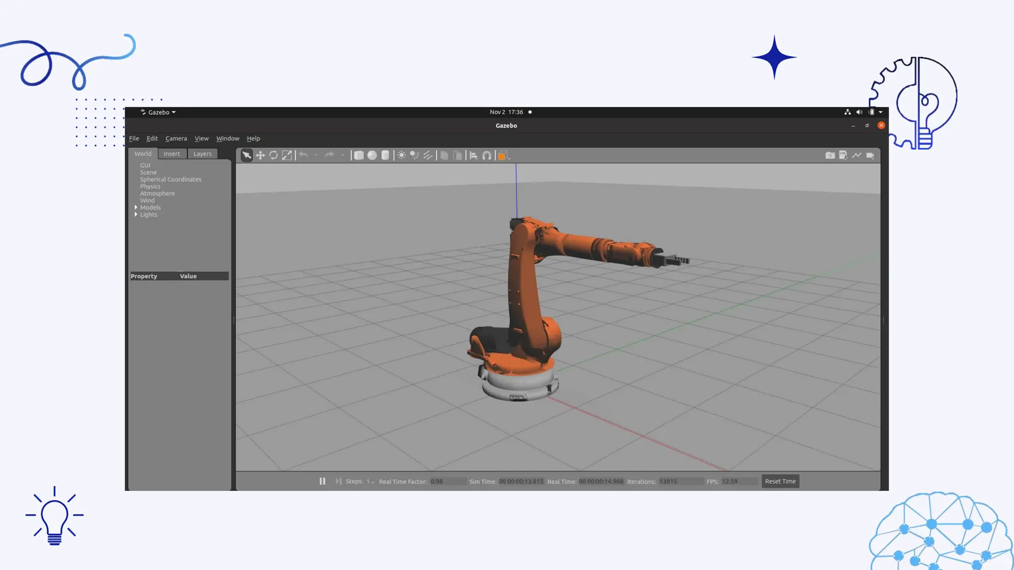
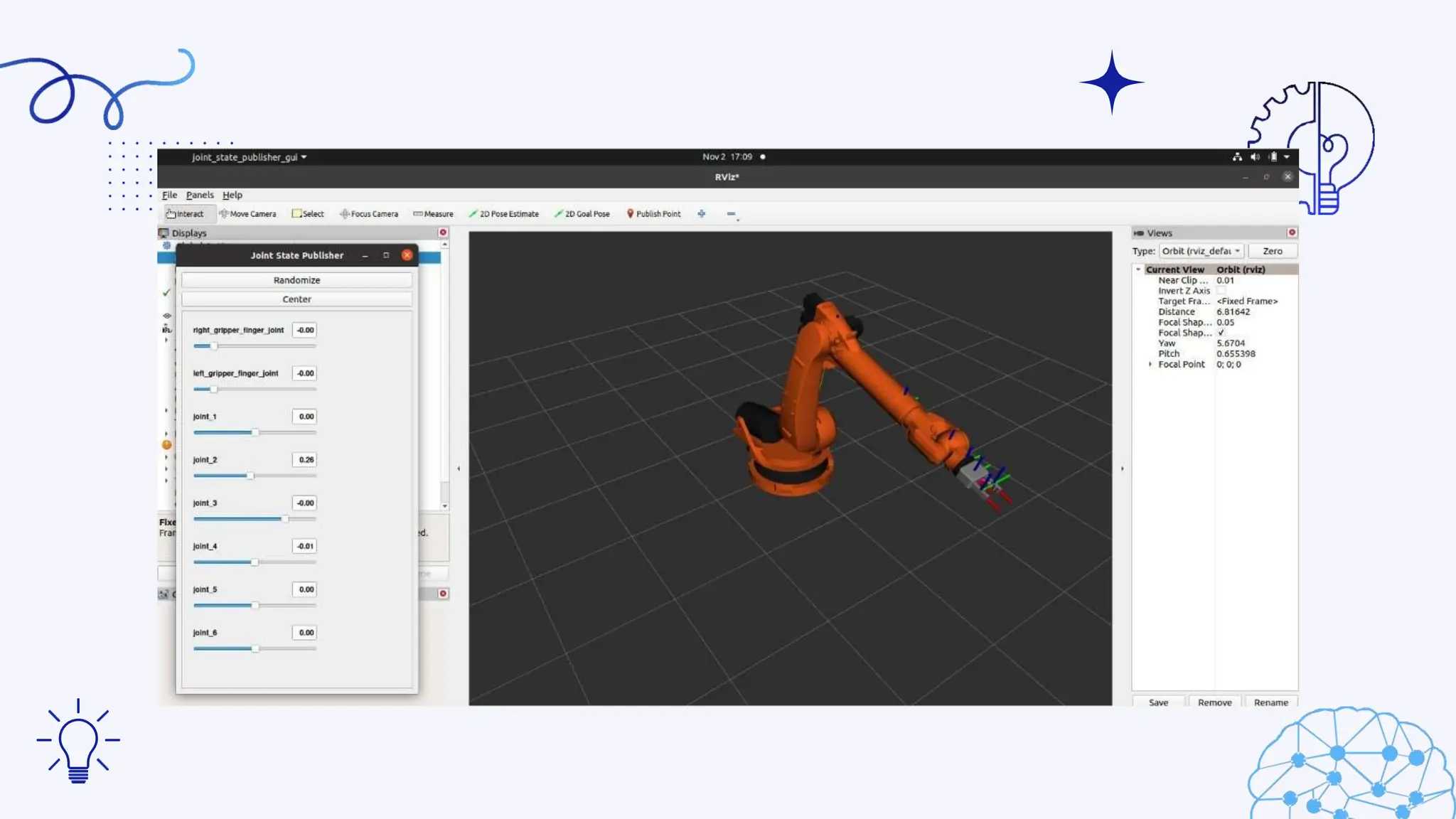
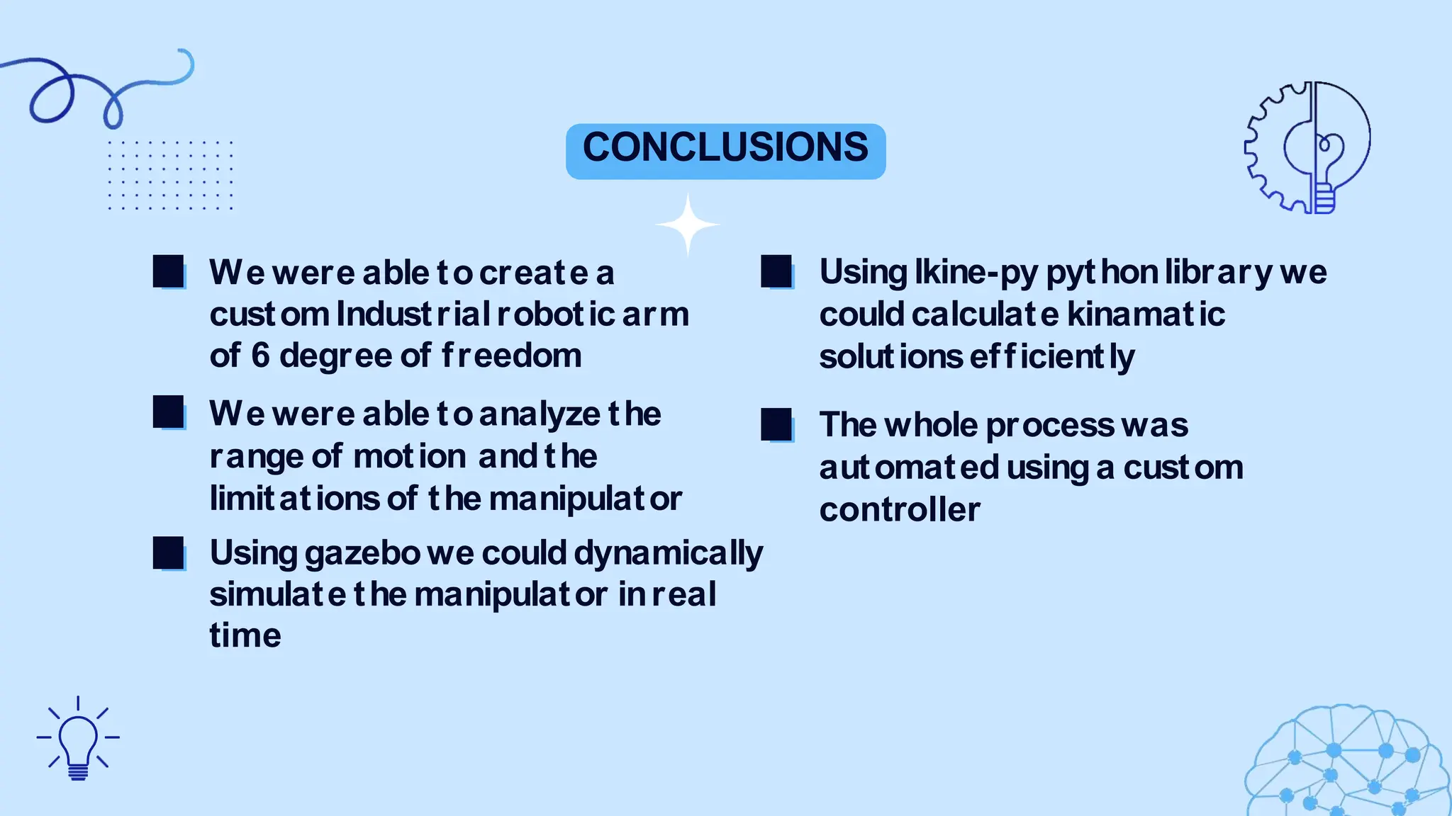
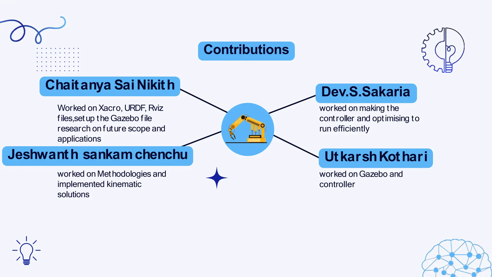
KUKAROBOT
CONTROL USING ROS2
BY
1.CHAITANYASAI NIKITH
2. DEV.S.SAKARIA
3. UTKARSHKOTHARI
4.JESHWANTHSANKAM CHENCHU
With the development and advancement of technologies inrobotics
and automation, the need for robots isbecomingmore prevalent.
Andthe robotic armis a type of mechanicalarmusually
programmable with similar functions to a humanarm, the linkof
such a manipulator is connected by joints allowing either rotational
or translation displacement. we willbe simulating the industrial
robotic arm manufactured anddeveloped by KUKAROBOTICS – KR
21
0 analyzing its path,range of motion,anddegrees of freedom.
ThisGerman-made manipulator isvery flexible dueto its shorter
cycle times and highquality also due to its lesser space
requirements compared to most industry standard robots, it is
very ergonomic and easy to implementinprocess planning.
Introductiontorobotic manipulators
Use of kinematic equations to determine the motion of the
robotic arm in each desired position. and the motion of the
manipulator iscalculated usingthe DH(Denavit -Hartenberg)
table and its associated parameters .Joint Trajectory
Controller wasusedtocontrolthe manipulator
Objective of our projrct
InterfacingKUKArobot
withROS2
SettingupKUKArobot
inGazebo
01
02
03
04
Creatinganeffective
controller for theRobot
Automationof the
KUKA KR-210
commercialapplications
commonusesof robotic arm
pickandplace
operations
machiningoperations
assembly operations
manipulator ina real-time environment. Theeffects of
gravity andinertia onthe manipulator helpedto
understand its workingto a greater extent. It helpedto
formulate the parameters of the controller whichis used
to controlthe manipulator.
Methodology
URDFFile
Xacrofiles cannot be readand
interpretedby simulating software
like RvizandGazebo,therefore they
have tobe changedinto a common
urdf file.Todothis the xacro
package is downloadedandused.
given
RVIZSETUP
Rvizis usedtocheckthe placement and
integration of all the joints present inthe
manipulator witheachother andalsowith
the base link.This setuphelpedus to
understand the movement of the
manipulator whendifferent values are
GAZEBO SIMULATION
The Gazeboenvironment helpedus to analyze the
We use the Joint Trajectory Controller to control the
manipulator.The robot state publisheris then called which tells us
the position of the manipulator. Thecontroller manager is then
communicated between the nodeand the controller isinitialised.An
action-client ismade to movethe manipulator ina specified path.
Thevalues of the points to be reached are pre-determined andare
calculatedbefore the controller is launched
Methodology
vectors.
FORWARD KINEMATICS
Forward kinematics uses joint angles to derive the
positionandorientationof the endeffector
(gripper) of the manipulator after it moves.It
requires linear algebra to calculate and manipulate
homogeneoustransformation matrices, whichare a
combinationof rotation matrices and displacement
INVERSEKINEMATICS
The‘Ikine-py’library also calculates the inverse
kinematic values for the manipulator with
respect to the jointspace of the environment. It
takes the values fromthe transformation
matrix and then calculates the orientation and
coordinates of the endeffector accordingly
CONTROLLER
RESULTS
TheKUKA-KR210manipulator has a maximumreach of 3100mmwhichwas
achieved whenthe coordinates for (x,y,z)where as follows(3.3,0.05,0.66).
Whenthe manipulator was stretcheduptothe maximum
extent its coordinates were as follows(0.47,0.0,3.78).
·
Tocheckthe grab height of the
manipulator it was programmed with
the coordinates (2.1
,0.0,1
.94).
·Theclaws of the gripper are controlled with
specific arugments ‘-c’for closing the claws and
‘-o’for openingthe gripper claws.
CONCLUSIONS
Usinglkine-py pythonlibrary we
couldcalculate kinamatic
solutionsefficiently
The whole processwas
automatedusinga custom
controller
We were able tocreate a
customIndustrialrobotic arm
of 6 degree of freedom
We were able toanalyze the
range of motion andthe
limitationsof the manipulator
Usinggazebowe coulddynamically
simulate the manipulator inreal
time
Contributions
Chaitanya SaiNikith
Worked on Xacro, URDF, Rviz
files,setup the Gazebo file
research on future scope and
applications
Jeshwanth sankamchenchu
worked on Methodologies and
implemented kinematic
solutions
Dev.S.Sakaria
worked on making the
controller and optimising to
run efficiently
UtkarshKothari
worked on Gazebo and
controller
References
[1] Ore, F.,Vemula, B.,Hanson,L.,Wiktorsson, M., & Fagerström, B.(2019). Simulation
methodology for performance and safety evaluation of human–industrial robot collaboration
workstation design. International Journal of Intelligent Robotics and Applications, 3(3), 269-282.
[2] Koivo, A.J., Fundamentals for Control of Robotic Manipulators, pp. 306-338, John
Wiley & Sons, Inc., New York NY, 1989.
[3] Asada, H.and Slotine, J.E.,Robot Analysis and Control, pp. 133-183, John Wiley &
Sons, Inc., New York, 1986.
[4] Association, R.I.2012. "Ansi/Ria R15.06: 2012 Safety Requirements for Industrial Robots and
Robot Systems". Ann Arbor: Robotic Industries Association.
[5] Vemula, B.,Ramteen, M., Spampinato, G.,& Fagerström, B.(2017,October). Human-robot impact
model: for safety assessment of collaborative robot design. In 2017 IEEEInternational Symposium on
Robotics and Intelligent Sensors (IRIS)(pp. 236-242). IEEE.
ThankYou

kuka industrial robot control using ros2.pptx

  • 1.
    KUKAROBOT CONTROL USING ROS2 BY 1.CHAITANYASAINIKITH 2. DEV.S.SAKARIA 3. UTKARSHKOTHARI 4.JESHWANTHSANKAM CHENCHU
  • 2.
    With the developmentand advancement of technologies inrobotics and automation, the need for robots isbecomingmore prevalent. Andthe robotic armis a type of mechanicalarmusually programmable with similar functions to a humanarm, the linkof such a manipulator is connected by joints allowing either rotational or translation displacement. we willbe simulating the industrial robotic arm manufactured anddeveloped by KUKAROBOTICS – KR 21 0 analyzing its path,range of motion,anddegrees of freedom. ThisGerman-made manipulator isvery flexible dueto its shorter cycle times and highquality also due to its lesser space requirements compared to most industry standard robots, it is very ergonomic and easy to implementinprocess planning. Introductiontorobotic manipulators
  • 3.
    Use of kinematicequations to determine the motion of the robotic arm in each desired position. and the motion of the manipulator iscalculated usingthe DH(Denavit -Hartenberg) table and its associated parameters .Joint Trajectory Controller wasusedtocontrolthe manipulator Objective of our projrct InterfacingKUKArobot withROS2 SettingupKUKArobot inGazebo 01 02 03 04 Creatinganeffective controller for theRobot Automationof the KUKA KR-210
  • 4.
  • 5.
    manipulator ina real-timeenvironment. Theeffects of gravity andinertia onthe manipulator helpedto understand its workingto a greater extent. It helpedto formulate the parameters of the controller whichis used to controlthe manipulator. Methodology URDFFile Xacrofiles cannot be readand interpretedby simulating software like RvizandGazebo,therefore they have tobe changedinto a common urdf file.Todothis the xacro package is downloadedandused. given RVIZSETUP Rvizis usedtocheckthe placement and integration of all the joints present inthe manipulator witheachother andalsowith the base link.This setuphelpedus to understand the movement of the manipulator whendifferent values are GAZEBO SIMULATION The Gazeboenvironment helpedus to analyze the
  • 6.
    We use theJoint Trajectory Controller to control the manipulator.The robot state publisheris then called which tells us the position of the manipulator. Thecontroller manager is then communicated between the nodeand the controller isinitialised.An action-client ismade to movethe manipulator ina specified path. Thevalues of the points to be reached are pre-determined andare calculatedbefore the controller is launched Methodology vectors. FORWARD KINEMATICS Forward kinematics uses joint angles to derive the positionandorientationof the endeffector (gripper) of the manipulator after it moves.It requires linear algebra to calculate and manipulate homogeneoustransformation matrices, whichare a combinationof rotation matrices and displacement INVERSEKINEMATICS The‘Ikine-py’library also calculates the inverse kinematic values for the manipulator with respect to the jointspace of the environment. It takes the values fromthe transformation matrix and then calculates the orientation and coordinates of the endeffector accordingly CONTROLLER
  • 7.
    RESULTS TheKUKA-KR210manipulator has amaximumreach of 3100mmwhichwas achieved whenthe coordinates for (x,y,z)where as follows(3.3,0.05,0.66). Whenthe manipulator was stretcheduptothe maximum extent its coordinates were as follows(0.47,0.0,3.78). · Tocheckthe grab height of the manipulator it was programmed with the coordinates (2.1 ,0.0,1 .94). ·Theclaws of the gripper are controlled with specific arugments ‘-c’for closing the claws and ‘-o’for openingthe gripper claws.
  • 10.
    CONCLUSIONS Usinglkine-py pythonlibrary we couldcalculatekinamatic solutionsefficiently The whole processwas automatedusinga custom controller We were able tocreate a customIndustrialrobotic arm of 6 degree of freedom We were able toanalyze the range of motion andthe limitationsof the manipulator Usinggazebowe coulddynamically simulate the manipulator inreal time
  • 11.
    Contributions Chaitanya SaiNikith Worked onXacro, URDF, Rviz files,setup the Gazebo file research on future scope and applications Jeshwanth sankamchenchu worked on Methodologies and implemented kinematic solutions Dev.S.Sakaria worked on making the controller and optimising to run efficiently UtkarshKothari worked on Gazebo and controller
  • 12.
    References [1] Ore, F.,Vemula,B.,Hanson,L.,Wiktorsson, M., & Fagerström, B.(2019). Simulation methodology for performance and safety evaluation of human–industrial robot collaboration workstation design. International Journal of Intelligent Robotics and Applications, 3(3), 269-282. [2] Koivo, A.J., Fundamentals for Control of Robotic Manipulators, pp. 306-338, John Wiley & Sons, Inc., New York NY, 1989. [3] Asada, H.and Slotine, J.E.,Robot Analysis and Control, pp. 133-183, John Wiley & Sons, Inc., New York, 1986. [4] Association, R.I.2012. "Ansi/Ria R15.06: 2012 Safety Requirements for Industrial Robots and Robot Systems". Ann Arbor: Robotic Industries Association. [5] Vemula, B.,Ramteen, M., Spampinato, G.,& Fagerström, B.(2017,October). Human-robot impact model: for safety assessment of collaborative robot design. In 2017 IEEEInternational Symposium on Robotics and Intelligent Sensors (IRIS)(pp. 236-242). IEEE.
  • 13.