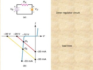
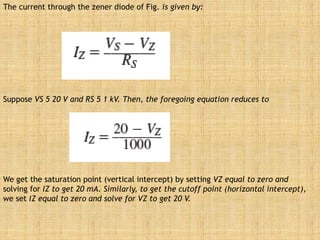
The current throughthe zener diode of Fig. is given by:
Suppose VS 5 20 V and RS 5 1 kV. Then, the foregoing equation reduces to
We get the saturation point (vertical intercept) by setting VZ equal to zero and
solving for IZ to get 20 mA. Similarly, to get the cutoff point (horizontal intercept),
we set IZ equal to zero and solve for VZ to get 20 V.
4.
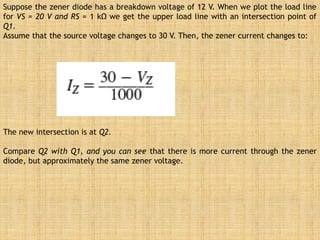
Suppose the zenerdiode has a breakdown voltage of 12 V. When we plot the load line
for VS = 20 V and RS = 1 kΩ we get the upper load line with an intersection point of
Q1.
Assume that the source voltage changes to 30 V. Then, the zener current changes to:
The new intersection is at Q2.
Compare Q2 with Q1, and you can see that there is more current through the zener
diode, but approximately the same zener voltage.
5.
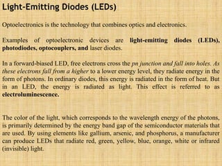
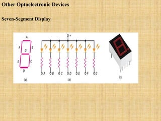
Light-Emitting Diodes (LEDs)
Optoelectronicsis the technology that combines optics and electronics.
Examples of optoelectronic devices are light-emitting diodes (LEDs),
photodiodes, optocouplers, and laser diodes.
In a forward-biased LED, free electrons cross the pn junction and fall into holes. As
these electrons fall from a higher to a lower energy level, they radiate energy in the
form of photons. In ordinary diodes, this energy is radiated in the form of heat. But
in an LED, the energy is radiated as light. This effect is referred to as
electroluminescence.
The color of the light, which corresponds to the wavelength energy of the photons,
is primarily determined by the energy band gap of the semiconductor materials that
are used. By using elements like gallium, arsenic, and phosphorus, a manufacturer
can produce LEDs that radiate red, green, yellow, blue, orange, white or infrared
(invisible) light.
7.
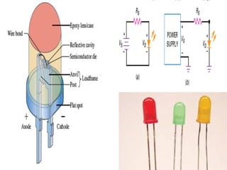
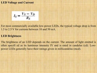
LED Voltage andCurrent
For most commercially available low-power LEDs, the typical voltage drop is from
1.5 to 2.5 V for currents between 10 and 50 mA.
LED Brightness
The brightness of an LED depends on the current. The amount of light emitted is
often specifi ed as its luminous intensity IV and is rated in candelas (cd). Low-
power LEDs generally have their ratings given in millicandelas (mcd).
8.
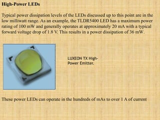
High-Power LEDs
Typical powerdissipation levels of the LEDs discussed up to this point are in the
low milliwatt range. As an example, the TLDR5400 LED has a maximum power
rating of 100 mW and generally operates at approximately 20 mA with a typical
forward voltage drop of 1.8 V. This results in a power dissipation of 36 mW.
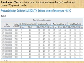
LUXEON TX High-
Power Emitter.
These power LEDs can operate in the hundreds of mAs to over 1 A of current
9.
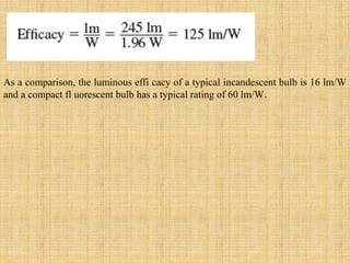
Luminous efficacy :-is the ratio of output luminous flux (lm) to electrical
power (W) given in lm/W.
10.
As a comparison,the luminous effi cacy of a typical incandescent bulb is 16 lm/W
and a compact fl uorescent bulb has a typical rating of 60 lm/W.
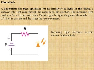
Photodiode
A photodiode hasbeen optimized for its sensitivity to light. In this diode, a
window lets light pass through the package to the junction. The incoming light
produces free electrons and holes. The stronger the light, the greater the number
of minority carriers and the larger the reverse current.
Incoming light increases reverse
current in photodiode.
13.
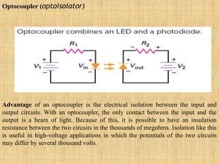
Optocoupler (optoisolator)
Advantage ofan optocoupler is the electrical isolation between the input and
output circuits. With an optocoupler, the only contact between the input and the
output is a beam of light. Because of this, it is possible to have an insulation
resistance between the two circuits in the thousands of megohms. Isolation like this
is useful in high-voltage applications in which the potentials of the two circuits
may differ by several thousand volts.
14.
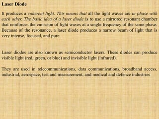
Laser Diode
It producesa coherent light. This means that all the light waves are in phase with
each other. The basic idea of a laser diode is to use a mirrored resonant chamber
that reinforces the emission of light waves at a single frequency of the same phase.
Because of the resonance, a laser diode produces a narrow beam of light that is
very intense, focused, and pure.
Laser diodes are also known as semiconductor lasers. These diodes can produce
visible light (red, green, or blue) and invisible light (infrared).
They are used in telecommunications, data communications, broadband access,
industrial, aerospace, test and measurement, and medical and defence industries
15.
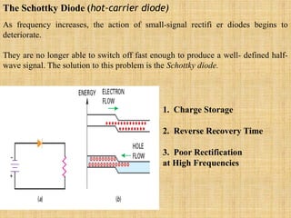
The Schottky Diode(hot-carrier diode)
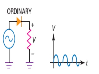
As frequency increases, the action of small-signal rectifi er diodes begins to
deteriorate.
They are no longer able to switch off fast enough to produce a well- defined half-
wave signal. The solution to this problem is the Schottky diode.
1. Charge Storage
2. Reverse Recovery Time
3. Poor Rectification
at High Frequencies
17.
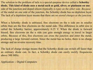
The solution tothe problem of tails is a special-purpose device called a Schottky
diode. This kind of diode uses a metal such as gold, silver, or platinum on one
side of the junction and doped silicon (typically n-type) on the other side. Because
of the metal on one side of the junction, the Schottky diode has no depletion layer.
The lack of a depletion layer means that there are no stored charges at the junction.
When a Schottky diode is unbiased, free electrons on the n side are in smaller
orbits than are the free electrons on the metal side. This difference in orbit size is
called the Schottky barrier, approximately 0.25 V. When the diode is forward
biased, free electrons on the n side can gain enough energy to travel in larger
orbits. Because of this, free electrons can cross the junction and enter the metal,
producing a large forward current. Since the metal has no holes, there is no charge
storage and no reverse recovery time.
The lack of charge storage means that the Schottky diode can switch off faster than
an ordinary diode can. In fact, a Schottky diode can easily rectify frequencies
above 300 MHz.
Application :- Digital Computers
18.
The Varactor
The varactor(also called the voltage-variable capacitance, varicap, epicap, and
tuning diode)
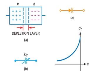
The depletion layer is between the p region and the n region. The p and n regions
are like the plates of a capacitor, and the depletion layer is like the dielectric. When
a diode is reverse biased, the width of the depletion layer increases with the reverse
voltage. Since the depletion layer gets wider with more reverse voltage, the
capacitance becomes smaller. It’s as though you moved apart the plates of a
capacitor. The key idea is that capacitance is controlled by reverse voltage.
20.
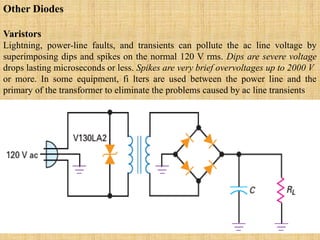
Other Diodes
Varistors
Lightning, power-linefaults, and transients can pollute the ac line voltage by
superimposing dips and spikes on the normal 120 V rms. Dips are severe voltage
drops lasting microseconds or less. Spikes are very brief overvoltages up to 2000 V
or more. In some equipment, fi lters are used between the power line and the
primary of the transformer to eliminate the problems caused by ac line transients
21.
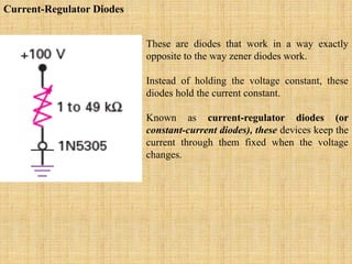
Current-Regulator Diodes
These arediodes that work in a way exactly
opposite to the way zener diodes work.
Instead of holding the voltage constant, these
diodes hold the current constant.
Known as current-regulator diodes (or
constant-current diodes), these devices keep the
current through them fixed when the voltage
changes.
22.
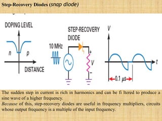
Step-Recovery Diodes (snapdiode)
The sudden step in current is rich in harmonics and can be fi ltered to produce a
sine wave of a higher frequency.
Because of this, step-recovery diodes are useful in frequency multipliers, circuits
whose output frequency is a multiple of the input frequency.
23.
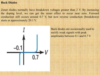
Back Diodes
Zener diodesnormally have breakdown voltages greater than 2 V. By increasing
the doping level, we can get the zener effect to occur near zero. Forward
conduction still occurs around 0.7 V, but now reverse conduction (breakdown)
starts at approximately 20.1 V.
Back diodes are occasionally used to
rectify weak signals with peak
amplitudes between 0.1 and 0.7 V.
24.
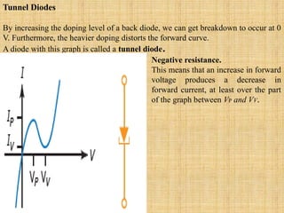
Tunnel Diodes
By increasingthe doping level of a back diode, we can get breakdown to occur at 0
V. Furthermore, the heavier doping distorts the forward curve.
A diode with this graph is called a tunnel diode.
Negative resistance.
This means that an increase in forward
voltage produces a decrease in
forward current, at least over the part
of the graph between VP and VV.
25.
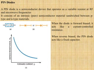
PIN Diodes
A PINdiode is a semiconductor device that operates as a variable resistor at RF
and microwave frequencies
It consists of an intrinsic (pure) semiconductor material sandwiched between p-
type and n-type materials.
When the diode is forward biased, it
acts like a current-controlled
resistance.
When reverse biased, the PIN diode
acts like a fixed capacitor.