Kirby morgan superlite_27_dive_helmet_manual
•
1 like•1,972 views

Manual do capacete para mergulho comercial Superlite 17. Em inglês.

Recommended
More Related Content
What's hot
What's hot (20)
Viewers also liked
Viewers also liked (17)
Similar to Kirby morgan superlite_27_dive_helmet_manual
Similar to Kirby morgan superlite_27_dive_helmet_manual (20)
Recently uploaded
Recently uploaded (20)
Kirby morgan superlite_27_dive_helmet_manual
- 1. Diving with compressed breathing gas is a hazardous activity. Even if you do everything right there is always the danger that you may be killed or injured. No piece of diving equipment can prevent the possibility that you may be killed or injured any time you enter the water. SuperLite® 27 Helmet Operations and Maintenance Manual KMDSI Part # 100-027 Kirby Morgan Dive Systems, Inc. 1430 Jason Way Santa Maria, CA 93455, USA Telephone (805) 928-7772, FAX (805) 928-0342 E-Mail: Info@KirbyMorgan.com, Web Site:www.KirbyMorgan.com Manual prepared by Marine Marketing and Consulting, Dive Lab, Inc., and KMDSI. NOTE: This manual is the most current for the SuperLite 27 Helmet. It is page dated May 2008. Future changes will be shown on page III and the changed pages will carry the date of change. Previous manuals may not reflect these updates. ™ Document Number 080528001 Kirby Morgan, SuperLite, BandMask, Band Mask, KMB, KMB-Band Mask, DSI, Diving Systems International, EXO, REX, SuperFlow and DECA are all registered trademarks of Kirby Morgan Dive Systems, Inc. Use of these terms to describe products that are not manufactured by KMDSI is illegal. The two dimensional images (such as photographs and illustrations) of our products are © copyrighted and trademarks of Kirby Morgan Dive Systems, Inc. The three dimensional forms of our products are trademark, trade design and trade dress protected. © Copyright 1970-2007 Kirby Morgan Dive Systems, Inc. All rights reserved. This manual is made available for the express use of the owner of this Kirby Morgan product. No part of this manual may be reproduced, stored in any retrieval system, or transmitted, or used in any form or by any means, whether graphic, electronic, mechanical, photocopy, or otherwise by technology known or unknown, without the prior written permission of Kirby Morgan Dive Systems, Inc. The SuperLite 27 helmet is CE Approved and meets or exceeds all performance and testing require- ments of all government and non-government testing agencies throughout the world. It is approved for use on all commercial and military work underwater. Only Kirby Morgan masks and helmets have achieved the CR (Commercial Rated) mark, the highest United States of America rating. WARNING
- 2. SuperLite 27 II © Copyright 1970-2008 Kirby Morgan Dive Systems, Inc. All rights reserved. Document # 080528001 WARRANTY INFORMATION Kirby Morgan Dive Systems, Inc. warrants every new mask, helmet, or KMAC Air Control System to be free from defects in workmanship for a period of ninety (90) days from date of purchase. This warranty covers all metal, fiberglass, and plastic parts. This warranty does NOT cover rubber parts, communications components, or headliners. In addition, due to the electrolytic nature of underwater cutting and welding, chrome plating cannot be warranted when the diver engages in these activities. Should any part become defective, contact the nearest authorized KMDSI dealer. If there is no dealer in your area, contact KMDSI directly at (805) 928-7772. You must have a return authorization from KMDSI prior to the return of any item, Upon approval from KMDSI, return the defective part, freight prepaid, to the KMDSI plant. The part will be repaired or replaced at no charge as deemed necessary by KMDSI. This warranty becomes null and void if: 1) The product is not registered with KMDSI within ten (10) days of purchase. 2) The product has not been properly serviced and/or maintained according to the appropri- ate KMDSI manual. In addition, the user is responsible to ensure that all product updates as recommended by KMDSI have been performed. 3) Unauthorized modifications have been made to the product. 4) The product has been abused or subjected to conditions which are unusual or exceed the product’s intended service. NOTE: Be sure to complete the enclosed warranty card and return it to KMDSI immediately. No war- ranty claims will be honored without a satisfactorily completed warranty card on file at KMDSI.
- 3. SuperLite 27 III© Copyright 1970-2008 Kirby Morgan Dive Systems, Inc. All rights reserved. Document # 080528001 It is the responsibility of the owner of this product to register their ownership with Kirby Morgan Dive Systems, Inc., by sending the warranty card provided. This card is to establish registration for any necessary warranty work and provides a means of communication that allows KMDSI to contact the user regarding this product. The user must notify KMDSI of any change of address by the user or sale of the product. All changes or revisions to this manual must be recorded in this document to ensure that the manual is up to date. RECORD OF CHANGES Change Number Date Description of Change Page Number 1 05/28/2008 Reworded: 2.1 Product Specifications, 2.4 Operational Specifi- cations & Limitations, Warning bottom left on page 23 Added: 2.2.1 SuperFlow® and SuperFlow® 350 Demand Regu- lators, 2.2.2 SuperFlow® 450 Performance, Appendix A2, 3 and 4. Moved: 2.3 Cage Code to page 23 Removed: Tables 1 and 2 from chapter 2 22-23, 146-153
- 4. SuperLite 27 IV © Copyright 1970-2008 Kirby Morgan Dive Systems, Inc. All rights reserved. Document # 080528001 Diving with compressed breathing gas is a hazardous activity. Even if you do everything right there is always the potential for serious injury or death. No one piece of diving equipment can prevent the possibility that you may be injured or killed any time you enter the water. We do not herein make any effort to teach the principles of diving.The information in this manual is intended for users of Kirby Morgan helmets and persons that maintain or service Kirby Morgan helmets. WARNING
- 5. SuperLite 27 V© Copyright 1970-2008 Kirby Morgan Dive Systems, Inc. All rights reserved. Document # 080528001 Contents Definition of Signal Words Used in this Manual X Chapter 1.0 - General Information KMDSI Products 15 1.1 Introduction 15 1.2 The Kirby Morgan Diving Helmets, Masks & Air Control System 16 Chapter 2 - Description & Operational Specifications - SuperLite-27 22 2.1 Product Specifications 22 2.2 Regulator Performance 22 2.3 Cage Code 22 2.4 Operational Specifications & Limitations 23 2.5 Helmet Features 25 2.6 General Description 28 2.6.1 Helmet Shell 28 2.6.2 Gas Flow Systems 28 2.6.3 Emergency Gas Supply System (EGS) 30 2.6.4 Helmet Attachment to the Diver 31 2.6.5 Locking Sealed Pull Pins 31 2.6.6 Sealing Arrangement 32 2.6.7 Reducing Carbon Dioxide 32 2.6.8 Communications 32 2.6.9 Equalizing the Middle Ear 32 2.6.10 Face Port or Viewing Lens 32 2.7 Accessories 33 2.7.1 Eye Protection for Welding 33 2.7.2 Hot Water Shroud 33 2.7.3 Helmet Carrying Bag 34 2.7.4 Special Regulator Tools 34 Chapter 3.0 Operating Instructions 35 3.1 Introduction 35 3.2 Design Purpose 35 3.3 First Use of Your Kirby Morgan Diving Helmet 37 3.4 Initial Adjustments to Your SuperLite 27 37 3.4.1 Head Cushion 37 3.4.2 Trimming the Neck dam 37 3.4.3 Adjusting the Neck Pad 38 3.5 Pre Dress-In Procedure 39 3.5.1 Pre-Dive Visual Inspection 39 3.6 Preparing the Helmet for Diving 40 3.6.1 Clean Face Port 40 3.6.2 Check Moving Parts 40 3.6.3 Check Communications 40 3.6.4 One Way Valve Check 40 3.7 Emergency Gas System (EGS) 40 3.8 Setting Up to Dive 45 3.8.1 Flushing Out the Umbilical 45 3.8.2 Connecting the Umbilical to the Helmet 45 3.8.3 Opening the Breathing Gas Supply to the Helmet 46 3.8.4 Fogging Prevention 46 3.8.5 Donning the Helmet 46 3.8.6 Testing the Breathing System 49 3.8.7 Sealing Integrity Check 49
- 6. SuperLite 27 VI © Copyright 1970-2008 Kirby Morgan Dive Systems, Inc. All rights reserved. Document # 080528001 3.9 Diving Procedures 50 3.9.1 Standing By to Dive 50 3.9.2 Attaching the Umbilical to the Harness 50 3.9.3 Diver Dons Helmet 50 3.9.4 Diver Check Gas Flow Systems 50 3.9.5 Communications Check 50 3.9.6 Diver Ready 50 3.9.7 Water Entry and Descent 50 3.9.8 Adjust Regulator for Low Work Rates 50 3.10 Emergency Procedures 52 3.10.1 Flooding 52 3.10.2 Inhalation Resistance 52 3.10.3 Gas Flow Stops 52 3.10.4 Demand Regulator Free Flow 52 3.11 Post Dive Procedures 53 3.11.1 Removing the Equipment 53 3.11.2 Removing the Helmet 53 3.11.3 Storage of the Helmet Between Dives 53 Chapter 4.0 Troubleshooting 54 4.1 General 54 4.2 Communication Malfunction 54 4.3 One Way Valve Malfunction 55 4.4 Side Block Malfunction 55 4.5 Water Leakage Into Helmet 55 4.6 Demand Regulator Malfunction 56 4.7 Emergency Gas Supply Valve 56 Chapter 5.0 Inspection 57 5.1 Daily Maintenance 57 5.2 Monthly Maintenance 57 5.3 Maintenance to be Performed Every Six Months 57 5.4 Yearly Maintenance 57 Chapter 6.0 General Preventative Maintenance 58 6.1 Introduction 58 6.2 Required tools, Cleaning Agents, Lubrication 58 6.2.1 Component and Parts Cleaning 59 6.2.2 Component and Parts Lubrication 59 6.2.3 Teflon Tape 60 6.2.4 RTV Sealant 60 6.2.5 Thread Locker 61 6.3 General Cleaning & Inspection Procedures 62 6.3.1 O-Ring Removal/Inspection/Cleaning and Lubrication 63 O-Ring Removal: 63 O-Ring Inspection: 63 O-Ring Reuse: 63 6.3.2 General Cleaning Guidelines 63 6.3.2.1 Soap Solution for General Cleaning and Leak Detector Use 63 6.3.2.2 Acidic Cleaning Solution and Procedures 63 6.3.2.3 Germicidal Cleaning Solutions and Procedure 63 6.4 Daily Maintenance 65 6.5 Monthly Maintenance (or between jobs) 66
- 7. SuperLite 27 VII© Copyright 1970-2008 Kirby Morgan Dive Systems, Inc. All rights reserved. Document # 080528001 6.5.1 Locking Collar Assembly & Helmet Ring 66 6.5.2 Neck Dam Ring Assembly 66 6.5.3 Head Cushion and Chin Cushion 67 6.5.4 Communications Inspection 67 6.5.5 Lubricate Nose Block O-Rings 67 6.5.6 Inspect the Exhaust Valve 67 Chapter 7.0 Breathing System Maintenance and Repairs 69 7.1 Introduction 69 7.2 Torque Values 69 7.3 One Way Valve 69 7.3.1 Disassembly Of The One Way Valve 69 7.3.2 Reassembly of the One Way Valve 70 7.4 Side Block Assembly 72 7.4.1 General 72 7.4.2 Side Block Assembly Removal 72 7.4.3 Separating the Side Block Assembly from the Helmet Shell 72 7.4.4 Side Block Assembly Replacement 74 7.5 Defogger Valve 76 7.5.1 Disassembly of the Defogger Valve 76 7.5.2 Cleaning and Lubricating 76 7.5.3 Reassembly of the Defogger Valve 77 7.6 Emergency Valve Assembly 78 7.6.1 Disassembly of the Emergency Valve 78 7.6.2 Cleaning and Lubricating 78 7.6.3 Reassembly of Emergency Valve 79 7.7 Bent Tube Assembly 81 7.7.1 General 81 7.7.2 Removal of the Bent Tube Assembly 81 7.7.3 Inspection of Bent Tube Assembly 81 7.7.4 Reinstallation of the Bent Tube Assembly 82 7.8 Demand Regulator SuperFlow 350 82 7.8.1 Demand Regulator Test for Correct Adjustment, Fully Assembled 83 7.8.2 Inspection of Regulator Body Interior 83 7.8.3 Demand Regulator Bias Adj. Servicing, Demand Regulator on Helmet 84 7.8.4 Reassembly of Adjustment System 85 7.8.5 Demand Regulator Assembly Removal from Helmet 85 7.8.6 Disassembly of the SuperFlow 350 Demand Regulator 86 7.8.7 Inspection of Demand Regulator Parts 88 7.8.8 Reassembly of the SuperFlow 350 Demand Regulator 89 7.8.9 Tuning the SuperFlow 350 Regulator 93 7.8.10 Regulator Steady Flows When Pressured Up: Special Tools Used 94 7.8.11 Regulator has Low or No Flow When Pressurized 96 7.8.12 Unexplained Demand Regulator Free Flow 96 7.9 Oral/Nasal 97 7.9.1 Oral/Nasal Removal 97 7.9.2 Inspection of Oral/Nasal 97 7.9.3 Oral/Nasal Replacement 97 7.10 Tri-Valve Exhaust 98 7.10.1 Tri-Valve™ Assembly Removal 98 7.10.2 Tri-Valve™ Exhaust Valve & Regulator Exhaust Valve Replacement 99 7.10.2.1 Tri-Valve™ Exhaust Valve Replacement 99 7.10.2.2 Regulator Exhaust Valve Replacement 100 7.10.3 Tri-Valve™ Assembly Installation 101 7.11 Main Exhaust Assembly Water Dump 102
- 8. SuperLite 27 VIII © Copyright 1970-2008 Kirby Morgan Dive Systems, Inc. All rights reserved. Document # 080528001 7.11.1 Water Dump Valve Removal 103 7.11.2 Water Dump Valve Replacement 103 7.11.3 Purge Valve Body Removal and Replacement 103 7.11.4 Purge Valve Body Installation 103 7.11.5 Water Dump Valve Body Removal 104 7.11.6 Water Dump Valve Body Remounting 104 7.12 Overpressure Relief / Bleed Valve Overhaul Procedures 105 7.12.1 Overpressure Relief Valve 105 7.12.2 Overpressure Relief Valve Disassembly and Cleaning 105 7.12.3 Overpressure Relief Valve Reassembly 106 7.12.4 Overpressure Relief Valve Lift Check/Setting 106 Chapter 8 Corrective Maintenance 108 8.1 General 108 8.2 Helmet Shell Inspection 108 8.3 Nose Block Assembly 109 8.3.1 Nose Block Assembly Removal 109 8.3.2 Nose Block Device Replacement 109 8.4 Handle and Weights 110 8.4.1 Handle Removal 110 8.4.2 Handle Replacement 110 8.4.3 Side Weight Removal 111 8.4.4 Weight Replacement 112 8.4.5 Diamond Weight Removal 112 8.4.6 Diamond Weight Replacement 112 8.5 Face Port 113 8.5.1 General 113 8.5.2 Face Port and Nose Block Device Removal 113 8.5.3 Face Port and Nose Block Replacement 114 8.5.4 Special Note Regarding Ports 116 8.6 Neck Dam 117 8.6.1 Removal of the Neck Dam 117 8.6.2 Neoprene Neck Dam Replacement 117 8.6.3 Latex Neck Dam Replacement 120 8.6.4 Trimming a Latex Neck Seal 121 8.7 Neck Dam Pull Strap 122 8.7.1 Neck Dam Pull Strap Removal 122 8.7.2 Neck Dam Pull Strap Replacement 122 8.8 Chin Strap 122 8.8.1 Chin Strap Removal 122 8.8.2 Chin Strap Replacement 122 8.9 O-Ring Seal Replacement 123 8.10 Helmet Ring 124 8.10.1 Helmet Ring Repairs 124 8.11 Sealed Pull Pins 124 8.11.1 Removal of Sealed Pull Pins 124 8.11.2 Replacement of Sealed Pull Pins 124 8.12 Swing Tongue Catch 125 8.12.1 Disassembly of the Swing Tongue Catch 125 8.12.2 Reassembly of the Swing Tongue Catch 126 8.13 Locking Collar 127 8.13.1 Locking Collar Removal 127 8.13.2 Locking Collar Disassembly 128 8.13.3 Locking Collar Reassembly 129 8.14 Head Cushion and Chin Cushion 130
- 9. SuperLite 27 IX© Copyright 1970-2008 Kirby Morgan Dive Systems, Inc. All rights reserved. Document # 080528001 8.14.1 Head Cushion Foam 130 8.14.2 Chin Cushion Foam 130 8.15 Communications System 131 8.15.1 General 131 8.15.2 Earphone Inspection 131 8.15.3 Removal of Communications Assembly 132 8.15.4 Replacement of Communications Assembly 132 8.15.5 Microphone Replacement 132 8.15.6 Earphone Replacement 133 8.15.7 Waterproof Connector 134 8.15.8.1 Connector Removal 134 8.15.8.2 Connector Replacement 134 8.15.9 Communications Posts 134 8.15.9.1 Communications Post Removal 134 8.15.9.2 Communications Post Replacement 135 Chapter 9.0 Accessories for the SuperLite 27 136 9.1 Introduction 136 9.2 Hot Water Shroud 136 9.2.1 Hot Water Shroud Installation Procedures 136 9.3 Low Pressure Inflator Hose 139 9.3.1 Installation of the Low Pressure Inflator Hose 139 9.4 Weld Lens Assembly 140 9.4.1 Weld Lens Assembly Installation 140 9.5 Weld Shield Assembly 141 9.5.1 Weld Shield Assembly Installation 141 9.6 Use of Quick Disconnect 141 Table of Equivalents 157 Appendix 1: Torque Specifications 158 Note on Torque Specifications 159 Appendix A2 - Maintenance and Inspection Procedures 160 Appendix 3 - Pressure Tables 148 Appendix 4 - Standard KMDSI Surface Supply Pressure Formula - Old Method 153
- 10. SuperLite 27 X © Copyright 1970-2008 Kirby Morgan Dive Systems, Inc. All rights reserved. Document # 080528001 DANGER CAUTION For your protection, pay particular attention to items identified by signal words in this manual. These terms are identified as, CAUTION, WARNING AND DANGER. It is especially important for you to read and understand these sections. This word indicates an imminently hazardous situation, which if not avoided, could re- sult in death or serious injury. This word indicates a potentially hazardous situation, which, if not avoided, could result in death or serious injury. This word indicates a potentially hazardous situation, which if not avoided, may result in minor or moderate injury. It may also be used to alert against unsafe practices. If English is not your native language and you have any difficulty understanding the language of any warnings as they appear in the manual, please have them translated. Este é um aviso importante. Queira mandá-lo traduzir. Este es un aviso importante. Sirvase mandario traducir. Quest è un avviso importante.Tradurlo. Ceci est important. Veuillez traduire. Diese Mitteilung ist wichtig. Bitte übersetzen lassen. If you have any questions concerning this manual or the operation of your helmet, contact KMDSI (805) 928-7772 or by Email at info@KMDSI.com or Dive Lab Inc. (850) 235-2715 or at Divelab@aol.com IMPORTANT: A word about this manual. We have tried to make this manual as comprehensive and factual as possible. We reserve the right, however, to make changes at any time, without notice, in prices, colors, materials, equipment, specifications, models and availability. Since some information may have been updated since the time of printing, please contact your local KMDSI dealer if you have any questions. Periodically KMDSI Operations and Maintenance Manuals are reviewed. Any updates/changes will be posted on the KMDSI website and may be down- loaded for insertion/correction. Important Safety Information: This SuperLite 27 diving helmet is intended for use by trained divers who have successfully completed a recognized training course in surface supplied diving. Definition of Signal Words Used in this Manual WARNING WARNING WARNING WARNING WARNING WARNING
- 11. SuperLite 27 XI© Copyright 1970-2008 Kirby Morgan Dive Systems, Inc. All rights reserved. Document # 080528001 WARNING Follow all the instructions in this manual carefully and heed all safety precautions. Im- proper use of this diving helmet could result in serious injury or death. Kirby Morgan Dive Systems, Inc. (KMDSI) warns all divers who use Kirby Morgan div- ing helmets or masks to be sure to use only KMDSI original parts from a KMDSI au- thorized dealer. Although other parts, O-rings and fittings may appear to fit your Kirby Morgan diving helmet or mask, they may not be manufactured to the same standards maintained by KMDSI.The use of any parts other than KMDSI original parts may lead to equipment failure and accidents. Diving in waters that are chemically, biologically, or radiologically contaminated is ex- tremely hazardous. Although Kirby Morgan diving helmets may be adapted for use in some contaminated environments, special training, equipment, and procedures are necessary. Do not dive in a contaminated environment unless you have been thoroughly trained and equipped for this type of diving. Read this manual before using or maintaining the helmet, even if you have experience with other diving helmets. If you have purchased the helmet new from a dealer, be sure to send in the warranty registration card so we may keep you informed of any safety notices that affect this product. If you resell or loan this helmet to another diver, be sure this manual accompanies the helmet and that the person reads and understands the manual. In addition to the manual a log book should be used to log all repairs, maintenance and use. Diving is a life threatening occupation. Even if you do everything right you can still be killed or injured. None of the models of Kirby Morgan helmets or masks can prevent ac- cidents, injuries or death due to improper training, poor-health, improper supervision, improper job requirements, improper maintenance or acts of God. This helmet was completely checked and should be ready to dive as it was shipped from the factory. However, it is always the diver’s responsibility to check all the compo- nents of the helmet prior to diving. Any and all fiberglass repairs done to this helmet MUST be done by a KMDSI factory trained repair facility. Painting is not recommended by KMDSI. Furthermore, many div- ing companies will not allow painted helmets to be used because painting can mask previous fiberglass damage. KMDSI certified technicians are not responsible for certify- ing helmets free from damage during annual overhauls. Helmet shells can be re-gel coated by authorized/certified KMDSI trained technicians that have received fiberglass training by KMDSI. Helmets that are to be painted for cosmetic purposes, should be first, certified free of fiberglass damage by an authorized KMDSI technician certified in fiberglass repair. A log entry should be made in the hel- met log that the helmet was free of damage prior to painting. Keep in mind other KMDSI technicians can refuse to work on helmet shells that have previously been painted or repaired by non KMDSI certified persons. This manual is supplied to the original purchaser of this helmet. If you have any questions about the use of the helmet or you need another copy of this manual, contact KMDSI or your nearest KMDSI dealer. It may also be downloaded free from the KMDSI website at www.KirbyMorgan.com. WARNING WARNING WARNING WARNING WARNING
- 12. SuperLite 27 XII © Copyright 1970-2008 Kirby Morgan Dive Systems, Inc. All rights reserved. Document # 080528001 If you have any questions regarding the use, maintenance, or operation of this helmet, contact KMDSI at (805) 928- 7772, fax: (805) 928-0342, or e-mail: info@kirbymorgan.com. Kirby Morgan masks and helmets are cleaned and lubricated for oxygen ser- vice when they come from the factory. However, if the helmet is used with an oil lubricated air compressor, contamination with hydrocarbons may result. If the breathing system in the helmet is exposed to hydrocarbons, it must be cleaned for oxygen service and lubricated with oxygen safe lubricants before using it again with breathing mixtures containing a high percentage of oxy- gen. If this is not done, fires and explosions may result, exposing the user to serious personal injury or death. Components requiring lubrication, should only be lubricated with oxygen compatible lubricants such as Christo Lube®, Flourolube®, or Krytox® . Lubricants must be used sparingly and should not be mixed with other lubricants. KMDSI helmets and masks are intended for underwater use only and should only be used by qualified divers that have received proper training in the use of this type of equipment. KMDSI helmets and masks should not be used or worn without the appro- priate life support systems, such as air or gas supplies and support personnel as de- scribed in this manual. KMDSI helmets and masks should never be used for motor sport racing, aviation / space craft use, or for chemical warfare use.The helmet must never be used by persons in poor physical condition, by persons with previous head, neck, or back injuries which could be aggravated by its use.The helmet should not be used by persons under the in- fluence of drugs or alcohol. Furthermore, infants, children, or persons under the age of 18 should never wear KMDSI helmets and masks. Failure to pay heed to the above could result in serious injury or death. Never use the helmet without first completing all pre-dive maintenance and set up pro- cedures. Do not use KMDSI masks or helmets in currents exceeding 3.0 knots Use in currents greater than 3 knots may allow water to enter the exhaust valve, possibly causing regu- lator flooding. Surface-supplied diving can be a strenuous activity.The SuperLite 27 weighs approxi- mately 30 lbs. KMDSI recommends that persons with a previous neck or back injury seek professional medical approval prior to engaging in surface supplied diving opera- tions using the SuperLite 27. Use of the SuperLite 27 with a pre-existing physical/medi- cal condition may result in death or serious injury. The information contained in this manual is intended to aid the user in optimizing the performance of this helmet. The application of some of this information will depend on the diving situation and the use of associated equipment. Many countries have specific laws and rules regarding commercial diving. It is important for the user to understand the rules, regulations, and philosophy imposed by the governing, regulating bodies whenever using commercial diving equip- ment. WARNING WARNING WARNING WARNING WARNING
- 13. SuperLite 27 XIII© Copyright 1970-2008 Kirby Morgan Dive Systems, Inc. All rights reserved. Document # 080528001 Whenever KMDSI helmets or masks are used in European Countries, which have adopted the C.E. certification pro- grams, they must only be used with C.E. certified components. Diving operations should only be conducted within the limits of the operational specifications, and in accordance with the rules and regulations established by the governing authority in the specific country or geographical location where the diving operations are being conducted. If you have any questions concerning this manual or the operation of your helmet, contact KMDSI (805) 928-7772 or at info@ KMDSI.com or Dive Lab Inc. (850) 235-2715 or at Divelab@aol.com WARNING Always read the Material Safety Data Sheet (MSDS) for any chemical - adhesive, clean- ing agent, or lubricant - used on your Kirby Morgan helmet. Some of these chemicals may cause serious bodily injury or death if used improperly or without the proper per- sonal protective equipment.
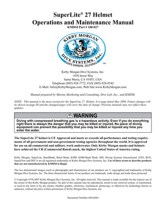
- 14. SuperLite 27 XIV © Copyright 1970-2008 Kirby Morgan Dive Systems, Inc. All rights reserved. Document # 080528001 Handle Sideblock Port retainer Non-return valve EGS valve Helmet shell The SuperLite 27 helmet Defog free flow valve knob Tri-Valve Exhaust standard on all SuperLite 27 helmets Regulator adjustment knob Communications port Pull pin Equalization device Oral nasal mask COMME RCIALLY RATED - P ROFESSIONALDIVI NG GEAR-DIVELA B TESTED ™
- 15. SuperLite 27 15© Copyright 1970-2008 Kirby Morgan Dive Systems, Inc. All rights reserved. Document # 080528001 This manual will refer to location numbers in specific drawings, or in the exploded view, which is in the back of this manual.These numbers are called “location” numbers.They are used to find the referred to parts in the drawings in this manual only. They are not the part number. Next to the exploded drawing is a list of the “location” numbers that match the Kirby Morgan part numbers along with the name of the part. Always check the part number when ordering to make sure it is correct. When ordering, always specify the helmet model number and serial number as well. The Kirby Morgan Corporation was started in 1965. The copper and brass “heavy gear” or “Standard Dress” helmets were the first helmets manufactured by the company. Over the years Kirby Morgan de- signed, manufactured and sold many different helmets and masks for commercial divers. Staying active in commercial diving has contributed to the successful design innovations of KMDSI prod- ucts. This may be the primary reason for the accep- tance of our designs by professional divers. Bev Morgan has designed more than seventy seven (77) diving helmets and over 40 diving masks. All employees of KMDSI participate as part of the Kirby Morgan design team. It would not be possible for us to supply the commercial, military, scientific, and public service diving industries with our equip- ment, without the team of people that make up Kirby Morgan Dive Systems, Inc. (KMDSI) We feel it is important for the reader to understand that we at KMDSI consider ourselves as only part of the process along the path in diving equipment design. We welcome all input from our customers. The thinking of many good divers, diving equip- ment engineers, diving medical specialists, diving organization administrators and their supporting personnel has contributed to the current state of the art of diving. Each piece of gear we manufacture has in it some of the thinking of those who have gone before us. To all those people who gave something of themselves to the men and women who work underwater, we express a thank you. We have a strong commitment to providing the best diving equipment and service possible. This thinking has been the policy of Kirby Morgan Dive Systems, Inc. and we will continue to take this approach to our work. Our extensive dealer network makes it easy to obtain genuine Kirby Morgan replacement parts, as well as technical assistance worldwide. Chapter 1.0 General Information KMDSI Products 1.1 Introduction Bev Morgan, Chairman of the Board Kirby Morgan Dive Systems, Inc. STOP! BEFORE GOING FURTHER-
- 16. SuperLite 27 16 © Copyright 1970-2008 Kirby Morgan Dive Systems, Inc. All rights reserved. Document # 080528001 KMDSI has always concentrated on designing and manufacturing diving equipment that allows most repairs, inspections, and all routine maintenance to be performed by the user. Most routine preventative and corrective maintenance can be accomplished by the user utilizing this manual, the KMDSI Tool Kit (P/N 525-620) and common hand tools. Technician training is available through Dive Lab Inc., informa- tion can be obtained on line at www.divelab.com or by telephone at 850-235-2715. 1.2 The Kirby Morgan Diving Helmets, Masks & Air Control System All Kirby Morgan diving helmets and masks are manufactured by Kirby Morgan Dive Systems, Inc. (KMDSI). Each step of the manufacturing process is carefully controlled to assure the customer of a high quality, durable helmet that will function properly for many years. The models of Kirby Morgan diving helmets currently in production are the SuperLite-17B, MK-21 (U.S. Navy version), the SuperLite-27,and the Kirby Mor- gan 37, 47, and 57. All are commercially rated and marked. The SuperLite-17B was first developed in 1975 and quickly set a new standard for diving helmet design. Many large and small commercial diving companies, military organizations, scientific divers, and public safety divers are successfully using this design around the world. The SL-17B helmet system consists primarily of two major components: the neck dam/yoke assembly, and the helmet. To don the helmet, the diver first slips the angled neck dam with the attached yoke over his head. The helmet is lowered onto the diver’s head with the help of a tender, then the yoke hinge tab is hooked onto the alignment screw on the rear weight. The neck clamp is then slipped onto the helmet and locked. The locking system not only seals the neck dam to the helmet but also secures the front of the yoke, fastening the helmet to the diver’s head. The SuperLite-17A/B shares many common breath- ing system parts with all Kirby Morgan helmets and masks. The breathing system has been man-tested to 1600 FSW by the University of Pennsylvania and ap- proved by the U.S. Navy for surface-supplied diving to 190 FSW with air and to 300 FSW with mixed gas SuperLite 17A/B Kirby Morgan 37 Yoke and Latch Catch Assembly Neck Pad and Sealed Pull Pins. approved and marked marked COMME RCIALLY RATED - P ROFESSIONALDIVI NG GEAR-DIVELA B TESTED ™
- 17. SuperLite 27 17© Copyright 1970-2008 Kirby Morgan Dive Systems, Inc. All rights reserved. Document # 080528001 (helium and oxygen). It surpasses all requirements of all governing agencies and it is approved for com- mercial diving through out the world. Other features that are common to all Kirby Morgan helmets and Band Masks include: * Face port and retainer ring * Communications components * Oral/nasal mask * Nose block device * Air train defogger The Kirby Morgan 37 Commercial Diver’s Helmet represents what we at Kirby Morgan consider to be a turning point in modern diving helmet design. The helmet consists of two major assemblies: the helmet shell/helmet ring assembly and the neck dam/neck ring assembly. The helmet comes with the large tube SuperFlow 350 adjustable demand regulator which provides an easier breathing gas flow during peak work output. A quick change communications module is available with either bare wire posts or a waterproof connector. The helmet ring houses the sealed pull pins and pro- vides protection for the bottom end of the helmet. This custom fit and balance seats the helmet comfort- ably for long periods of time even when working in the face down position. The SuperLite 27 Commercial Diver’s Helmet has all the same features of the KM37 on a smaller, low volume shell design. This helmet is often preferred by persons with smaller heads. The chrome plated machined brass helmet neck ring houses the sealed pull pins and provides protection for the bottom end of the helmet. Like the SL-17K, 37 and 17C, the diver is provided with an adjustable chin support. This support, along with the adjust- able neck pad on the locking collar, gives the diver a comfortable, secure, custom fit. The quick-change communications module, available with either bare wire posts or a waterproof connector, allows for easy, efficient maintenance of the helmets communications. The helmet also features the SuperFlow 350 large tube adjustable demand regulator. The helmet is available in the umbilical over the shoulder, “B” configuration only. approved and marked SuperLite 27
- 18. SuperLite 27 18 © Copyright 1970-2008 Kirby Morgan Dive Systems, Inc. All rights reserved. Document # 080528001 The Kirby Morgan 57 helmet features our revo- lutionary new SuperFlow 450 Stainless Balanced Regulator. It's machined from a stainless steel cast- ing for the ultimate in performance and durability. This commercially rated regulator delivers all the breathing gas you need for the most demanding work underwater. In 2005, Kirby Morgan introduced three new helmets. The Kirby Morgan 47 offers the ultimate in a high performance breathing regulator. This helmet has an entirely new breathing system, oral nasal mask, and water ejection system. The Rex® Demand Valve (pat- ents pending), with it's fully adjustable balanced pis- ton is a breakthrough design that exceeds the require- ments of all government or other testing agencies. It has the best work-of-breathing performance when compared to ANY other commercial diving helmet. The Kirby Morgan 47 Dive Helmet has been tested and meets or exceeds European requirements and is fully commercially rated. In all other respects, this helmet is nearly identical to the Kirby Morgan 37. The Kirby Morgan 57 also includes our Quad- Valve™ Exhaust System. It's recommended for div- ing in biologically contaminated water, when you're properly trained and equipped, using recommended procedures. This new exhaust has exceptionally low exhalation resistance that you must experience to appreciate. lon The Kirby Morgan 67 Diving Helmet continues in our long tradition of innovation, providing the high- est quality and superior performance that divers have come to expect in a Kirby Morgan product. At first glance, you'll notice that the helmet features our revo- lutionary new SBR-1™ Stainless Balanced Regulator and has a different port design, but the differences go much deeper than just the visual. Our new UltraView™ Port design isn't just wider, it's also thicker, much thicker, which is essential to your safety when your port is this wide. It's also through bolted, which is unheard of in a diving helmet, but makes sense when you think about it. If you ever strip a retainer bolt, which is unlikely given their size, just replace it and its special securing nut without special tools or procedures. COMME RCIALLY RATED - P ROFESSIONALDIVI NG GEAR-DIVELA B TESTED ™ marked ® ® marked marked ™ Kirby Morgan 47 Kirby Morgan 57 Kirby Morgan 67
- 19. SuperLite 27 19© Copyright 1970-2008 Kirby Morgan Dive Systems, Inc. All rights reserved. Document # 080528001 The Kirby Morgan 77 represents the first in a new generation of stainless steel diving helmets that pro- vide an alternative for the diver who prefers a metal helmet. The helmet features a stainless steel version of our new REX® regulator, which offers the best performance of any Kirby Morgan system. The advantages of an all stainless steel helmet include the following: • No refinishing required if the surface is scratched or gouged. • Faster production of helmets for customer deliv- ery. • Elimination of threaded inserts for securing the port retainer to the helmet shell. Kirby Morgan 77 marked ®
- 20. SuperLite 27 20 © Copyright 1970-2008 Kirby Morgan Dive Systems, Inc. All rights reserved. Document # 080528001 The EXO Full Face Mask is designed for both surface supplied and scuba diving. By enclosing the divers eyes, nose and mouth, the EXO permits nearly normal speech when used in conjunction with most wireless, and all hardwire underwater communica- tion systems. The ORIGINAL EXO (not shown) design comes with automatic defogging, no oral nasal mask or nose block device (optional conversion kits available). The Mask Frame is black. TheEXOBR(BALANCEDREGULATOR)shown here is designed to meet or exceed recommended performance goals in both scuba and surface supplied modes and is approved. It meets and surpasses European standards for regulator performance. EXO BR approved and marked KMB 18 A/B marked The KMB 18B Band Mask frame is constructed of hand laid fiberglass. The head harness is a molded, strong tear resistant neoprene rubber. The hood, which attaches to the mask frame with welded stain- less steel bands, provides warmth for the diver’s head as well as pockets for the earphones. The communi- cations connections can be either a male waterproof plug-in type or bare wire posts. The KMB 28B Band Mask (not shown) is very simi- lar to the KMB 18, with many parts on the KMB 18B being interchangeable with the KMB 28B. The major difference between the 18 and 28 is the material of the mask frame itself. The KMB 18 has a fiberglass frame (yellow) while the KMB 28B frame is an extremely durable injection molded plastic (black). Other differences include: 1) The main exhaust body of the KMB 28 is part of the frame itself and uses a #545-041 main exhaust cover. 2) No comfort insert is required on the 28. 3) The face ports for the 18 and the 28 differ slightly in size. The Balanced Regulator helps reduce the work of breathing for the diver by balancing the intermediate air pressure against the valve sealing pressure inside the regulator. This enables the regulator to instantly adjust to changes in line pressure. The Balanced Regulator is adjustable for a wide range of intermedi- ate pressures between 100 PSI - 230 PSI. Both models have a modular communications design that permits rapid and simple maintenance. The optional Hard Shell provides surfaces for mounting lights, cameras etc.
- 21. SuperLite 27 21© Copyright 1970-2008 Kirby Morgan Dive Systems, Inc. All rights reserved. Document # 080528001 The SuperMask M-48 is an innovative new design in a full-face mask. It provides the diver with all the comfort of a full-face mask with the convenience of changeable second stage regulators as well as the ability to use a snorkel without having to remove the mask. The mask is comprised of two major components, the mask frame and the interchangeable lower pod. The removable lower pod is a feature unique to the SuperMask full-face mask. When diving, the pod is easily removed and replaced on the mask, providing the diver the capability to buddy-breathe, snorkel, use an octopus or perform an “in water” gas switch. With the pod sealed to the mask, the flexible, silicone pod cover allows the diver to quickly place the regula- tor mouthpiece into the mouth or dive with it free of the mouth for communications. With the mouthpiece in, the regulator may be used without the pod being sealed to the mask. The mask may also be used surface supplied. We are currently developing several different pod configura- tions for both open circuit and rebreather use. For fur- ther information, see the Frequently Asked Questions (FAQ) area on our web site at www.KirbyMorgan. com/products/faq.html TheKirbyMorganAirControlSystem-5(KMACS- 5) is a lightweight, portable control box for use in surface supplied air diving operations. The KMACS-5 controls the diver’s air supply, communications and monitors the diver’s depth. It allows two divers clear push-to-talk (two wire) or round robin (four wire) communications. The KMACS-5 is also available without communications. The air supply can be either from a low-pressure compressor or high-pressure cylinders. The adjust- able first stage regulator reduces the high-pressure air and supplies low pressure through the umbilical to the diver’s breathing system. High pressure yokes with DIN adapters permit both U.S. standard scuba cylinders and European DIN cylinders to be used. Low-pressure air supply fittings allow for a compressor to be used as the primary air source. A complete pneumo system with dual reading gauges (both US Standard and Metric) is provided for each diver’s air, as well as a shut-off/bleed system that uses two high-pressure feed lines which allows changing of used cylinders without interruption of the diving operation. Optional shut off valves allow the isolation of each diver’s air supply. The Communication Set is a multipurpose intercom- munication system that provides reliable and clear communications between a topside operator (tender) and one or more surface-supported divers, recompres- SuperMask M-48 w/ Scuba Pod SuperMask M-48 w/ Rebreather pod KMACS-5 w/ No Comunications KMACS-5 w/ Communications marked
- 22. 22 © Copyright 1970-2008 Kirby Morgan Dive Systems, Inc. All rights reserved. Document # 080528001 SuperLite 27 Chapter 2 Description & Operational Specifications This section includes a detailed decsription of the this Kirby Morgan Helmet as well as important op- erational specifications. 2.1 Product Specifications Weight: 27 pounds Helmet Shell: Fiberglass, polyester resin, and carbon fibers Control Knobs: ABS plastic Lens: Clear polycarbonate Neck Dam: Neoprene. Optional latex neck dam avail- able. O-Rings: Buna-N Head Cushion: Nylon bag filled with #4 Polyester foam The recommended lubrication type for breathing gas mixtures containing oxygen percentages greater than 50% is Christo Lube® , Krytox® , and Halocarbon® . Helmet gas train components being used with gas mixtures containing less than 50% oxygen can be lubricated with food grade silicone grease such as Dow Corning® 111. Never use aerosol-propelled sprays near the face port of any Kirby Morgan diving helmet. The propellant used in these aerosols can invisibly damage the face port and cause it to shatter on impact from any strong blow. If the face port fails underwater, injury or death may result. DANGER The helmet has been tested and conforms to the performance requirements as set forth in Annex II of Directive 89/686/EEC and as far as applicable, the EN250 (edition Jan 2000) and the E DIN 58 642 (edition Feb 1998). When the helmet is used for air diving in countries that conform to C.E. regulations it may be used to a maximum depth of 164fsw (50 msw). I.A.W. EN250. If you have any questions regarding proper set-up, op- eration, or maintenance of your SuperLite-27 contact KMDSI (850) 928-7772 or kmdsi@KirbyMorgan. com or Dive Lab Inc. (850) 235-2715 or Divelab@ aol.com 2.2 Regulator Performance 2.2.1 SuperFlow® and SuperFlow® 350 Demand Regulators The SuperFlow 350 non balanced regulator is the standard demand regulator found on the SL-27, KM-37 and KMB 18/28 Band Masks. NOTE: Pre Sep. 2004 KMB 28 plastic frames will only except the smaller mount tube found on the SuperFlow (non 350) regulator. The SuperFlow 350 is fully CE marked and CR rated. The SuperFlow 450 SS balanced regulator can be used on the SL-27, KM-37 and KMB-18/28 band Masks. Breathing performance is greatly affected by the support equipment used, as well as the supply pressure to the helmet or mask. 2.2.2 SuperFlow® 450 Performance The SuperFlow® 450 is an all Stainless Steel regula- tor of a balanced design that offers a slightly higher degree of breathing performance and extreme breath- ing rates, more than the non balanced SuperFlow regulator. This manual is our effort to explain the operation, maintenance and use of the SL 27. We do not herein make any effort to teach the principles of diving. It is our assumption the reader is a quali- fied diver. We highly recommend that all divers should train under controlled conditions, in the use of any commercial diving helmet that they have not previously used, or trained in, prior to use on the job. WARNING
- 23. SuperLite 27 23© Copyright 1970-2008 Kirby Morgan Dive Systems, Inc. All rights reserved. Document # 080528001 2.3 Cage Code The cage code for identifying KMDSI products for U.S. government purchase purposes is 58366. 2.4 Operational Specifications & Limitations This helmet meets or exceeds all performance require- ments and is fully CE marked with the SuperFlow® and SuperFlow® 350 non balanced regulator and is CR rated by Dive Lab Inc. The helmet when equipped with the SuperFlow® 450 SS balanced regulator is CR rated but not currently CE certified. CE certification is scheduled for late 2008 Every model of KMDSI helmets and masks undergo extensive type testing to fully document the perfor- mance capability and required supply pressures when using various umbilical and pressure combinations. All users should take the time to become knowledge- able on supply requirements to insure proper perfor- mance and for the comfort and safety of the diver. The required supply pressures for the KM-37 equipped with either the SuperFlow® 350 or SuperFlow® 450 regulators are listed in the appropriate supply pressure tables in Appendix 3. The supply pressures listed in the supply tables were derived by breathing simulator trials. There are two tables used for the SuperFlow® and SuperFlow® 350 regulators and two separate tables for the SuperFlow® 450 regulator. It is important that users understand how to use the tables. For further information on sup- ply requirements for the KM-37® or any Kirby Morgan helmet or mask check the Kirby Morgan website at www.kirbymorgan.com. -Umbilical minimum I.D. 3/8” (9.5 mm) of not more than two sections, total length not to exceed 600 feet (183m). -Temperature Limitations: Use at water temperatures below 33°F (1°C) requires the use of hot water shroud PN# 525-100 and hot water to help prevent icing of the demand regulator. It is important for the user/diver to take excessive currents into consideration. The Tri-Valve Exhaust® system (Part # 525-755) which is now standard, will help prevent wa- ter intrusion when diving in heavy currents. Unlike the old double exhaust, the Tri-Valve does not limit the diving depth. WARNING Decompression diving always involves the risk of decompression sickness. Omitted decompression due to a loss of the breath- ing gas supply or other accidents can cause serious injury or death. Use of a Kirby Morgan helmet or full-face mask cannot prevent this type of injury. DANGER WARNING The demand regulator and side block assemblies have a maxi- mum design pressure of 250 psig over the ambient pressure, higher pressures could lead to component failure resulting in serious injury. NOTE The Hot Water Shroud (Part #525-100) in conjunction with hot water to the diver should be used whenever diving operations are conducted using HEO2 at water temperatures less than 60°F (15.56°C) for the comfort of the diver. KMDSI further recommends that the shroud be used in conjunction with hot water to the diver whenever diving operations are conducted using air or mixed gas, in waters colder than 33°F (1°C) to reduce the possibility of demand regulator icing. NOTE: Usually the greatest danger of demand regulator icing will be encountered on deck when the surrounding air temperature is less than 32°F (0°C). This effect is primarily due to the refrigera- tion effect of breathing air pressure reduction, and the addition of moisture from the divers exhalation coming in contact with the topside air tempera- ture. If diving where the water temperature is 33°F (1°C) or warmer but the topside air temperature is below freezing, 32°F (0°C) icing of the demand regulator is possible. To help eliminate the possibil- ity of freezing on the surface, warm water should be run over the exterior of the demand regulator prior to water entry, if the hot water system is not used. Only equipment certified and tested according to EN 250/E DIN 58 642 may be used with the KM 37 helmet when conducting diving operations in European EC compliant countries. The umbilical assembly should be composed of good quality diving hose that meets industry standards. Generally, gas hose will be married to the commu- nications wire, pneumofathometer hose, and strength member in a manner that will allow the strength
- 24. 24 © Copyright 1970-2008 Kirby Morgan Dive Systems, Inc. All rights reserved. Document # 080528001 SuperLite 27 Gas systems used to supply Kirby Morgan helmets and masks must be capable of sup- plying gas to the diver at the required pres- sure and flow rates as stated in the opera- tional specifications. The use of unregulated gas sources is extremely dangerous. The use of standard SCUBA type regulators is unacceptable, as there are no provisions for adjusting the intermediate pressure to the diver. Only proven systems that allow for varying the gas supply pressure to the diver should be used for umbilical diving. WARNING member to receive all the strain. There are also good quality umbilicals available that are assembled at the factory using a twisted method which does not require marrying. Regardless of the system used, the umbilical is the diver’s life line and should always be of excellent quality and maintained carefully. If you have any questions regarding proper set-up, operation, or maintenance of your Kirby Morgan 37/57 helmet contact KMDSI (850) 928-7772 or at kmdsi@kirbymorgan.com or Dive Lab Inc. (850) 235-2715 or at Divelab@aol.com. This helmet meets or exceeds all requirements of NPD, CE, Health and Safety, (U.K.), United States Navy, ADCI United States and is CR rated by Dive Lab, Panama City, Fla., USA.
- 25. SuperLite 27 25© Copyright 1970-2008 Kirby Morgan Dive Systems, Inc. All rights reserved. Document # 080528001 2.5 Helmet Features All Kirby Morgan diving helmets are manufactured by hand. Each step of the manufacturing process is carefully controlled to assure the customer a high quality, durable helmet that will function properly. The SL 27 was developed in 1991. The goal was to bring together all of the top design elements of the various SuperLite helmets and then refine the mix into what we at KMDSI consider to be an outstand- ing diving helmet design. The SL 27 takes the best design features of our world famous SuperLite-17B and blends in many advanced design features. Add in some fine tuned balance refinements and you have a low volume diving helmet. Exemplifying our adher- ence to the highest quality and proven superior work performance, the SL 27 is one of the standards of the commercial diving industry worldwide. The SL 27 incorporates an innovative locking system and the SuperFlow 350 large tube adjustable demand regulator which provides an outstanding breathing gas flow during peak work output. The helmet consists of two pieces: the helmet shell/ helmet ring and the neck dam neck ring assembly. The machined brass helmet ring houses the latch catches and provides protection for the bottom end of the helmet. It also mounts an externally adjustable chin support. This support, along with the adjustable neck pad on the locking collar, gives the diver a se- cure, custom tailored fit in the helmet. This custom fit and balance seats the helmet comfortably for long periods of time even when working in the face down position. A quick change communications module, available in either bare wire posts or a waterproof connector, allows for easy, efficient maintenance of the commu- nications in the helmet. The SL 27 is configured to receive the umbilical over the shoulder. In the past, the optional Double Exhaust System (Part # 525-102) was available to reduce the possibility of back flow of water and contaminants into the helmet. This system has been used successfully for diving in biologically contaminated environments for many years. To further reduce the possibility of water intru- sion regardless of the exhaust system being used, the diver should avoid working in an inverted position. The double exhaust was replaced by the Tri-Valve™ System. The unique design of the Tri-Valve™ helps keep exhalation resistance low while maintaining excellent watertight integrity. WARNING Before attempting any diving in any type of contaminated water, a complete diving and topside course in hazardous materi- als emergencies should be completed. The divers and the topside team must be properly trained and have the proper safety equipment. All helmets and suits can leak water under certain conditions. Divers should use extreme caution when diving in contaminated waters. For more information see the book “Diving in High-Risk Environments” by Steven M. Barsky. The Tri-Valve™ exhaust system is now standard equipment for the SL 27. This superior exhaust system has exceptionally low exhalation resistance, and helps to keep the helmet free of contaminants in polluted water. The Tri-Valve™ isolates the breathing system from the surrounding water with a three valve, low breathing resistance design (Patents Pending). The Tri-Valve™ is designed to couple the regulator exhaust with the helmet main exhaust and route them into a single plenum chamber, mounted between the regulator body and main exhaust body. The exhaust gas then must pass through either one of two (or both) exhaust valves that are part of the bubble deflector (whisker). By having an exhaust valve in both sides of the bubble deflector, exhalation resistance is mini- mized, while still helping to maintain the isolation of the main helmet and regulator exhaust valves. In addition, the water dump valve now has two one- way valves to further help protect the diver in polluted water. When diving in heavy current (i.e. exceed- ing 3 knots) the single exhaust system on all KMDSI masks/helmets could allow water to enter, due to turbulence/eddying. It is important for the user/diver to take excessive currents into consideration. The Tri-Valve Exhaust® system (Part # 525-755) will help prevent water intrusion when diving in heavy currents. The Tri- Valve provides exceptionally low exhala- tion resistance. CAUTION
- 26. 26 © Copyright 1970-2008 Kirby Morgan Dive Systems, Inc. All rights reserved. Document # 080528001 SuperLite 27 Neck Dam/Neck Ring Assembly secures the helmet to the diver’s head and positively prevents accidental removal. SuperFlow 350® Demand Regulator provides adjustable, easy breathing for hard work. Nose Block Device allows the diver to block the nose to equalize the ears. Modular Communications System can be either bare wire posts as shown or a waterproof connector. The waterproof type is recommendedwhena“roundrobin” or diver/tender both mics “on” com- munications system is used. The Tri-Valve™ is a very important advance in design. It provides a separate exhaust chamber aftertheexhaustgasesexittheregulator.Thistraps any small drips of water within this chamber and ejects them, keeping the interior of the regulator very dry and isolated from the surrounding water. Theunique,(patentpending),exteriorchanneling createsarelativelow-pressureareaontheexterior oftheexhaustvalve.Thislow-pressurearealowers the work of breathing and adds another barrier to water leaking in. Positive-Lock™ Latch System The latch catches consist of two spring loaded sealed pull pins which are pulled forward to release the neck collar and neckdamlockingsystem.Even when the latches are released, the neck dam maintains a positivesealandwillnotallow the seal to be broken until the collaractuallyclearsthediver’s shoulders, thus preventing any flooding of the helmet. Air Train diffuses the incoming breathing air/gas onto the face plate to defog the lens. SiliconeOralNasalMask ismadeofasuperior silicone material which is hypo-allergenic and has a longer work life than latex. Steady Flow Valve provides an ad- ditional flow of air into the helmet for ventilation and defogging. The air/gas flow is through the air train, across the faceplate into the oral nasal mask. Emergency Gas Valve sup- plies the emergency breathing gas to the diver. Features of the SL 27 Tri-Valve™ Exhaust System The new Patents Pending Tri-Valve™ Exhaust System has less breathing resistance than the older single valve exhaust while providing an extremely dry hat. The entire exhaust system and Whiskers™ are made of a chemical resistant compound and are quite robust. Neck Dam Swing Catch The Swing Catch rotates out of the way to allow the neck dam assembly to be unsealed from the helmet. This simplifies getting out of the helmet. Gas Supply Non-Return Valve prevents loss of gas pressure in the event of umbilical damage, preventing a “squeeze”.
- 27. SuperLite 27 27© Copyright 1970-2008 Kirby Morgan Dive Systems, Inc. All rights reserved. Document # 080528001 Water purge deflector Water dump body Water dump valve Whisker Whisker exhaust valve insert Exhaust valve Exhaust valve Helmet shell Flange Exhaust valve Regulator body Exhaust main body Valve body, purge Other helmet features which are common to all KMDSI helmets include: • the face port and retainer ring • communications components • the oral/nasal mask • the nose block device • the air train • most demand regulator components Many of the breathing system components on these helmets are also compatible with the KMB 18B and 28B. This helps reduce the inventory of spare parts that must be carried by commercial diving compa- nies. Each step of the manufacturing process is carefully controlled to assure the customer of a high quality, durable helmet that will function properly. The fol- lowing is a general description of the features of the SL 27. 1) The fiberglass shell face port (or view port) area remains unchanged from the SuperLite-17A/B. The side block and bent tube assembly that transports air/gas to the demand regulator from the side block are also the same. Most of the components in these areas are interchangeable between the 17A/B and the SL 27. 2) The bottom of the SL 27 fiberglass helmet mates with a metal ring that is installed at the factory. This metal ring receives the neck dam ring which seals to the helmet with an O-ring. The seal is very air/water tight. The metal bottom of the SL 27 is more durable in normal use, but care should be taken not to bash about the helmet bottom on the deck. 3) The neck dam on the SL 27 is sandwiched between the neck dam rings, securely holding it in place. Re- placement neck dams install easily. Latex or foam neoprene neck dams are available. 4) When the neck dam/neck ring is locked into place on the helmet neck ring, it is located up inside of a protective metal receiving shroud (that the neck ring O-ring seals to) which protects the neck ring and neck dam from side impact damage during the dive. 5) The neck dam design (latex or neoprene foam) helps position the helmet correctly and provides a comfortable seal. Replacement neck dams should only be genuine KMDSI/Kirby Morgan neck dams to assure proper operation and comfort. The Tri- Valve™ Exhaust is standard equipment and recommended for contaminated water diving.
- 28. 28 © Copyright 1970-2008 Kirby Morgan Dive Systems, Inc. All rights reserved. Document # 080528001 SuperLite 27 6) The locking collar design holds the neck ring in the sealed position. It is not necessary for the locking collar to exert an upward pressure on the neck ring to maintain a seal. The O-ring seal is continuous once the neck ring enters the helmet ring. 7) Attached to the locking collar is an adjustable neck pad that should be adjusted to the diver prior to diving. This will improve the fit and performance of the SL 27. 8) A system of two sealed pull pin locks is on the SL 27. One lock is located on each side of the helmet. The spring and sliding shaft of these locks are inside an O-ring sealed cylinder. The interior of the cylinder is filled with silicon fluid. No fine sand or other debris can reach the interior of these locks to interfere with their operation. 9) The head cushion attaches just inside the bottom of the helmet, keeping it in place when the diver dons the hat. The standard head cushion consists of a brushed nylon bag with an open cell polyester foam inside. The 17A/B head cushion should not be used in the SL 27 because the design of the head cushions is different. Only genuine Kirby Morgan SL 27 head cushions should be used to assure proper operation and comfort. 10) The handle that is fitted to the top of the SL 27 and the port weight are areas that can be used as mounting brackets for lights, TV cameras, etc. 11) The communications system is a modular, quick change design. Gas Flow To Air Train Main Gas Supply Auxiliary L.P. Port Gas Flow To Regulator EGS Gas Supply 2.6 General Description 2.6.1 Helmet Shell The helmet shell (61) is fabricated of noncorrosive, rigid fiberglass which will not carry an electrical charge. This shell is the central structure for mounting all the components that make up the complete helmet. It is designed to allow easy replacement of parts when necessary. Any repair to the helmet shell must be done at an approved KMDSI repair center. On the SL 27, a machined, chrome plated, brass hel- met ring is attached to the base of the helmet shell at the KMDSI factory. This chromed brass helmet ring must not be removed by anyone other than the factory or a KMDSI approved repair center. 2.6.2 Gas Flow Systems The main gas supply flow from the umbilical enters the system at the adapter and flows through the one way valve to the interior of the side block. The one way valve or “non-return” is a very important component. It prevents the flow of gas out of the hel- met to the umbilical in the event of a sudden lowering of pressure in the supply hose. This can happen due to an accidental break in the hose or a fitting near the surface. Not only would the Auxiliary gas be lost if the one way valve failed (concurrent with a hose or fitting break on deck), but the diver could suffer from a serious “squeeze” that could cause injury or death. Although we have selected the valve for its reliability and quality, inspection and maintenance of this valve must be done regularly. It is very easy to disassemble and inspect. (A rebuild kit for this valve is Part #525- 330). Never attempt to remove or service the chromed ring on the base of the helmet shell. Improper servicing of this ring can lead to helmet flooding and death. DANGER The emergency gas comes from a tank of compressed gas worn by the diver. It enters the system through the Emergency Gas valve when the diver turns the control knob on. The flow then enters the side block. The one way valve must be tested daily, prior to the commencement of diving operations. Failure of the one way valve could cause se- rious injury or death. Follow the procedures for testing the valve in this manual. WARNING
- 29. SuperLite 27 29© Copyright 1970-2008 Kirby Morgan Dive Systems, Inc. All rights reserved. Document # 080528001 Adjustment knob Regulator body Diaphragm Cover Clamp Inlet valve Inlet nipple Gasket Adjustment shaft Packing nut Piston Spacer Roller lever Exhaust valve Spacer Nut Exhaust Flange Retaining pin The SuperFlow 350 Demand Regulator Both sources of gas flow through the same passage in the side block body to two exits. One exit is always open to supply gas to the demand regulator assem- bly. The other exit is to the defogger valve (free-flow valve) assembly. The diver controls the flow of gas through the defog- ger system with the control knob. The gas enters the helmet and flows through the air train which directs the gas onto the face port to help eliminate or clear fogging of the faceplate that forms from the diver’s warm breath. The flow continues out through the water dump (hel- met exhaust) valve, or into the oral nasal by means of the valve, then into the regulator and out through the regulator exhaust to the Tri-Valve™ whiskers. The diver can breathe from this flow of gas if the demand regulator malfunctions. Returning to the side block assembly: the other pas- sage for gas is to the demand regulator. It goes to a bent tube assembly that connects to the inlet nipple of the demand regulator. The flow of gas in the demand regulator assembly is controlled by the inlet valve that supplies gas to the diver on inhalation “demand” only, and shuts off during the exhalation cycle. The SuperFlow demand regulator senses the start of the divers inhalation and opens the inlet valve, match- ing the diver’s need. The regulator continues to match the diver’s inhalation as the rate increases, peaks, then ebbs and stops. When the diver exhales, the supply gas stays off as the exhalation gas flows through the regu- lator body, out the regulator exhaust valve, through the Tri-Valve™ whiskers, and out into the water. The whiskers deflect the exhaust bubbles away from the face port to keep the diver’s view clear. All KMDSI Helmets and Band Masks are equipped with a multi-turn demand regulator adjustment knob. This adjustment knob allows the diver to make cor- rections to compensate for a wide range of incoming gas supply pressures. See section 2.4 in this chapter regarding appropriate supply pressures. The adjustment knob operates by simply increasing or decreasing the amount of spring bias tension on the demand regulator inlet valve. The adjustment knob has a range of approximately 13 turns from full in to full out. The intent of this bias adjustment device is strictly to allow the diver to make adjustments for variations in umbilical supply pressure. This adjustment device is not intended as a minimum- maximum device. Minimum and maximum applies to supply pressure only. The adjustment knob should be adjusted by the diver to be at the easiest breathing setting at all times. The exact number of turns required is dependent on the supply pressure. Diving a KMDSI helmet or bandmask with a bias setting greater than that just necessary to keep the demand valve from free flowing increases the work of breathing and reduces the diver’s ability to perform heavy work. The regulator adjustment knob should be adjusted to the easiest breathing setting at all times. Adjusting the regulator fur- ther in than necessary to keep from free- flowing increases breathing resistance. CAUTION DANGER Never connect the main gas supply hose from the diving station/umbilical to the emer- gency valve. There is no one way valve in the emergency valve. If this mistake is made, any break in the supply hose could possibly result in a “squeeze”. This could result in serious injury or death.
- 30. 30 © Copyright 1970-2008 Kirby Morgan Dive Systems, Inc. All rights reserved. Document # 080528001 SuperLite 27 Low pressure hoses may be connected to the side block. The KMDSI Restrictor Adaptor, KMDSI Part #555-210. The side block on the helmet is drilled and tapped to accept low-pressure inflator hoses. This allows the diver the capability to inflate variable volume dry suits. It is tapped with a 3/8-24 thread orifice, standard for American first stage scuba regulator’s low-pressure auxiliary fittings. The port is shipped plugged at delivery. This inflation capability does not significantly interfere in any way with the breathing characteristics of the regulator during normal use providing a limiting hose is used. When using a dry suit inflation hose, the hose should be equipped with a flow restrictor (P/N 555-210) to limit flow in the event the hose ruptures or is severed. WARNING The side block inflator port is intended for dry suits only. When using the side block low-pressure inflator port, only good quality hoses and fittings should be used and must incorporate an in-line flow restrictor to reduce gas flow in the event of hose failure. Any hose or fitting failure in this arrangement will subject the diver to a decreased air supply. Do not use the side block inflator port for any purpose other than attaching a dry suit hose. 2.6.3 Emergency Gas Supply System (EGS) KMDSI strongly recommends that the working diver carry an independent supply of compressed gas (or air) fitted with a first stage regulator and hose that is connected to the inlet of the Emergency Gas Valve (EGV). The KMDSI Overpressure Relief Valve, (part number 200-017) is fully adjustable and rebuildable and has been designed to relieve any over-pressurization of the first stage regulator greater than the desired setting. Every bailout (Emergency Gas System or EGS) first stage regulator must be fitted with an overpressure relief valve to prevent over pressurization of the EGS L.P hose and possible total loss of the emergency supply gas in event of regulator failure. When using the side block low pressure inflator port, the diver should only use high quality hoses with an integrated flow restrictor or a KMDSI flow restrictor PN# 555-210. All hoses must have an in-line restrictor to reduce the gas flow in the event of hose failure. Do not use fitting adapters. Standard adapters do not provide an adequate flow restriction. The use of many off the shelf adapters on the side block assembly could expose the low pressure hose fit- tings to excessive stress. Any failure of an inflation hose will subject the diver to a decreased supply pressure. WARNING The over-pressure relief valve should be installed on every first stage used for bailout. KMDSI Part #200-017 NOTE: This valve can be adjusted for various relief pressures.
- 31. SuperLite 27 31© Copyright 1970-2008 Kirby Morgan Dive Systems, Inc. All rights reserved. Document # 080528001 WARNING Be sure the Emergency air/gas first stage regulator is fitted with a relief valve to help prevent over-pressurization of the emergency gas supply hose. A leaky first stage can overpressure the hose result- ing in hose rupture. This would cause a loss of the entire emergency gas supply, with possible serious injury or death. Hinge bolt Nut Locking collar Neck pad Adjustment nut Washer Washer Screw T-washer O-ring Split Ring Neck dam Stepped Ring Pull Strap The locking sealed pull pins can only be serviced by KMDSI or an authorized dealer. 2.6.4 Helmet Attachment to the Diver On the helmet, the neck ring on the base of the helmet shell has a machined O-ring sealing surface. The O- ring that seals against this surface sits inside the neck dam ring assembly. The neck dam ring is actually a two part ring, consisting of the upper split ring and the lower stepped ring. The neck dam is captured (sandwiched) between these parts. The locking collar and neck pad assembly has a small- er opening than a diver’s head so the helmet cannot be accidentally dislodged on most divers. The neck pad pushes against the neck dam and lower portion of the head cushion firmly securing the helmet to the diver’s head. The neck pad also helps prevent neck dam ballooning. Each diver must personally adjust the fit on his helmet by adjusting the neck pad, as well as the head cushion. All of these parts together help provide a good fit. Both sides of the helmet locking collar have a latch catch block to receive the locking sealed pull pins. If the sealed pull pins are turned to the locking position while the locking collar is open, the locking collar will snap into the locked position when it is pushed up into the helmet neck ring. The sealed pull pin on each side must be pulled to release the locking collar to remove the helmet. This system provides an extremely secure method of attaching the helmet to the diver. The head cushion is made from layers of open cell foam inserted in a head shaped nylon bag. Adding or subtracting foam layers from the bag can adjust the fit of the head cushion. The head cushion must be adjusted correctly for the helmet to fit properly. The chin strap inside the helmet must be fastened properly under the diver’s chin prior to diving. This is essential for the diver’s comfort. Also, in the rare case where the pull pins are opened underwater, and the helmet separates from the neck dam, the neck strap will help to keep the helmet on the diver’s head. The relationship between the locking collar assembly, head cushion, chin cushion, and helmet shell all affect the fit of the helmet. 2.6.5 Locking Sealed Pull Pins The special locking sealed pull pins are filled with silicone fluid that helps to prevent fine sand or mud from entering the mechanisms and helps to avoid jamming. The Neck Dam and Locking Collar Assemblies. CAUTION The fit of the helmet is partially determined by the adjustment of the neck pad. If the neck pad is not properly adjusted it may be very uncomfortable on the diver’s neck. Take the time to adjust the neck pad properly and check the fit prior to each dive to ensure the adjustment has not changed. DANGER The locking sealed pull pins must only be re- paired or overhauled by an authorized KMDSI dealer or returned directly to KMDSI. This is not a field serviceable item. Failure to prop- erly service this pin could result in a failure of the locking collar latch system, which could cause the helmet to come off the diver’s head. This could lead to drowning.
- 32. 32 © Copyright 1970-2008 Kirby Morgan Dive Systems, Inc. All rights reserved. Document # 080528001 SuperLite 27 When not needed, the knob is pulled out so the pad does not rub under the diver’s nose. The pad may also be turned upside down (to provide more clearance under the diver’s nose) by rotating the shaft. 2.6.10 Face Port or Viewing Lens The face port or viewing lens is extremely strong clear polycarbonate plastic which is easily removable for replacement of the lens. An O-ring, located under the lens, seals the lens to the fiberglass helmet shell. 2.6.8 Communications In the helmet, both earphones and microphone are wired in parallel to the communications module. This module allows for rapid replacement of the entire communications system. The module can be equipped with either a waterproof connector, or binding posts for bare wire connection. Electrical signals are sent to, and received from, the surface through the umbilical wires. An amplifier boosts the signals to the desired volume for the surface and the diver. 2.6.9 Equalizing the Middle Ear A nose block device allows the diver to block his nose to provide an overpressure in his middle ear for equalization. The blocking pad on the inside of the oral nasal mask is attached to a shaft which passes through a packing gland to the outside of the helmet. A knob attached to the end of the shaft can be pushed in to slide the pad under the diver’s nose. 2.6.6 Sealing Arrangement The neck dam is available in several sizes and is fabricated in a cone shape. The standard neck dam on the helmet is made of foam neoprene. Optional latex neck dams are available. The neck dam seals against the diver’s neck. The fit of the neoprene neck dam may be made larger by trimming 1/4” off the circumference. Only trim a maximum of 1/4” at a time; trimming too much will result in a loose fit. NOTE: If you must trim the neck dam, be care- ful not to trim off too much material. The neck dam must fit snugly. While it may be a slight bit uncomfortable out of the water, and may feel snug, once in the water the neck dam will loosen slightly. 2.6.7 Reducing Carbon Dioxide It is important to reduce the volume of air/gas space that the diver is breathing through. Carbon dioxide (CO2 ) can build up if proper flushing does not occur. A rubber oral nasal mask is located inside the helmet to fit over the diver’s nose and mouth. The oral nasal attaches to the regulator mount nut. This separates the breathing gas flow from the larger gas space on the interior of the helmet, and this in turn reduces carbon dioxide buildup. WARNING Pulling the neck dam over the diver’s head can be difficult. Stretching (expanding) the seal and placing it part way over the head can help reduce the force needed to install the seal. Proper training is necessary to install the neck seal over the diver’s head and onto his neck. Although the possibility is very remote, injury may result if this pro- cedure is not done properly. If a diver does not know how to don the neck dam, he must seek proper instruction before proceeding. WARNING Always be sure the oral nasal valve is prop- erly mounted in the oral nasal mask. If the valve is mounted improperly or is absent this can lead to a higher CO2 level inside the helmet. A higher CO2 level can cause dizziness, nausea, headaches, shortness of breath, or blackout. The equalizing device. Nose block device Oral/nasal mask Helmet shell Knob, nose block Packing nut Port retainer O-ring DANGER The port retainer screws must be tightened to proper torque specifications per the in- structions in this manual. See Appendix 1 for proper torque specifications. Do not over tighten. This could lead to helmet flooding and drowning could result.
- 33. SuperLite 27 33© Copyright 1970-2008 Kirby Morgan Dive Systems, Inc. All rights reserved. Document # 080528001 2.7 Accessories 2.7.1 Eye Protection for Welding The Welding Lens assembly (Part #525-403) or the new Weld Shield Assembly (Part #525-400) may be installed on the port retainer (78) using the predrilled and tapped holes that are provided. These holes are plugged with blanking screws (79) when a new helmet is shipped from our plant. The weld lenses are standard 2 x 4 1/2 inches or 4 1/2 x 5 1/2, identical to the lenses used in topside welding hoods. They may be replaced quickly without tools. The KMDSI Welding Lens for the SuperLite-27 (KMDSI Part #525-403) The KMDSI Weld Shield Assembly (KMDSI Part #525-400) Be sure to use only the specific mount screws provided with the weld lens assem- bly. Longer screws can damage the port retainer mounting inserts and cause the face port O-ring to leak. CAUTION 2.7.2 Hot Water Shroud KMDSI manufactures a hot water shroud kit for the helmet. The shroud completely encases the side block, bent tube assembly, and demand regulator to pro- vide efficient gas heating for especially deep or cold dives. Heating the diver’s breathing gas is especially important in cold water or when breathing mixtures of helium and oxygen. The hot water shroud can also be used as a sealed unit, filled with a hypersaline solution, when there is no continuous hot water supply available. Many research divers have used the shroud in this way for diving in the Antarctic. The part number for the hot water shroud kit is Part #525-100. The hot water shroud is recommended for deep mixed gas diving.
- 34. 34 © Copyright 1970-2008 Kirby Morgan Dive Systems, Inc. All rights reserved. Document # 080528001 SuperLite 27 2.7.3 Helmet Carrying Bag To help protect your helmet, the helmet carrying bag should be used to transport and store your helmet between jobs. The KMDSI bag is made from extra heavy duty, black, ripstop nylon. The bottom of the bag is padded for additional protection. Grommeted drain holes allow the bag to breathe. The bag is also equipped with large carrying straps and side pockets. The bag is not intended for shipping your helmet as air cargo. The part number for the bag is Part #500-901. 2.7.4 Special Regulator Tools Four special tools are available for internal adjustment of the demand regulator assembly; the inlet valve holder, regulator adjustment wrench, socket wrench and castle wrench. These three wrenches make regu- lator adjustment much easier. The tools come in a convenient, wallet sized pouch with instructions. (Part #525-620). This tool kit ships standard with every Kirby Morgan helmet and band mask equipped with the SuperFlow 350 regulator. The KMDSI Helmet Bag, Part #500-901. The Regulator Tool Kit, Part #525-620.
- 35. 35© Copyright 1970-2008 Kirby Morgan Dive Systems, Inc. All rights reserved. Document # 080528001 SuperLite 27 3.1 Introduction This section provides the manufacturer’s advice on how to use the SuperLite 27. The use of this diving helmet will vary with the type of work and environ- mental conditions. The basic procedures of donning and removing this helmet will be similar for every job. A proper training program in a calm, clear body of water should be undertaken, if possible. If the diver has not used the SuperLite 27 before, he must not dive with that helmet without proper training. However, divers that are familiar and trained in the use of previous Kirby Morgan masks; i.e., KMB 8, 9, 10, 18, 28, the Navy MK. 1 mask, Navy MK. 21 helmet, or the Navy Mk. 22 mask or the other Kirby Morgan helmets, will find that all Kirby Morgan diving helmets and masks have the breathing system controls located in the same position. The operation of this helmet will also be similar. The diver must be tended at the surface at all times by a trained, quali- fied commercial diving tender. 3.2 Design Purpose All Kirby Morgan diving helmets are designed for use with an umbilical. The umbilical is usually composed of at least a gas or air supply hose and communication wire, assem- bled with waterproof tape (and in some umbilicals wound similar to strands in a rope) to form a single unit. Some umbilicals also have included a hose for hot water, a pneumofathometer hose, and a strength member, such as a cable or strong line. It is strongly recommended that the air/gas umbilical be married to a strength member in a manner that allows the strength member to receive the strain. This will help reduce the possibility of umbilical The diver must be tended at the surface at all times by a trained, qualified commercial diving tender. Chapter 3.0 Operating Instructions This manual is our effort to explain the operation, maintenance and use of this Kirby Morgan Dive Systems life support equipment. We do not herein make any effort to teach the principles of diving. It is our assumption the reader is a qualified diver. We highly recommend that all divers should train under controlled conditions, in the use of any commercial diving helmet that they have not previously used, or trained in, prior to use on the job. WARNING WARNING This Kirby Morgan diving helmet is not intended for use with a self contained gas supply (scuba). There is no provision for surface swimming once the scuba air supply is depleted. This could lead to suffocation or drowning, which could be fatal. and umbilical fitting fatigue and possible failure. The umbilical is the diver’s lifeline to the diving control station.
- 36. 36 © Copyright 1970-2008 Kirby Morgan Dive Systems, Inc. All rights reserved. Document # 080528001 SuperLite 27 The diver must be tended at the surface at all times by a trained, qualified commercial diving tender. Never dive without a qualified tender holding your diving hose. The diving control station can be at the surface, in a diving bell, or in a submerged habitat. The diving control station is the center of the air/gas supply, com- munications with the diver, and diving procedures. The station can be as simple as a tender with a set of “phones” (communication amplifier), or as complex as a control van in the midst of a saturation system. KMDSI manufactures a complete air Control System, the KMACS 5™ with integrated communications and pneumofathometer. This portable system can be operated on either a high pressure air supply or on a low pressure compressor. The air Control System has a specially designed high pressure regulator that reduces high pressure air and provides an adequate flow to support divers to a depth of 130 fsw (40 msw) WARNING Decompression diving always involves the risk of decompression sickness. Omitted decompression due to loss of gas supply or other accidents can cause serious injury or death. The use of any diving helmet cannot prevent this type of injury. WARNING High pressure supply regulators and as- sociated piping systems for surface sup- plied diving with Kirby Morgan helmets and masks must be capable of delivering a minimum of 4.5 acfm to the diver at depth. Only systems that can deliver the required gas flow should be used. The helmet demand regulator and side block assem- bly have been designed to operate over a wide range of pressures which allows flexibility when using various gas supply systems. The minimum supply pressures that your helmet should receive are found in the tables in Chapter 2. With the many different gas supply console con- figurations in use, it is important to ensure that the gas supply system used, is capable of supplying the helmet with the necessary pressure and flow of gas to allow the diver to work safely and efficiently. In countries that have adopted C.E. standards only C.E. certified supply systems and components may be used in conjunction with the helmet.
- 37. 37© Copyright 1970-2008 Kirby Morgan Dive Systems, Inc. All rights reserved. Document # 080528001 SuperLite 27 3.3 First Use of Your Kirby Morgan Diving Helmet When you first receive your Kirby Morgan diving helmet, carefully unpack it and examine it for any damage that may have occurred during shipment. Use the inspection sheet provided to ensure that no damage has occurred. The purchaser must contact the freight carrier and/or the KMDSI dealer if the helmet has been damaged in shipment. Be sure to complete the enclosed warranty card and return it to KMDSI immediately. No warranty claims will be honored without a correctly com- pleted warranty card on file at KMDSI. The chin cushion on the SuperLite 27 can also be adjusted if necessary. Neck dam and locking collar components. 3.4.2 Trimming the Neck dam If your helmet is new, or any time you replace the neck dam, it must be adjusted to fit you. New neck dams are cone shaped and will probably be too tight if not properly trimmed. The head and chin cushions are easily removed. 3.4 Initial Adjustments to Your Kirby Morgan Helmet Before using the helmet for the first time, it must be checked and adjusted for proper fit. There are several adjustments that must be made to provide a comfort- able fit when wearing the helmet. 3.4.1 Head Cushion The fit of the helmet is primarily determined by the layers of open cell foam that fill the head cushion bag. The center top/rear foam in the helmet is very dense to reduce compression and spring-back. This reduces the tendency of the helmet to ride up when underwa- ter. Do not replace this rigid foam with a soft foam. A softer foam is used on the sides and around the bottom of the head cushion. The diver’s head can be moved forward into the oral nasal mask by adding layers of additional foam at the rear of the head cushion. The diver’s head can be moved up or down in the helmet by decreasing or increasing the foam pads at the top of the head cushion. Usually, a diver with a small head will use all the foam that comes with a new hat. A diver with a larger head will need to remove a layer of foam in the center top and back of the head cushion. The foam may be cut with scissors to provide a better fit, or more foam can be added to give a tighter fit. Hinge bolt Nut Locking collar Neck pad Adjustment nut Washer Washer Screw T-washer O-ring Split Ring Neck dam Stepped Ring Pull Strap KMDSI must have your current address to ensure that you receive all safety notices and other important information concern- ing the helmet. Please notify KMDSI of any change of address. CAUTION
- 38. 38 © Copyright 1970-2008 Kirby Morgan Dive Systems, Inc. All rights reserved. Document # 080528001 SuperLite 27 The latex neck dam must be trimmed to fit your neck. To trim the neck dam, have your tender hold the neck dam opening so that the two “edges” of the neck dam are parallel. The neck dam must be under slight tension but must not be stretched beyond its normal length. Trim the neck dam with the largest, sharpest scissors available, in order to make as few cuts as possible. There must be no jagged edges on the neck dam or it may tear. A neoprene neck dam that is too large may be tight- ened up by cutting a wedge out of the open end. Glue the cut edges back together using wet suit cement. Be sure to allow the modification of the neck dam at least 24 hours to dry. As the neoprene neck dam ages, it will become looser, due to a natural breakdown of the cells. This is particularly true if the helmet is locked in and out of a bell or saturation system. As the neck dam be- comes worn it will need replacement to ensure that it seals properly. 3.4.3 Adjusting the Neck Pad Another component that controls the fit of the helmet is the adjustable neck pad. The neck pad, which is mounted on the locking collar, slides back and forth along the locking collar body for adjustment to fit different divers. Two screws and mount nuts lock the neck pad plate to the locking collar. Loosening these screws from the mount nuts allows the neck pad to be adjusted. The following procedure requires a diver and tender. You do not need to have the air on to the helmet if you do not use the neck dam ring assembly. If the neck dam assembly is used, the diver must have air to the helmet to breathe. Locking Collar components. Never dive with a neck dam that is too tight. A neck dam that is too tight could cause the diver to pass out due to pres- sure on the carotid artery in the neck. This could lead to severe personal injury or death. WARNING Trimming the neck dam. Trim only 1/4 inch off the neck dam at a time. When you are done, the neck dam must be just tight enough so that it does not leak. This may feel a bit snug out of the water, but will be very comfortable underwater. If you have a neoprene neck dam, it may also need to be stretched for it to fit properly. Trim the neck dam until it is still snug, then stretch it by sliding it over a Scuba tank and allowing it to sit overnight. If you still cannot get the proper fit by stretching the neck dam, it must be trimmed further. Do not trim more than 1/4 inch at a time. Avoid trimming neoprene neck dams too much. Neoprene neck dams will loosen over time as they are used and the cells of the foam neoprene break down. If you trim the neck dam too much it will be too loose and will leak. Trim the neck dam until it is snug, then stretch it before use. CAUTION Be sure to use adequate ventilation when using wet suit cement. Wet suit cement fumes are toxic and can lead to uncon- sciousness or death if the cement is used in an enclosed space. Wet suit cement fumes can also cause long term damage to body tissues if you are exposed to it at low lev- els on a frequent basis. DANGER Hinge bolt Nut Locking collar Neck pad Adjustment nut Washer Screw Washer T-washer Teflon Washer Washer
- 39. 39© Copyright 1970-2008 Kirby Morgan Dive Systems, Inc. All rights reserved. Document # 080528001 SuperLite 27 With the helmet face down on a suitable surface, pull and turn each of the sealed pull pins until they are clear of their locking notch and the pins are fully retracted. Open the locking collar/neck pad assembly fully by swinging it away from the base of the helmet. Slightly loosen the screws until the neck pad and plate can slide back and forth. Be sure the head cushion snaps are attached to the bottom of the helmet. Pick up the helmet and pull the nose block device knob out fully. Position the helmet on your head so the oral nasal is in the proper position on your face, covering your nose and mouth. Turn the sealed pull pins to the locking position with the ridge on the pins engaging the notch in the sleeve and the pins fully extended. Tilt your head forward so the locking collar/neck pad assembly may be swung forward and locked up into its closed position. The locking sealed pull pins must snap into place on the locking collar. Lift your head back up and slide the neck pad forward until it is snug but comfortable. Mark the position of the neck pad on the locking collar using an indelible marker. Open the locking sealed pull pins and let the locking collar open. Tilt your head forward and open the locking collar so the screws can be tightened. Position the neck pad plate on the locking collar at the marked position and tighten the screws on each side. After the adjustment screws are tightened, tilt your head forward and lock the locking collar/neck pad assembly. Move your head in various positions making sure the pad is adjusted for comfort. The helmet is now adjusted for your head. It should need no further adjustment unless another diver uses the helmet. 3.5 Pre Dress-In Procedure Before dressing in for a dive, inspection of the helmet system must be made to be sure it is in proper work- ing order. This must be done well in advance of the dive so any problems can be fixed without delaying the dive. The following steps are part of the recom- mended daily maintenance. 3.5.1 Pre-Dive Visual Inspection Visually inspect the exterior and interior of the hel- met. 1) The demand regulator cover should not be dented. 2) The neck dam must not be torn or punctured. WARNING There must be no holes in the neck dam. If there are any holes in the neck dam the helmet could leak or flood. In addition, the demand regulator will not operate properly. Drowning could result. 3) Inspect the O-ring on the neck dam ring assembly. The O-ring must be in place and undamaged. 4) Inspect the bent tube that supplies breathing gas to the regulator. There must be no dents or kinks in the assembly. 5) Inspect the face port. It must be in good condi- tion. The O-ring on the neck dam ring assem- bly on the helmet must be in place and in good condition. It must be properly lubricated for smooth operation. Without a proper functioning O-ring the helmet will leak and possibly flood. Drowning could result. WARNING 6) Be sure the communications wires are hooked up and there are no loose connections. 7) Inspect the oral/nasal mask. Make sure it is on the regulator mount nut properly. 8) Inspect the sealed pull pin on each side of the hel- met. They must engage and disengage properly. 9) Make sure the head cushion and chin cushion are properly fastened inside the helmet.
- 40. 40 © Copyright 1970-2008 Kirby Morgan Dive Systems, Inc. All rights reserved. Document # 080528001 SuperLite 27 Never dive if the one way valve is not op- erating properly. If the hose or breathing gas/air fitting breaks near the surface a serious injury could result to the diver’s lungs and/or eyes. In extreme cases this could be fatal. The one way valve must be tested daily prior to the commencement of diving operations. Failure of the one way valve could cause serious injury or death. WARNING 3.7 Emergency Gas System (EGS) If the diver’s main gas supply fails, the diver must have another source of gas that will enable a safe return to the dive station or to a point where a normal gas supply can be reestablished. For this reason, an emergency gas supply (bailout) cylinder must be used on all dives. The bailout cylinder is normally worn on the back using a combination backpack and lifting harness. Checking the one way valve. 3.6 Preparing the Helmet for Diving 3.6.1 Clean Face Port Thoroughly clean the face port with a soft cloth and a mild liquid soap solution. DO NOT USE ANY AEROSOL SPRAYS ON THE POLYCARBONATE PORT! 3.6.2 Check Moving Parts Check all moving parts, such as the regulator adjust- ment knob, the defogger control knob, emergency knob, and the nose block device knob and all locking collar parts to ensure smooth and proper operation. 3.6.3 Check Communications Check the communications system for proper opera- tion. Put the helmet on and talk to an assistant on the amplifier. If you are by yourself, with the helmet off take the helmet near the amplifier and tap on each earphone and the microphone, listening to the taps on the amplifier/speaker. Talk into the amplifier/speaker feeling the vibration on each earphone and the micro- phone with your fingertips. Check the fit and tightness of the comm module mount nut. 3.6.4 One Way Valve Check The one way valve must be tested daily, prior to com- mencement of diving operations. 1) Prior to attaching (or pressuring up) the umbilical, close the emergency valve knob, shut off the defog- ger control knob and screw in the adjustment knob on the regulator all the way. Attach and pressure up the emergency hose. . 2) With the emergency hose pressurized, turn on the emergency valve knob. If any gas escapes out the end of the adapter, the one way valve is faulty and must be rebuilt or replaced. A one way valve repair kit is available for rebuilding these valves (Part # 525-330). Never use any aerosol propelled sprays near the face port of your Kirby Morgan helmet. The Freon propellant used in these aerosols can invisibly damage WARNING the polycarbonate face port and cause it to shatter upon impact from any strong blow. If the face port fails underwater the helmet will flood and drowning may result.
- 41. 41© Copyright 1970-2008 Kirby Morgan Dive Systems, Inc. All rights reserved. Document # 080528001 SuperLite 27 When determining the size of the emergency gas cylinder to use, several factors must be considered. The divers depth, the length of time the diver may be without the main gas supply, and the gas consump- tion rate. Regardless of the cylinder used, it should be of sufficient volume to allow the diver to ascend at a normal rate or transit to a point where a normal gas supply can be reestablished. European C.E. ONLY In European countries that have adopted C.E. certi- fication, only C.E. certified cylinders are allowed to be used and must have a minimum charged capacity available to the diver of 1400 N/l (50 scf). The emer- gency gas supply must only be fitted with a KMDSI first stage regulator and have a KMDSI over pressure relief valve installed (Part # 200-017). The relief must be adjusted to start lifting at approximately 20 p.s.i.g. (1.4 bar) above the regulator intermediate setting. The purpose of the relief valve is to allow pressure to vent off in the event the first stage regulator develops a leak or creeps. Without a pressure relief valve, the hose could rupture and the emergency gas supply would be lost. Most commercial divers wear a harness (separate from the weight belt) that is used for several pur- poses. The harness is fitted with large metal rings (usually brass or stainless steel). The umbilical is hooked into one of these rings to keep any strain off the helmet. In addition, the rings on the harness are used to hang tools and other equipment. Usually the harness is also designed to provide a means of lifting an unconscious diver from the water. This harness is the best method of securing the emergency breathing gas to the diver. A small tank can be mounted horizontally on the lower rear or front, while larger tanks are usually mounted vertically in the center back similar to a Scuba diver’s tank. Some harness designs incorporate a cloth enclosure into which the tank fits. The entire tank, valve, and regulator are enclosed in fabric. This helps to prevent snagging. The emergency air/gas tank must be fitted with a good quality first stage regulator to reduce the pressure to less than 225 p.s.i.g. (16 bar) ambient diver pressure. The helmet cannot properly handle more pressure without modification. The KMDSI SuperFlow® First Stage Scuba regulator (Part #305-161) is an excellent device for this use. These regulators reduce the tank pressure to approximately 145 p.s.i.g. (9.9 bar). Other quality high performance Scuba regulators may also be used. Connect the first stage hose with a set of quick disconnecting locking sleeves to the emergency valve assembly located on the side block. Do not dive without a diver worn Emer- gency Gas System (EGS). If the main gas supply is lost, you will have nothing to breathe and may drown. WARNING The diving harness must have a provision for attach- ing the emergency gas supply and a place to attach the diver’s umbilical. Use a good quality first stage for your emergency gas supply.