SlideShare a Scribd company logo
1 of 7
Download to read offline
International Research Journal in Engineering and Emerging Technology (IRJEET)
Volume – 01, Issue – 01, March – 2020
www.we-irjeet.com 2019 IRJEET – All Right Reserved 1 | Page
Validation and Designing of Intake System for 1 Cylinder
SI Engine in Formula Student Racing Vehicle
Shivam Garg1
, Nikhil Keswani2
, Rishav Sharma2
1
(Simulation Engineer / FEV India Private Limited / Pune / India)
2
(Assistant Manager / Maruti Suzuki India Limited / India)
3
(Student / SRM Institute of Science & Technology / Chennai / India)
Abstract: The concept is to design an intake system for Formula Student race car using KTM RC 390 engine.
The main objectives taken under consideration for the design are to minimize the restriction to flow, use of
tuned pressure wave to increase the charge intake and the optimization of flow rate.
Flow optimization is done on some assumption and taking gas dynamics of the system in consideration. This
work support the initial calculation parameters to start the designing and manufacturing of intake system. The
length of runner plays important form in delivering the amount of air in the cylinder chamber. Large runner
length is good at low speeds (filling losses at higher speeds) and small runner intake systems are good for
higher speeds.
Keywords: Engine Intake System, Performance Optimization, Gas dynamics, CFD, Simulation
1. INTRODUCTION
The design of the intake system must be inclusive of all system components. Therefore, the design
focus incorporates: fuel delivery device, restrictor, plenum, intake runners. In addition to each of these
components satisfying engine operating requirements, they must also fulfil another important design
criterion: system packaging. That is, all system must fit into the physical space available.
The overall design of the intake system features a vertical configuration; that is, the intake system
will essentially be built ‘upward’ from the engine. This means that the runner will extend towards
upward from the inlet port, with the plenum, restrictor, carburetor (or throttle body) and air filter being
positioned one on top of the other.
Fig 2. Intake System Assembly
1.1.INTAKE RUNNER
International Research Journal in Engineering and Emerging Technology (IRJEET)
Volume – 01, Issue – 01, March – 2020
www.we-irjeet.com 2019 IRJEET – All Right Reserved 2 | Page
Intake runners perform a vital function by delivering intake charge to the cylinders. The design of
these runners must therefore ensure that the mixture arrives in a highly combustible state, which
inducing as few losses as possible throughout the mixture’s journey from carburetor to intake port.
A number of factors must be considered to determine the overall runner design, including manifold
type, runner dimensions and configuration. The inlet manifold will incorporate tuned. Achieving
calculated length in a streamlined design will necessitate the inclusion of additional bends in the inner
runner. The main objective to design the runner is to improve engine performance, with high-precision
bending methods employed to minimize losses.
Empirical formulae will dictate runner lengths for a desired tuned speed. However, the actual runner
lengths will necessarily be a compromise between the desired tuning range and the space available.
Bell (1997) recommends long-length pipes to tune for maximum torque at low to mid-range speeds.
The recommendation is to use as long a length as possible within the allocated space. Smaller
diameters have also been empirically found to increase torque and power in the low to mid-range. The
configuration of the formula SAE completion track enables speed no greater than 100 km/hr., with
average speeds of around 50-60 km/hr. therefore, engines used in this application required good low to
mid-range torque. Long pipes and small diameters will therefore characterize intake manifold design,
with specific dimensions to be determined by empirical formulae.
1.1.1. SHAPE AND LENGTH
In order to provide as direct a path as possible, the orientation of the manifold runners is essentially
dictated by the positioning of the central plenum and an inlet port. With the general orientation of the
runners decided, determining the appropriate length for tuning at the desired speed now becomes the
crucial aspect of the manifold design. Intake ramming is the desired effect of tuning intake runners.
The pressure waves travelling through the intake system actually generate a number of reflected waves.
That is, when the first reflected wave travels from the runner entrance and contacts the inlet valve, it
generates another reflected wave, which is sent back towards the runner entrance. This generation
continues again and again. Each successive reflected wave takes more time than the previous to arise
and travel through the system; therefore, depending on the desired tuned speed, and taking the engine’s
valve timing consideration, tuning for a certain pulse can be achieved.
We can determine the tuned inlet length (in inches) for the third reflected pulse, (L)
L = 97000 / n, here n is the desired tuned speed (rpm)
Tuning for between 4000 and 8000 rpm is desired for AeroX Motorsports race car in Formula SAE
Competition. Therefore, lower and upper length limits will be calculated, according to these two
speeds.
Lower Limit: Tuned speed = 8000 rpm
L = 97000 / 8000 = 12.1 inches or 308 mm
Upper Limit: Tuned speed = 4000 rpm
L = 97000 / 4000 = 2403 inches or 616 mm
If we go through the specification of the KTM RC 390 engine we can see, the engine is having 373.2
cc displacement with maximum power of 43 bhp @ 9500 rpm and maximum torque of 35 Nm @ 7250
rpm.
Taking a compromise between two lengths 8000 rpm, 4000 rpm and also considering maximum torque
at 7250 rpm, 7000 rpm produces a desired tuned length of:
Tuned Inlet Length: Tuned Speed = 7000 rpm
L = 97000 / 7000 = 13.85 inches or 351.97 mm
Here, a tuned length of approximately 350 mm should provide increased charge volume and
improved expulsion of exhaust gases at 7000 rpm.
1.2. INTAKE RESTRICTOR
Formula SAE rules mandate the inclusion of a single, circular restrictor in the inlet system, no more
than 20 mm in diameter (2016-17 Formula SAE Rules). This restrictor is required to be placed between
International Research Journal in Engineering and Emerging Technology (IRJEET)
Volume – 01, Issue – 01, March – 2020
www.we-irjeet.com 2019 IRJEET – All Right Reserved 3 | Page
the throttle and the engine, with all airflow passing through this contraction, with the purpose of
limiting engine power.
The fluid dynamics largely governs design of the intake restrictor. A decreased flow area results in a
reduced amount of charge flowing to the engine. Therefore, to extract maximum power from the
engine, the restrictor must be designed to produce maximum flow through the 20 mm contraction.
Restrictor design is governed by: specified dimensions (20mm diameter), flow characteristics,
available space in intake system.
Flow rate through the restrictor depends upon: entrance shape, exist shape, throat shape, length,
surface finish and charge density (affected by pressure and temperature).
Fig. Restrictor design
1.2.1. ENTRANCE, EXIT AND THROAT SHAPE
Losses in pressure occur when flow travels through a sudden expansion or contraction in a pipe.
However, losses due to change can be somewhat reduced by installing a nozzle or diffuser between the
sections of interest (Fox & McDonald 2003).
The restrictor must be placed between the throttle and engine, and have a maximum diameter of 20
mm. in this case, the carburetor (or throttle body for injected systems) will lead into the restrictor,
which will then fellow on to the plenum. Therefore, a reduction in section from the specified 20 mm
diameter to the diameter of the plenum opening is also required. Consequently, the most suitable shape
for the restrictor becomes a conical converging diverging (nozzle-diffuser) arrangement.
1.2.2. ENTRANCE REGION DESIGN
Table 1. Loss coefficients for gradual contractions: Round and Rectangular Ducts
Area Ratio Included Angle, Ɵ (in Degree)
A2 / A1 10 15-40 50-60 90 120 150 180
0.5 0.05 0.05 0.06 0.12 0.18 0.24 0.26
0.25 0.05 0.04 0.07 0.17 0.27 0.35 0.41
0.10 0.05 0.05 0.08 0.19 0.29 0.37 0.43
In case of constant area ratios (AR = A2 / A1), the nozzle length (the length between the two straight
sections of pipe) then becomes critical: for constant AR, a shorter nozzle length requires a greater
included angle, resulting in an increased loss coefficient K
It is evident then, that to minimize losses through the restrictor entrance, a compromise must be taken
between the length of the section and taper angle. The restrictor entrance region must provide for a
reduction in section from the carburetor throat (40 mm) to the restrictor throat (20 mm). The AR is
thus: A2 / A1 = 20 / 40 = 0.50
Using the minimum included angle provided (Ɵ = 10˚, means Ɵ/2 = 5˚), the length of the nozzle can be
calculated as,
Nozzle length, (LN) = 10 / tan (5) = 114.3 mm
International Research Journal in Engineering and Emerging Technology (IRJEET)
Volume – 01, Issue – 01, March – 2020
www.we-irjeet.com 2019 IRJEET – All Right Reserved 4 | Page
It can however, be seen from table that the loss coefficient does not change appreciably for included
angles between 10˚ and 40˚; consequently, it is conceivable that the taper angle could be increased
from anywhere between 5˚ and 20˚ without resulting in any further loss in pressure.
As the length that we calculated is quite large and we have to reduce it. We increases the angle from
10˚ to 20˚; now the length we got is,
LN = 10 / tan (10) = 56.71 mm
1.2.3. DIFFUSER EXIT
The intake restrictor has been allowed a maximum length of 150 mm, measured from the design of the
vehicle having space in it. Entrance length is 56.71 mm, throat length taken can be 15 to 20 mm which
results the exit length of 75 mm to 80 mm.
Increase in radius (RDO), taking exit length of 75 mm
RDO = 80 * tan (5) = 6.99 mm or 7 mm approximately.
Diffuser outlet Diameter, DDO = (Throat diameter) + 2 RDO
DDO = 20 + (2 * 7) = 34 mm
1.2.4. THROAT DESIGN
Design parameters for the throat region dictate: maximum diameter of 20 mm and optimization
of flow rate. Essentially, the throat must provide least restriction to flow by minimizing frictional
losses. If the nozzle were to taper in to 20 mm and simply be joined to the diffuser at a point, a
turbulent region would more than likely form at this point due to the sudden change in direction of
flow.
Therefore, the throat region, which provides the required 20 mm restriction, must be designed to
minimize flow losses. Design of the throat region thus will incorporate a large bend radius, rounding
into the minimum throat size of 20 mm, and leading back into the diffuser.
Given that the geometries of the restrictor entrance and exit have been determined, and knowing that
the minimum throat area will be 20 mm, a bend radius should be given so that the ratio of bend radius
and 20 will be greater than 0.15 Because it can be said that any losses resulting from the ratio higher
than 0.15 in section will be negligible.
In our design we took D = 50, 50 / 20 = 2.5 which is greater than 0.15 and can be said that there is
negligible losses in the section.
1.3. PLENUM DESIGN
In automotive engineering, an inlet manifold or intake manifold is the part of an engine that
supplies the fuel / air mixture to the cylinder. The plenum is a common volume from which intake
runner extends. Intake charge flows from the carburetor (or throttle body) and accumulates in the
plenum, creating a ‘reserve’ from which individual intake runners draw charge. Plenum is an intake
manifold is designed such that it will provide enough amount of atomized air to the cylinder of engine
and also to keep laminar air flow passing through it.
Plenum volume is specific to each engine, with larger-capacity engines requiring larger plenum
volume. Empirically, plenum volume and carburetor (or throttle body) throat size have been found to
be inter-dependent, with smaller carburetors generally producing better performance when combined
with larger plenums, and vice versa (Bell 1997). For our engine KTM RC 390 the volumetric
displacement is 390 cc and the plenum designed should have 0.8 times of engine volumetric
displacement in order to get good performance by engine.
International Research Journal in Engineering and Emerging Technology (IRJEET)
Volume – 01, Issue – 01, March – 2020
www.we-irjeet.com 2019 IRJEET – All Right Reserved 5 | Page
Volume of plenum, (VP) = 0.8 times (displacement of engine) = 0.8 X 390 = 312 cc
Fig 3. Internal section of intake system
Creating a chamber in which inlet charge is able to accumulate provides a constant supply of charge in
close proximity to the inlet runners. This reserve of charge provides additional momentum to the air /
fuel flowing into the cylinder, creating a more efficient intake process, increasing inlet charge and
hence providing greater power production.
Fig 4. Intake system CAD design
1.4. BACK PRESSURE
The ‘Back Pressure’ is often used in relation to intake systems and has an effect on engine power.
Pressure is built up within the system due to the motion of atomized gases regularly pulsating from
intake port. This back pressure resists the motion of gas flow, and is an undesirable quantity when
chasing increased engine performance. Back pressure typically reduces engine power and should be
minimized at all times. Enlarging intake runner pipes and using well designed runner reduces back
pressure and helps to increase power.
Atmospheric pressure (P1) = 101326.38 Pascal
Inlet temperature (T1) = 300 K
For air at 300 K,
ϒ = 1.4; Cp = 1.005 KJ / Kg.K
R = 287 KJ /Kg.K
Speed of sound, C1 = (ϒRT1) 1/2 = 113.37 m/s
Stagnation Temperature, To = T1 + (C1)2 / (2 Cp) = 306.3944 K
T1 / To = 0.979
From gas table for isentropic gas flow at ϒ = 1.4, we get the value of Mach No. and other essential
values. i.e.
International Research Journal in Engineering and Emerging Technology (IRJEET)
Volume – 01, Issue – 01, March – 2020
www.we-irjeet.com 2019 IRJEET – All Right Reserved 6 | Page
P1 /Po = 1.00594;
A1 / A*= 1.922
For an adiabatic irreversible process, (T1 / To) ϒ-1 / ϒ = (P1 /Po)
Stagnation Pressure, Po = 101928.3194 Pascal
Critical Area, A* = 3.14 X 0.2 X 0.2 / 1.922 = 0.0163 m2
Critical Pressure, P* = Po (2 / ϒ + 1) ϒ / ϒ-1 = 53818.15266 Pascal
P* / Po = 0.588
Let back pressure acting on the system be Pb. There are 2 cases that can take place due to back
pressure. i.e.
P* / PO ≤ Pb / Po and, P* / PO ≥ Pb / Po
If P* / PO ≤ Pb / Po equation is satisfying,
m˚max (To R) 1/2 / A* PO (ϒ) 1/2 = (2 / ϒ+1) ϒ+1 / 2(ϒ-1)
m˚max = 0.2805 Kg/s
If P* / PO ≥ Pb / Po equation is satisfying,
m˚max = ρ A2 C2
ρ = Pb / R T2
P* / PO ≥ Pb / Po or 0.588 ≥ Pb / Po
For gas table at this pressure ration in isentropic gas flow at ϒ = 1.4. We get,
Mach no (M) = 0.9; M* = 0.915;
T2 / To = 0.861; A2 / A*= 1.009
T2 = 263.805 K and Pb = 59933.85 Pascal
ρ = 0.7924 Kg / m3
C2 = (ϒRT2) 1/2 = 293.014 m/s
m˚max = ρ A2 C2; A2 is at radius 0.017 m
m˚max = 0.2108 Kg/s
The calculated mass flow rate is the maximum amount of mass flow of air that can pass to the inlet port
after having back pressure in the system.
1.5. RESONANCE FREQUENCY
The design of resonator is characterized by the large cavity at its belly and a thin neck. It basically
works on the theory of harmony. As the air tries to ram into the resonator through its neck, the pressure
inside the cavity increases and the air bounces out, but while bouncing out quickly due to inertia, it
creates a partial vacuum near the neck of the resonator and the air is again sucked in it. The process
continues like the phenomenon of a Ping-Pong ball hitting the ground. The resonator acts like a shock
absorber for the pressure waves.
The frequency of a resonator can be calculated by (f) = (C/2π) (A/VL) 1/2
f = (113.37 / 2 X 3.141) (3.141 X 0.017 X 0.017 / 0.000312 X 0.350) 1/2
f = 1499.137 hz
International Research Journal in Engineering and Emerging Technology (IRJEET)
Volume – 01, Issue – 01, March – 2020
www.we-irjeet.com 2019 IRJEET – All Right Reserved 7 | Page
Fig 5. Intake system assembled on race car
CONCLUSIONS
The overall manifold design has evolved through a series of preliminary designs, and should
provide efficient flow and combustion, with improved fuel efficiency and increased power output.
While compromises have been necessary in some aspects of this design, the overall design philosophy
has been maintained, with the intake system designed in accordance with engineering principles and
empirical data.
The overall performance of the engine is increased and the results are good as compared to past
results of the engine performance.
REFERENCES
[1] S. Das and J. K. Prasad. (2008). Characteristics of a supersonic Air-Intake with Bleed. Department of
Space Engg. & Rocketry, B. I. T, Mesra, Ranchi, India.
[2] P. Chudy, K. Fiakovsky, J. Friedl. (2004). Aerodynamic Analysis of turboprop Engine Air Intake.
Czech Technical University Publishing House.
[3] M. F. Harrison and P.T. Stanev. (2004) Measuring Wave Dynamics in I.C Engine Intake System.
School of Engineering, Cranfield University, England.
[4] M. Suzuki and C. Arakawa. (2002). Guide Vanes Effect of Wells Turbine for Wave Power Generator.
Department Of Mechanical Engineering, University of Tokyo, Tokyo, Japan.
[5] Par Nylander. (2008). CFD Modeling of Water Ingestion in Air Intake System. Lulea University of
Technology.

More Related Content

What's hot

Soft copy of railway wagon braking system1
Soft copy of railway wagon braking system1Soft copy of railway wagon braking system1
Soft copy of railway wagon braking system1Salim Malik
 
Air breaking system in indian railway
Air breaking system in indian railwayAir breaking system in indian railway
Air breaking system in indian railwaysandip senapati
 
Design optimization of an axial flow compressor for industrial gas turbine
Design optimization of an axial flow compressor for industrial gas turbineDesign optimization of an axial flow compressor for industrial gas turbine
Design optimization of an axial flow compressor for industrial gas turbineeSAT Publishing House
 
Catálogo Williams _ X series
Catálogo Williams _ X series Catálogo Williams _ X series
Catálogo Williams _ X series Vibropac
 
Pneumatic braking system
Pneumatic braking systemPneumatic braking system
Pneumatic braking systemAngel Samy
 
MET 105 Module 5 power-transmission
MET 105 Module 5 power-transmissionMET 105 Module 5 power-transmission
MET 105 Module 5 power-transmissionIbrahim AboKhalil
 
Cfd simulation of single stage axial flow compressor for varying blade aspect...
Cfd simulation of single stage axial flow compressor for varying blade aspect...Cfd simulation of single stage axial flow compressor for varying blade aspect...
Cfd simulation of single stage axial flow compressor for varying blade aspect...eSAT Journals
 
Air brake system in indian railways
Air brake system in indian railwaysAir brake system in indian railways
Air brake system in indian railwaysRamkumar Niluroutu
 
Hydrostatic Continuous Variable Power Transmission Drive for Two wheelers usi...
Hydrostatic Continuous Variable Power Transmission Drive for Two wheelers usi...Hydrostatic Continuous Variable Power Transmission Drive for Two wheelers usi...
Hydrostatic Continuous Variable Power Transmission Drive for Two wheelers usi...ijsrd.com
 

What's hot (19)

High tech vehicles
High tech vehiclesHigh tech vehicles
High tech vehicles
 
BHEL PPT
BHEL PPTBHEL PPT
BHEL PPT
 
The e-MP Series
The e-MP SeriesThe e-MP Series
The e-MP Series
 
Steering
SteeringSteering
Steering
 
Ralson
RalsonRalson
Ralson
 
Hydrostatic transmission
Hydrostatic transmissionHydrostatic transmission
Hydrostatic transmission
 
Soft copy of railway wagon braking system1
Soft copy of railway wagon braking system1Soft copy of railway wagon braking system1
Soft copy of railway wagon braking system1
 
Air brake system
Air brake systemAir brake system
Air brake system
 
Cheema
CheemaCheema
Cheema
 
Air breaking system in indian railway
Air breaking system in indian railwayAir breaking system in indian railway
Air breaking system in indian railway
 
Design optimization of an axial flow compressor for industrial gas turbine
Design optimization of an axial flow compressor for industrial gas turbineDesign optimization of an axial flow compressor for industrial gas turbine
Design optimization of an axial flow compressor for industrial gas turbine
 
Catálogo Williams _ X series
Catálogo Williams _ X series Catálogo Williams _ X series
Catálogo Williams _ X series
 
Pneumatic braking system
Pneumatic braking systemPneumatic braking system
Pneumatic braking system
 
MET 105 Module 5 power-transmission
MET 105 Module 5 power-transmissionMET 105 Module 5 power-transmission
MET 105 Module 5 power-transmission
 
Run Way Sweeper
Run Way SweeperRun Way Sweeper
Run Way Sweeper
 
Cfd simulation of single stage axial flow compressor for varying blade aspect...
Cfd simulation of single stage axial flow compressor for varying blade aspect...Cfd simulation of single stage axial flow compressor for varying blade aspect...
Cfd simulation of single stage axial flow compressor for varying blade aspect...
 
Project rolling machine
Project  rolling machineProject  rolling machine
Project rolling machine
 
Air brake system in indian railways
Air brake system in indian railwaysAir brake system in indian railways
Air brake system in indian railways
 
Hydrostatic Continuous Variable Power Transmission Drive for Two wheelers usi...
Hydrostatic Continuous Variable Power Transmission Drive for Two wheelers usi...Hydrostatic Continuous Variable Power Transmission Drive for Two wheelers usi...
Hydrostatic Continuous Variable Power Transmission Drive for Two wheelers usi...
 

Similar to Validation and Designing of Intake System for 1 Cylinder SI Engine in Formula Student Racing Vehicle

Design and Analysis of Air Intake Manifold for Formula Student Cars
Design and Analysis of Air Intake Manifold for Formula Student CarsDesign and Analysis of Air Intake Manifold for Formula Student Cars
Design and Analysis of Air Intake Manifold for Formula Student CarsIRJET Journal
 
CFX ANALYSIS OF AN IMPELLER BLADE DESIGN OF CENTRIFUGAL COMPRESSOR
CFX ANALYSIS OF AN IMPELLER BLADE DESIGN OF CENTRIFUGAL COMPRESSORCFX ANALYSIS OF AN IMPELLER BLADE DESIGN OF CENTRIFUGAL COMPRESSOR
CFX ANALYSIS OF AN IMPELLER BLADE DESIGN OF CENTRIFUGAL COMPRESSORIRJET Journal
 
IRJET - Review on Design of Intake Manifold for Air Restricted Engine
IRJET - Review on Design of Intake Manifold for Air Restricted EngineIRJET - Review on Design of Intake Manifold for Air Restricted Engine
IRJET - Review on Design of Intake Manifold for Air Restricted EngineIRJET Journal
 
IRJET- Design and Performance Curve Generation by CFD Analysis of Centrifugal...
IRJET- Design and Performance Curve Generation by CFD Analysis of Centrifugal...IRJET- Design and Performance Curve Generation by CFD Analysis of Centrifugal...
IRJET- Design and Performance Curve Generation by CFD Analysis of Centrifugal...IRJET Journal
 
IRJET- Design, Fabrication and Testing of a Small Scale Low Reynolds Number T...
IRJET- Design, Fabrication and Testing of a Small Scale Low Reynolds Number T...IRJET- Design, Fabrication and Testing of a Small Scale Low Reynolds Number T...
IRJET- Design, Fabrication and Testing of a Small Scale Low Reynolds Number T...IRJET Journal
 
IRJET- Design of Integrated Intake Manifold for Formula Race Car
IRJET- Design of Integrated Intake Manifold for Formula Race CarIRJET- Design of Integrated Intake Manifold for Formula Race Car
IRJET- Design of Integrated Intake Manifold for Formula Race CarIRJET Journal
 
PERFORMANCES EVALUATION AND BLADE NUMBER OPTIMIZATION OF RADIAL INFLOW TURBINE
PERFORMANCES EVALUATION AND BLADE NUMBER OPTIMIZATION OF RADIAL INFLOW TURBINEPERFORMANCES EVALUATION AND BLADE NUMBER OPTIMIZATION OF RADIAL INFLOW TURBINE
PERFORMANCES EVALUATION AND BLADE NUMBER OPTIMIZATION OF RADIAL INFLOW TURBINEIAEME Publication
 
IRJET- Design and Analysis of Multi Port Fuel Injection CNG Engine Manifo...
IRJET-  	  Design and Analysis of Multi Port Fuel Injection CNG Engine Manifo...IRJET-  	  Design and Analysis of Multi Port Fuel Injection CNG Engine Manifo...
IRJET- Design and Analysis of Multi Port Fuel Injection CNG Engine Manifo...IRJET Journal
 
New technologies used in automotive exhaust systems review
New technologies used in automotive exhaust systems reviewNew technologies used in automotive exhaust systems review
New technologies used in automotive exhaust systems reviewIAEME Publication
 
IRJET- Analysis and Design of a Formula SAE Powertrain
IRJET- Analysis and Design of a Formula SAE PowertrainIRJET- Analysis and Design of a Formula SAE Powertrain
IRJET- Analysis and Design of a Formula SAE PowertrainIRJET Journal
 
IRJET -- CFD Analysis of Dual Throat Thrust Vectoring with Chevron Nozzle
IRJET -- CFD Analysis of Dual Throat Thrust Vectoring with Chevron NozzleIRJET -- CFD Analysis of Dual Throat Thrust Vectoring with Chevron Nozzle
IRJET -- CFD Analysis of Dual Throat Thrust Vectoring with Chevron NozzleIRJET Journal
 
Analysis of-change-in-intake-manifold-length-and-development-of-variable-inta...
Analysis of-change-in-intake-manifold-length-and-development-of-variable-inta...Analysis of-change-in-intake-manifold-length-and-development-of-variable-inta...
Analysis of-change-in-intake-manifold-length-and-development-of-variable-inta...Mohit Soni
 
Suction Duct Optimization for Fume Extraction System
Suction Duct Optimization for Fume Extraction SystemSuction Duct Optimization for Fume Extraction System
Suction Duct Optimization for Fume Extraction SystemIRJET Journal
 
IRJET- Design, Analysis and Performance Testing of a Diesel Engine as a Porta...
IRJET- Design, Analysis and Performance Testing of a Diesel Engine as a Porta...IRJET- Design, Analysis and Performance Testing of a Diesel Engine as a Porta...
IRJET- Design, Analysis and Performance Testing of a Diesel Engine as a Porta...IRJET Journal
 
NEW TECHNOLOGIES USED IN AUTOMOTIVE EXHAUST SYSTEMS, REVIEW
NEW TECHNOLOGIES USED IN AUTOMOTIVE EXHAUST SYSTEMS, REVIEWNEW TECHNOLOGIES USED IN AUTOMOTIVE EXHAUST SYSTEMS, REVIEW
NEW TECHNOLOGIES USED IN AUTOMOTIVE EXHAUST SYSTEMS, REVIEWIAEME Publication
 
Cfd analysis of flow charateristics in a gas turbine a viable approach
Cfd analysis of flow charateristics in a gas turbine  a viable approachCfd analysis of flow charateristics in a gas turbine  a viable approach
Cfd analysis of flow charateristics in a gas turbine a viable approachIAEME Publication
 
CFD Based Investigation on Effects of Compression Surface At Fighter Aircraft...
CFD Based Investigation on Effects of Compression Surface At Fighter Aircraft...CFD Based Investigation on Effects of Compression Surface At Fighter Aircraft...
CFD Based Investigation on Effects of Compression Surface At Fighter Aircraft...IJERA Editor
 
Improving Efficiency of Submersible Pump Impeller of Mixed Flow Type by Desig...
Improving Efficiency of Submersible Pump Impeller of Mixed Flow Type by Desig...Improving Efficiency of Submersible Pump Impeller of Mixed Flow Type by Desig...
Improving Efficiency of Submersible Pump Impeller of Mixed Flow Type by Desig...IRJET Journal
 
Design and Development of Transonic Axial Flow Compressor Rotor Blade
Design and Development of Transonic Axial Flow Compressor Rotor BladeDesign and Development of Transonic Axial Flow Compressor Rotor Blade
Design and Development of Transonic Axial Flow Compressor Rotor BladeIJERDJOURNAL
 
Modeling Approach of Agricultural Cantilever Sprayer Boom Leveling System
Modeling Approach of Agricultural Cantilever Sprayer Boom Leveling SystemModeling Approach of Agricultural Cantilever Sprayer Boom Leveling System
Modeling Approach of Agricultural Cantilever Sprayer Boom Leveling SystemIRJET Journal
 

Similar to Validation and Designing of Intake System for 1 Cylinder SI Engine in Formula Student Racing Vehicle (20)

Design and Analysis of Air Intake Manifold for Formula Student Cars
Design and Analysis of Air Intake Manifold for Formula Student CarsDesign and Analysis of Air Intake Manifold for Formula Student Cars
Design and Analysis of Air Intake Manifold for Formula Student Cars
 
CFX ANALYSIS OF AN IMPELLER BLADE DESIGN OF CENTRIFUGAL COMPRESSOR
CFX ANALYSIS OF AN IMPELLER BLADE DESIGN OF CENTRIFUGAL COMPRESSORCFX ANALYSIS OF AN IMPELLER BLADE DESIGN OF CENTRIFUGAL COMPRESSOR
CFX ANALYSIS OF AN IMPELLER BLADE DESIGN OF CENTRIFUGAL COMPRESSOR
 
IRJET - Review on Design of Intake Manifold for Air Restricted Engine
IRJET - Review on Design of Intake Manifold for Air Restricted EngineIRJET - Review on Design of Intake Manifold for Air Restricted Engine
IRJET - Review on Design of Intake Manifold for Air Restricted Engine
 
IRJET- Design and Performance Curve Generation by CFD Analysis of Centrifugal...
IRJET- Design and Performance Curve Generation by CFD Analysis of Centrifugal...IRJET- Design and Performance Curve Generation by CFD Analysis of Centrifugal...
IRJET- Design and Performance Curve Generation by CFD Analysis of Centrifugal...
 
IRJET- Design, Fabrication and Testing of a Small Scale Low Reynolds Number T...
IRJET- Design, Fabrication and Testing of a Small Scale Low Reynolds Number T...IRJET- Design, Fabrication and Testing of a Small Scale Low Reynolds Number T...
IRJET- Design, Fabrication and Testing of a Small Scale Low Reynolds Number T...
 
IRJET- Design of Integrated Intake Manifold for Formula Race Car
IRJET- Design of Integrated Intake Manifold for Formula Race CarIRJET- Design of Integrated Intake Manifold for Formula Race Car
IRJET- Design of Integrated Intake Manifold for Formula Race Car
 
PERFORMANCES EVALUATION AND BLADE NUMBER OPTIMIZATION OF RADIAL INFLOW TURBINE
PERFORMANCES EVALUATION AND BLADE NUMBER OPTIMIZATION OF RADIAL INFLOW TURBINEPERFORMANCES EVALUATION AND BLADE NUMBER OPTIMIZATION OF RADIAL INFLOW TURBINE
PERFORMANCES EVALUATION AND BLADE NUMBER OPTIMIZATION OF RADIAL INFLOW TURBINE
 
IRJET- Design and Analysis of Multi Port Fuel Injection CNG Engine Manifo...
IRJET-  	  Design and Analysis of Multi Port Fuel Injection CNG Engine Manifo...IRJET-  	  Design and Analysis of Multi Port Fuel Injection CNG Engine Manifo...
IRJET- Design and Analysis of Multi Port Fuel Injection CNG Engine Manifo...
 
New technologies used in automotive exhaust systems review
New technologies used in automotive exhaust systems reviewNew technologies used in automotive exhaust systems review
New technologies used in automotive exhaust systems review
 
IRJET- Analysis and Design of a Formula SAE Powertrain
IRJET- Analysis and Design of a Formula SAE PowertrainIRJET- Analysis and Design of a Formula SAE Powertrain
IRJET- Analysis and Design of a Formula SAE Powertrain
 
IRJET -- CFD Analysis of Dual Throat Thrust Vectoring with Chevron Nozzle
IRJET -- CFD Analysis of Dual Throat Thrust Vectoring with Chevron NozzleIRJET -- CFD Analysis of Dual Throat Thrust Vectoring with Chevron Nozzle
IRJET -- CFD Analysis of Dual Throat Thrust Vectoring with Chevron Nozzle
 
Analysis of-change-in-intake-manifold-length-and-development-of-variable-inta...
Analysis of-change-in-intake-manifold-length-and-development-of-variable-inta...Analysis of-change-in-intake-manifold-length-and-development-of-variable-inta...
Analysis of-change-in-intake-manifold-length-and-development-of-variable-inta...
 
Suction Duct Optimization for Fume Extraction System
Suction Duct Optimization for Fume Extraction SystemSuction Duct Optimization for Fume Extraction System
Suction Duct Optimization for Fume Extraction System
 
IRJET- Design, Analysis and Performance Testing of a Diesel Engine as a Porta...
IRJET- Design, Analysis and Performance Testing of a Diesel Engine as a Porta...IRJET- Design, Analysis and Performance Testing of a Diesel Engine as a Porta...
IRJET- Design, Analysis and Performance Testing of a Diesel Engine as a Porta...
 
NEW TECHNOLOGIES USED IN AUTOMOTIVE EXHAUST SYSTEMS, REVIEW
NEW TECHNOLOGIES USED IN AUTOMOTIVE EXHAUST SYSTEMS, REVIEWNEW TECHNOLOGIES USED IN AUTOMOTIVE EXHAUST SYSTEMS, REVIEW
NEW TECHNOLOGIES USED IN AUTOMOTIVE EXHAUST SYSTEMS, REVIEW
 
Cfd analysis of flow charateristics in a gas turbine a viable approach
Cfd analysis of flow charateristics in a gas turbine  a viable approachCfd analysis of flow charateristics in a gas turbine  a viable approach
Cfd analysis of flow charateristics in a gas turbine a viable approach
 
CFD Based Investigation on Effects of Compression Surface At Fighter Aircraft...
CFD Based Investigation on Effects of Compression Surface At Fighter Aircraft...CFD Based Investigation on Effects of Compression Surface At Fighter Aircraft...
CFD Based Investigation on Effects of Compression Surface At Fighter Aircraft...
 
Improving Efficiency of Submersible Pump Impeller of Mixed Flow Type by Desig...
Improving Efficiency of Submersible Pump Impeller of Mixed Flow Type by Desig...Improving Efficiency of Submersible Pump Impeller of Mixed Flow Type by Desig...
Improving Efficiency of Submersible Pump Impeller of Mixed Flow Type by Desig...
 
Design and Development of Transonic Axial Flow Compressor Rotor Blade
Design and Development of Transonic Axial Flow Compressor Rotor BladeDesign and Development of Transonic Axial Flow Compressor Rotor Blade
Design and Development of Transonic Axial Flow Compressor Rotor Blade
 
Modeling Approach of Agricultural Cantilever Sprayer Boom Leveling System
Modeling Approach of Agricultural Cantilever Sprayer Boom Leveling SystemModeling Approach of Agricultural Cantilever Sprayer Boom Leveling System
Modeling Approach of Agricultural Cantilever Sprayer Boom Leveling System
 

More from IRJEETJournal

Study of fuel droplets from injector using ansys
Study of fuel droplets from injector using ansysStudy of fuel droplets from injector using ansys
Study of fuel droplets from injector using ansysIRJEETJournal
 
Meshing selection for AVT components
Meshing selection for AVT componentsMeshing selection for AVT components
Meshing selection for AVT componentsIRJEETJournal
 
CFD Simulation of Thermo Acoustic Cooling
CFD Simulation of Thermo Acoustic CoolingCFD Simulation of Thermo Acoustic Cooling
CFD Simulation of Thermo Acoustic CoolingIRJEETJournal
 
Selection P arameter of AVT suspension system
Selection P arameter of AVT suspension systemSelection P arameter of AVT suspension system
Selection P arameter of AVT suspension systemIRJEETJournal
 
Study of Renewable Energy Sources in India - A Review
Study of Renewable Energy Sources in India - A ReviewStudy of Renewable Energy Sources in India - A Review
Study of Renewable Energy Sources in India - A ReviewIRJEETJournal
 
Production of diesel like fuel from waste engine oil and engine performance t...
Production of diesel like fuel from waste engine oil and engine performance t...Production of diesel like fuel from waste engine oil and engine performance t...
Production of diesel like fuel from waste engine oil and engine performance t...IRJEETJournal
 
Analysis of Disc Brake by Modifying in Design and Material Composition of Disc
Analysis of Disc Brake by Modifying in Design and Material Composition of DiscAnalysis of Disc Brake by Modifying in Design and Material Composition of Disc
Analysis of Disc Brake by Modifying in Design and Material Composition of DiscIRJEETJournal
 
Kinematics and Compliance of Sports Utility Vehicle
Kinematics and Compliance of Sports Utility VehicleKinematics and Compliance of Sports Utility Vehicle
Kinematics and Compliance of Sports Utility VehicleIRJEETJournal
 

More from IRJEETJournal (8)

Study of fuel droplets from injector using ansys
Study of fuel droplets from injector using ansysStudy of fuel droplets from injector using ansys
Study of fuel droplets from injector using ansys
 
Meshing selection for AVT components
Meshing selection for AVT componentsMeshing selection for AVT components
Meshing selection for AVT components
 
CFD Simulation of Thermo Acoustic Cooling
CFD Simulation of Thermo Acoustic CoolingCFD Simulation of Thermo Acoustic Cooling
CFD Simulation of Thermo Acoustic Cooling
 
Selection P arameter of AVT suspension system
Selection P arameter of AVT suspension systemSelection P arameter of AVT suspension system
Selection P arameter of AVT suspension system
 
Study of Renewable Energy Sources in India - A Review
Study of Renewable Energy Sources in India - A ReviewStudy of Renewable Energy Sources in India - A Review
Study of Renewable Energy Sources in India - A Review
 
Production of diesel like fuel from waste engine oil and engine performance t...
Production of diesel like fuel from waste engine oil and engine performance t...Production of diesel like fuel from waste engine oil and engine performance t...
Production of diesel like fuel from waste engine oil and engine performance t...
 
Analysis of Disc Brake by Modifying in Design and Material Composition of Disc
Analysis of Disc Brake by Modifying in Design and Material Composition of DiscAnalysis of Disc Brake by Modifying in Design and Material Composition of Disc
Analysis of Disc Brake by Modifying in Design and Material Composition of Disc
 
Kinematics and Compliance of Sports Utility Vehicle
Kinematics and Compliance of Sports Utility VehicleKinematics and Compliance of Sports Utility Vehicle
Kinematics and Compliance of Sports Utility Vehicle
 

Recently uploaded

COST-EFFETIVE and Energy Efficient BUILDINGS ptx
COST-EFFETIVE  and Energy Efficient BUILDINGS ptxCOST-EFFETIVE  and Energy Efficient BUILDINGS ptx
COST-EFFETIVE and Energy Efficient BUILDINGS ptxJIT KUMAR GUPTA
 
DeepFakes presentation : brief idea of DeepFakes
DeepFakes presentation : brief idea of DeepFakesDeepFakes presentation : brief idea of DeepFakes
DeepFakes presentation : brief idea of DeepFakesMayuraD1
 
Design For Accessibility: Getting it right from the start
Design For Accessibility: Getting it right from the startDesign For Accessibility: Getting it right from the start
Design For Accessibility: Getting it right from the startQuintin Balsdon
 
HAND TOOLS USED AT ELECTRONICS WORK PRESENTED BY KOUSTAV SARKAR
HAND TOOLS USED AT ELECTRONICS WORK PRESENTED BY KOUSTAV SARKARHAND TOOLS USED AT ELECTRONICS WORK PRESENTED BY KOUSTAV SARKAR
HAND TOOLS USED AT ELECTRONICS WORK PRESENTED BY KOUSTAV SARKARKOUSTAV SARKAR
 
Navigating Complexity: The Role of Trusted Partners and VIAS3D in Dassault Sy...
Navigating Complexity: The Role of Trusted Partners and VIAS3D in Dassault Sy...Navigating Complexity: The Role of Trusted Partners and VIAS3D in Dassault Sy...
Navigating Complexity: The Role of Trusted Partners and VIAS3D in Dassault Sy...Arindam Chakraborty, Ph.D., P.E. (CA, TX)
 
Thermal Engineering Unit - I & II . ppt
Thermal Engineering  Unit - I & II . pptThermal Engineering  Unit - I & II . ppt
Thermal Engineering Unit - I & II . pptDineshKumar4165
 
Work-Permit-Receiver-in-Saudi-Aramco.pptx
Work-Permit-Receiver-in-Saudi-Aramco.pptxWork-Permit-Receiver-in-Saudi-Aramco.pptx
Work-Permit-Receiver-in-Saudi-Aramco.pptxJuliansyahHarahap1
 
DC MACHINE-Motoring and generation, Armature circuit equation
DC MACHINE-Motoring and generation, Armature circuit equationDC MACHINE-Motoring and generation, Armature circuit equation
DC MACHINE-Motoring and generation, Armature circuit equationBhangaleSonal
 
Introduction to Data Visualization,Matplotlib.pdf
Introduction to Data Visualization,Matplotlib.pdfIntroduction to Data Visualization,Matplotlib.pdf
Introduction to Data Visualization,Matplotlib.pdfsumitt6_25730773
 
Digital Communication Essentials: DPCM, DM, and ADM .pptx
Digital Communication Essentials: DPCM, DM, and ADM .pptxDigital Communication Essentials: DPCM, DM, and ADM .pptx
Digital Communication Essentials: DPCM, DM, and ADM .pptxpritamlangde
 
Learn the concepts of Thermodynamics on Magic Marks
Learn the concepts of Thermodynamics on Magic MarksLearn the concepts of Thermodynamics on Magic Marks
Learn the concepts of Thermodynamics on Magic MarksMagic Marks
 
"Lesotho Leaps Forward: A Chronicle of Transformative Developments"
"Lesotho Leaps Forward: A Chronicle of Transformative Developments""Lesotho Leaps Forward: A Chronicle of Transformative Developments"
"Lesotho Leaps Forward: A Chronicle of Transformative Developments"mphochane1998
 
School management system project Report.pdf
School management system project Report.pdfSchool management system project Report.pdf
School management system project Report.pdfKamal Acharya
 
Orlando’s Arnold Palmer Hospital Layout Strategy-1.pptx
Orlando’s Arnold Palmer Hospital Layout Strategy-1.pptxOrlando’s Arnold Palmer Hospital Layout Strategy-1.pptx
Orlando’s Arnold Palmer Hospital Layout Strategy-1.pptxMuhammadAsimMuhammad6
 
Thermal Engineering-R & A / C - unit - V
Thermal Engineering-R & A / C - unit - VThermal Engineering-R & A / C - unit - V
Thermal Engineering-R & A / C - unit - VDineshKumar4165
 
Thermal Engineering -unit - III & IV.ppt
Thermal Engineering -unit - III & IV.pptThermal Engineering -unit - III & IV.ppt
Thermal Engineering -unit - III & IV.pptDineshKumar4165
 
Moment Distribution Method For Btech Civil
Moment Distribution Method For Btech CivilMoment Distribution Method For Btech Civil
Moment Distribution Method For Btech CivilVinayVitekari
 
Hostel management system project report..pdf
Hostel management system project report..pdfHostel management system project report..pdf
Hostel management system project report..pdfKamal Acharya
 
457503602-5-Gas-Well-Testing-and-Analysis-pptx.pptx
457503602-5-Gas-Well-Testing-and-Analysis-pptx.pptx457503602-5-Gas-Well-Testing-and-Analysis-pptx.pptx
457503602-5-Gas-Well-Testing-and-Analysis-pptx.pptxrouholahahmadi9876
 
PE 459 LECTURE 2- natural gas basic concepts and properties
PE 459 LECTURE 2- natural gas basic concepts and propertiesPE 459 LECTURE 2- natural gas basic concepts and properties
PE 459 LECTURE 2- natural gas basic concepts and propertiessarkmank1
 

Recently uploaded (20)

COST-EFFETIVE and Energy Efficient BUILDINGS ptx
COST-EFFETIVE  and Energy Efficient BUILDINGS ptxCOST-EFFETIVE  and Energy Efficient BUILDINGS ptx
COST-EFFETIVE and Energy Efficient BUILDINGS ptx
 
DeepFakes presentation : brief idea of DeepFakes
DeepFakes presentation : brief idea of DeepFakesDeepFakes presentation : brief idea of DeepFakes
DeepFakes presentation : brief idea of DeepFakes
 
Design For Accessibility: Getting it right from the start
Design For Accessibility: Getting it right from the startDesign For Accessibility: Getting it right from the start
Design For Accessibility: Getting it right from the start
 
HAND TOOLS USED AT ELECTRONICS WORK PRESENTED BY KOUSTAV SARKAR
HAND TOOLS USED AT ELECTRONICS WORK PRESENTED BY KOUSTAV SARKARHAND TOOLS USED AT ELECTRONICS WORK PRESENTED BY KOUSTAV SARKAR
HAND TOOLS USED AT ELECTRONICS WORK PRESENTED BY KOUSTAV SARKAR
 
Navigating Complexity: The Role of Trusted Partners and VIAS3D in Dassault Sy...
Navigating Complexity: The Role of Trusted Partners and VIAS3D in Dassault Sy...Navigating Complexity: The Role of Trusted Partners and VIAS3D in Dassault Sy...
Navigating Complexity: The Role of Trusted Partners and VIAS3D in Dassault Sy...
 
Thermal Engineering Unit - I & II . ppt
Thermal Engineering  Unit - I & II . pptThermal Engineering  Unit - I & II . ppt
Thermal Engineering Unit - I & II . ppt
 
Work-Permit-Receiver-in-Saudi-Aramco.pptx
Work-Permit-Receiver-in-Saudi-Aramco.pptxWork-Permit-Receiver-in-Saudi-Aramco.pptx
Work-Permit-Receiver-in-Saudi-Aramco.pptx
 
DC MACHINE-Motoring and generation, Armature circuit equation
DC MACHINE-Motoring and generation, Armature circuit equationDC MACHINE-Motoring and generation, Armature circuit equation
DC MACHINE-Motoring and generation, Armature circuit equation
 
Introduction to Data Visualization,Matplotlib.pdf
Introduction to Data Visualization,Matplotlib.pdfIntroduction to Data Visualization,Matplotlib.pdf
Introduction to Data Visualization,Matplotlib.pdf
 
Digital Communication Essentials: DPCM, DM, and ADM .pptx
Digital Communication Essentials: DPCM, DM, and ADM .pptxDigital Communication Essentials: DPCM, DM, and ADM .pptx
Digital Communication Essentials: DPCM, DM, and ADM .pptx
 
Learn the concepts of Thermodynamics on Magic Marks
Learn the concepts of Thermodynamics on Magic MarksLearn the concepts of Thermodynamics on Magic Marks
Learn the concepts of Thermodynamics on Magic Marks
 
"Lesotho Leaps Forward: A Chronicle of Transformative Developments"
"Lesotho Leaps Forward: A Chronicle of Transformative Developments""Lesotho Leaps Forward: A Chronicle of Transformative Developments"
"Lesotho Leaps Forward: A Chronicle of Transformative Developments"
 
School management system project Report.pdf
School management system project Report.pdfSchool management system project Report.pdf
School management system project Report.pdf
 
Orlando’s Arnold Palmer Hospital Layout Strategy-1.pptx
Orlando’s Arnold Palmer Hospital Layout Strategy-1.pptxOrlando’s Arnold Palmer Hospital Layout Strategy-1.pptx
Orlando’s Arnold Palmer Hospital Layout Strategy-1.pptx
 
Thermal Engineering-R & A / C - unit - V
Thermal Engineering-R & A / C - unit - VThermal Engineering-R & A / C - unit - V
Thermal Engineering-R & A / C - unit - V
 
Thermal Engineering -unit - III & IV.ppt
Thermal Engineering -unit - III & IV.pptThermal Engineering -unit - III & IV.ppt
Thermal Engineering -unit - III & IV.ppt
 
Moment Distribution Method For Btech Civil
Moment Distribution Method For Btech CivilMoment Distribution Method For Btech Civil
Moment Distribution Method For Btech Civil
 
Hostel management system project report..pdf
Hostel management system project report..pdfHostel management system project report..pdf
Hostel management system project report..pdf
 
457503602-5-Gas-Well-Testing-and-Analysis-pptx.pptx
457503602-5-Gas-Well-Testing-and-Analysis-pptx.pptx457503602-5-Gas-Well-Testing-and-Analysis-pptx.pptx
457503602-5-Gas-Well-Testing-and-Analysis-pptx.pptx
 
PE 459 LECTURE 2- natural gas basic concepts and properties
PE 459 LECTURE 2- natural gas basic concepts and propertiesPE 459 LECTURE 2- natural gas basic concepts and properties
PE 459 LECTURE 2- natural gas basic concepts and properties
 

Validation and Designing of Intake System for 1 Cylinder SI Engine in Formula Student Racing Vehicle

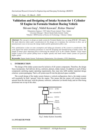
  • 1. International Research Journal in Engineering and Emerging Technology (IRJEET) Volume – 01, Issue – 01, March – 2020 www.we-irjeet.com 2019 IRJEET – All Right Reserved 1 | Page Validation and Designing of Intake System for 1 Cylinder SI Engine in Formula Student Racing Vehicle Shivam Garg1 , Nikhil Keswani2 , Rishav Sharma2 1 (Simulation Engineer / FEV India Private Limited / Pune / India) 2 (Assistant Manager / Maruti Suzuki India Limited / India) 3 (Student / SRM Institute of Science & Technology / Chennai / India) Abstract: The concept is to design an intake system for Formula Student race car using KTM RC 390 engine. The main objectives taken under consideration for the design are to minimize the restriction to flow, use of tuned pressure wave to increase the charge intake and the optimization of flow rate. Flow optimization is done on some assumption and taking gas dynamics of the system in consideration. This work support the initial calculation parameters to start the designing and manufacturing of intake system. The length of runner plays important form in delivering the amount of air in the cylinder chamber. Large runner length is good at low speeds (filling losses at higher speeds) and small runner intake systems are good for higher speeds. Keywords: Engine Intake System, Performance Optimization, Gas dynamics, CFD, Simulation 1. INTRODUCTION The design of the intake system must be inclusive of all system components. Therefore, the design focus incorporates: fuel delivery device, restrictor, plenum, intake runners. In addition to each of these components satisfying engine operating requirements, they must also fulfil another important design criterion: system packaging. That is, all system must fit into the physical space available. The overall design of the intake system features a vertical configuration; that is, the intake system will essentially be built ‘upward’ from the engine. This means that the runner will extend towards upward from the inlet port, with the plenum, restrictor, carburetor (or throttle body) and air filter being positioned one on top of the other. Fig 2. Intake System Assembly 1.1.INTAKE RUNNER
  • 2. International Research Journal in Engineering and Emerging Technology (IRJEET) Volume – 01, Issue – 01, March – 2020 www.we-irjeet.com 2019 IRJEET – All Right Reserved 2 | Page Intake runners perform a vital function by delivering intake charge to the cylinders. The design of these runners must therefore ensure that the mixture arrives in a highly combustible state, which inducing as few losses as possible throughout the mixture’s journey from carburetor to intake port. A number of factors must be considered to determine the overall runner design, including manifold type, runner dimensions and configuration. The inlet manifold will incorporate tuned. Achieving calculated length in a streamlined design will necessitate the inclusion of additional bends in the inner runner. The main objective to design the runner is to improve engine performance, with high-precision bending methods employed to minimize losses. Empirical formulae will dictate runner lengths for a desired tuned speed. However, the actual runner lengths will necessarily be a compromise between the desired tuning range and the space available. Bell (1997) recommends long-length pipes to tune for maximum torque at low to mid-range speeds. The recommendation is to use as long a length as possible within the allocated space. Smaller diameters have also been empirically found to increase torque and power in the low to mid-range. The configuration of the formula SAE completion track enables speed no greater than 100 km/hr., with average speeds of around 50-60 km/hr. therefore, engines used in this application required good low to mid-range torque. Long pipes and small diameters will therefore characterize intake manifold design, with specific dimensions to be determined by empirical formulae. 1.1.1. SHAPE AND LENGTH In order to provide as direct a path as possible, the orientation of the manifold runners is essentially dictated by the positioning of the central plenum and an inlet port. With the general orientation of the runners decided, determining the appropriate length for tuning at the desired speed now becomes the crucial aspect of the manifold design. Intake ramming is the desired effect of tuning intake runners. The pressure waves travelling through the intake system actually generate a number of reflected waves. That is, when the first reflected wave travels from the runner entrance and contacts the inlet valve, it generates another reflected wave, which is sent back towards the runner entrance. This generation continues again and again. Each successive reflected wave takes more time than the previous to arise and travel through the system; therefore, depending on the desired tuned speed, and taking the engine’s valve timing consideration, tuning for a certain pulse can be achieved. We can determine the tuned inlet length (in inches) for the third reflected pulse, (L) L = 97000 / n, here n is the desired tuned speed (rpm) Tuning for between 4000 and 8000 rpm is desired for AeroX Motorsports race car in Formula SAE Competition. Therefore, lower and upper length limits will be calculated, according to these two speeds. Lower Limit: Tuned speed = 8000 rpm L = 97000 / 8000 = 12.1 inches or 308 mm Upper Limit: Tuned speed = 4000 rpm L = 97000 / 4000 = 2403 inches or 616 mm If we go through the specification of the KTM RC 390 engine we can see, the engine is having 373.2 cc displacement with maximum power of 43 bhp @ 9500 rpm and maximum torque of 35 Nm @ 7250 rpm. Taking a compromise between two lengths 8000 rpm, 4000 rpm and also considering maximum torque at 7250 rpm, 7000 rpm produces a desired tuned length of: Tuned Inlet Length: Tuned Speed = 7000 rpm L = 97000 / 7000 = 13.85 inches or 351.97 mm Here, a tuned length of approximately 350 mm should provide increased charge volume and improved expulsion of exhaust gases at 7000 rpm. 1.2. INTAKE RESTRICTOR Formula SAE rules mandate the inclusion of a single, circular restrictor in the inlet system, no more than 20 mm in diameter (2016-17 Formula SAE Rules). This restrictor is required to be placed between
  • 3. International Research Journal in Engineering and Emerging Technology (IRJEET) Volume – 01, Issue – 01, March – 2020 www.we-irjeet.com 2019 IRJEET – All Right Reserved 3 | Page the throttle and the engine, with all airflow passing through this contraction, with the purpose of limiting engine power. The fluid dynamics largely governs design of the intake restrictor. A decreased flow area results in a reduced amount of charge flowing to the engine. Therefore, to extract maximum power from the engine, the restrictor must be designed to produce maximum flow through the 20 mm contraction. Restrictor design is governed by: specified dimensions (20mm diameter), flow characteristics, available space in intake system. Flow rate through the restrictor depends upon: entrance shape, exist shape, throat shape, length, surface finish and charge density (affected by pressure and temperature). Fig. Restrictor design 1.2.1. ENTRANCE, EXIT AND THROAT SHAPE Losses in pressure occur when flow travels through a sudden expansion or contraction in a pipe. However, losses due to change can be somewhat reduced by installing a nozzle or diffuser between the sections of interest (Fox & McDonald 2003). The restrictor must be placed between the throttle and engine, and have a maximum diameter of 20 mm. in this case, the carburetor (or throttle body for injected systems) will lead into the restrictor, which will then fellow on to the plenum. Therefore, a reduction in section from the specified 20 mm diameter to the diameter of the plenum opening is also required. Consequently, the most suitable shape for the restrictor becomes a conical converging diverging (nozzle-diffuser) arrangement. 1.2.2. ENTRANCE REGION DESIGN Table 1. Loss coefficients for gradual contractions: Round and Rectangular Ducts Area Ratio Included Angle, Ɵ (in Degree) A2 / A1 10 15-40 50-60 90 120 150 180 0.5 0.05 0.05 0.06 0.12 0.18 0.24 0.26 0.25 0.05 0.04 0.07 0.17 0.27 0.35 0.41 0.10 0.05 0.05 0.08 0.19 0.29 0.37 0.43 In case of constant area ratios (AR = A2 / A1), the nozzle length (the length between the two straight sections of pipe) then becomes critical: for constant AR, a shorter nozzle length requires a greater included angle, resulting in an increased loss coefficient K It is evident then, that to minimize losses through the restrictor entrance, a compromise must be taken between the length of the section and taper angle. The restrictor entrance region must provide for a reduction in section from the carburetor throat (40 mm) to the restrictor throat (20 mm). The AR is thus: A2 / A1 = 20 / 40 = 0.50 Using the minimum included angle provided (Ɵ = 10˚, means Ɵ/2 = 5˚), the length of the nozzle can be calculated as, Nozzle length, (LN) = 10 / tan (5) = 114.3 mm
  • 4. International Research Journal in Engineering and Emerging Technology (IRJEET) Volume – 01, Issue – 01, March – 2020 www.we-irjeet.com 2019 IRJEET – All Right Reserved 4 | Page It can however, be seen from table that the loss coefficient does not change appreciably for included angles between 10˚ and 40˚; consequently, it is conceivable that the taper angle could be increased from anywhere between 5˚ and 20˚ without resulting in any further loss in pressure. As the length that we calculated is quite large and we have to reduce it. We increases the angle from 10˚ to 20˚; now the length we got is, LN = 10 / tan (10) = 56.71 mm 1.2.3. DIFFUSER EXIT The intake restrictor has been allowed a maximum length of 150 mm, measured from the design of the vehicle having space in it. Entrance length is 56.71 mm, throat length taken can be 15 to 20 mm which results the exit length of 75 mm to 80 mm. Increase in radius (RDO), taking exit length of 75 mm RDO = 80 * tan (5) = 6.99 mm or 7 mm approximately. Diffuser outlet Diameter, DDO = (Throat diameter) + 2 RDO DDO = 20 + (2 * 7) = 34 mm 1.2.4. THROAT DESIGN Design parameters for the throat region dictate: maximum diameter of 20 mm and optimization of flow rate. Essentially, the throat must provide least restriction to flow by minimizing frictional losses. If the nozzle were to taper in to 20 mm and simply be joined to the diffuser at a point, a turbulent region would more than likely form at this point due to the sudden change in direction of flow. Therefore, the throat region, which provides the required 20 mm restriction, must be designed to minimize flow losses. Design of the throat region thus will incorporate a large bend radius, rounding into the minimum throat size of 20 mm, and leading back into the diffuser. Given that the geometries of the restrictor entrance and exit have been determined, and knowing that the minimum throat area will be 20 mm, a bend radius should be given so that the ratio of bend radius and 20 will be greater than 0.15 Because it can be said that any losses resulting from the ratio higher than 0.15 in section will be negligible. In our design we took D = 50, 50 / 20 = 2.5 which is greater than 0.15 and can be said that there is negligible losses in the section. 1.3. PLENUM DESIGN In automotive engineering, an inlet manifold or intake manifold is the part of an engine that supplies the fuel / air mixture to the cylinder. The plenum is a common volume from which intake runner extends. Intake charge flows from the carburetor (or throttle body) and accumulates in the plenum, creating a ‘reserve’ from which individual intake runners draw charge. Plenum is an intake manifold is designed such that it will provide enough amount of atomized air to the cylinder of engine and also to keep laminar air flow passing through it. Plenum volume is specific to each engine, with larger-capacity engines requiring larger plenum volume. Empirically, plenum volume and carburetor (or throttle body) throat size have been found to be inter-dependent, with smaller carburetors generally producing better performance when combined with larger plenums, and vice versa (Bell 1997). For our engine KTM RC 390 the volumetric displacement is 390 cc and the plenum designed should have 0.8 times of engine volumetric displacement in order to get good performance by engine.
  • 5. International Research Journal in Engineering and Emerging Technology (IRJEET) Volume – 01, Issue – 01, March – 2020 www.we-irjeet.com 2019 IRJEET – All Right Reserved 5 | Page Volume of plenum, (VP) = 0.8 times (displacement of engine) = 0.8 X 390 = 312 cc Fig 3. Internal section of intake system Creating a chamber in which inlet charge is able to accumulate provides a constant supply of charge in close proximity to the inlet runners. This reserve of charge provides additional momentum to the air / fuel flowing into the cylinder, creating a more efficient intake process, increasing inlet charge and hence providing greater power production. Fig 4. Intake system CAD design 1.4. BACK PRESSURE The ‘Back Pressure’ is often used in relation to intake systems and has an effect on engine power. Pressure is built up within the system due to the motion of atomized gases regularly pulsating from intake port. This back pressure resists the motion of gas flow, and is an undesirable quantity when chasing increased engine performance. Back pressure typically reduces engine power and should be minimized at all times. Enlarging intake runner pipes and using well designed runner reduces back pressure and helps to increase power. Atmospheric pressure (P1) = 101326.38 Pascal Inlet temperature (T1) = 300 K For air at 300 K, ϒ = 1.4; Cp = 1.005 KJ / Kg.K R = 287 KJ /Kg.K Speed of sound, C1 = (ϒRT1) 1/2 = 113.37 m/s Stagnation Temperature, To = T1 + (C1)2 / (2 Cp) = 306.3944 K T1 / To = 0.979 From gas table for isentropic gas flow at ϒ = 1.4, we get the value of Mach No. and other essential values. i.e.
  • 6. International Research Journal in Engineering and Emerging Technology (IRJEET) Volume – 01, Issue – 01, March – 2020 www.we-irjeet.com 2019 IRJEET – All Right Reserved 6 | Page P1 /Po = 1.00594; A1 / A*= 1.922 For an adiabatic irreversible process, (T1 / To) ϒ-1 / ϒ = (P1 /Po) Stagnation Pressure, Po = 101928.3194 Pascal Critical Area, A* = 3.14 X 0.2 X 0.2 / 1.922 = 0.0163 m2 Critical Pressure, P* = Po (2 / ϒ + 1) ϒ / ϒ-1 = 53818.15266 Pascal P* / Po = 0.588 Let back pressure acting on the system be Pb. There are 2 cases that can take place due to back pressure. i.e. P* / PO ≤ Pb / Po and, P* / PO ≥ Pb / Po If P* / PO ≤ Pb / Po equation is satisfying, m˚max (To R) 1/2 / A* PO (ϒ) 1/2 = (2 / ϒ+1) ϒ+1 / 2(ϒ-1) m˚max = 0.2805 Kg/s If P* / PO ≥ Pb / Po equation is satisfying, m˚max = ρ A2 C2 ρ = Pb / R T2 P* / PO ≥ Pb / Po or 0.588 ≥ Pb / Po For gas table at this pressure ration in isentropic gas flow at ϒ = 1.4. We get, Mach no (M) = 0.9; M* = 0.915; T2 / To = 0.861; A2 / A*= 1.009 T2 = 263.805 K and Pb = 59933.85 Pascal ρ = 0.7924 Kg / m3 C2 = (ϒRT2) 1/2 = 293.014 m/s m˚max = ρ A2 C2; A2 is at radius 0.017 m m˚max = 0.2108 Kg/s The calculated mass flow rate is the maximum amount of mass flow of air that can pass to the inlet port after having back pressure in the system. 1.5. RESONANCE FREQUENCY The design of resonator is characterized by the large cavity at its belly and a thin neck. It basically works on the theory of harmony. As the air tries to ram into the resonator through its neck, the pressure inside the cavity increases and the air bounces out, but while bouncing out quickly due to inertia, it creates a partial vacuum near the neck of the resonator and the air is again sucked in it. The process continues like the phenomenon of a Ping-Pong ball hitting the ground. The resonator acts like a shock absorber for the pressure waves. The frequency of a resonator can be calculated by (f) = (C/2π) (A/VL) 1/2 f = (113.37 / 2 X 3.141) (3.141 X 0.017 X 0.017 / 0.000312 X 0.350) 1/2 f = 1499.137 hz
  • 7. International Research Journal in Engineering and Emerging Technology (IRJEET) Volume – 01, Issue – 01, March – 2020 www.we-irjeet.com 2019 IRJEET – All Right Reserved 7 | Page Fig 5. Intake system assembled on race car CONCLUSIONS The overall manifold design has evolved through a series of preliminary designs, and should provide efficient flow and combustion, with improved fuel efficiency and increased power output. While compromises have been necessary in some aspects of this design, the overall design philosophy has been maintained, with the intake system designed in accordance with engineering principles and empirical data. The overall performance of the engine is increased and the results are good as compared to past results of the engine performance. REFERENCES [1] S. Das and J. K. Prasad. (2008). Characteristics of a supersonic Air-Intake with Bleed. Department of Space Engg. & Rocketry, B. I. T, Mesra, Ranchi, India. [2] P. Chudy, K. Fiakovsky, J. Friedl. (2004). Aerodynamic Analysis of turboprop Engine Air Intake. Czech Technical University Publishing House. [3] M. F. Harrison and P.T. Stanev. (2004) Measuring Wave Dynamics in I.C Engine Intake System. School of Engineering, Cranfield University, England. [4] M. Suzuki and C. Arakawa. (2002). Guide Vanes Effect of Wells Turbine for Wave Power Generator. Department Of Mechanical Engineering, University of Tokyo, Tokyo, Japan. [5] Par Nylander. (2008). CFD Modeling of Water Ingestion in Air Intake System. Lulea University of Technology.