
Recommended
More Related Content
What's hot
What's hot (19)
Similar to Kdl 40 v2500
Similar to Kdl 40 v2500 (20)
More from Mauricio Salgado
Recently uploaded
Recently uploaded (20)
Kdl 40 v2500
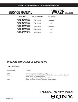
- 1. LCD DIGITAL COLOR TELEVISION SERVICE MANUAL WAX2FCHASSIS MODEL NAME REMOTE COMMANDER DESTINATION 9-883-722-03 KDL-40V2500 RM-YD012 CANADA KDL-40V2500 RM-YD012 US KDL-46V2500 RM-YD012 CANADA KDL-46V2500 RM-YD012 US KDL-46V25L1 RM-YD012 US HISTORY INFORMATION FOR THE FOLLOWING MANUAL: ORIGINAL MANUAL ISSUE DATE: 9/2006 ☛ :UPDATED ITEM REVISION DATE SUBJECT 9/2006 No revisions or updates are applicable at this time. 9/2006 Added APPENDIX A: ENCRYPTION KEY COMPONENTS to service manual. Added Page A-1 Updated Table of Contents. Replaced page 3 Updated Encryption Key notes. Replaced pages 23, 54-58, and 64 1/2007 Updated Block Diagram to show correct Boards. Replaced page 25.
- 2. LCD DIGITAL COLOR TELEVISION SERVICE MANUAL WAX2FCHASSIS MODEL NAME REMOTE COMMANDER DESTINATION 9-883-722-03 KDL-40V2500 RM-YD012 CANADA KDL-40V2500 RM-YD012 US KDL-46V2500 RM-YD012 CANADA KDL-46V2500 RM-YD012 US KDL-46V25L1 RM-YD012 US SelfDiagnosisSupported model KDL-40V2500 RM-YD012
- 3. 3KDL-40V2500/46V2500/46V25L1 KDL-40V2500/46V2500/46V25L1 TABLE OF CONTENTS SECTION TITLE PAGE SECTION TITLE PAGE Specifications ................................................................................. 4 Warnings and Cautions .................................................................. 6 Safety-Related Component Warning.............................................. 7 Safety Check-Out ........................................................................... 9 Self-Diagnostic Function............................................................... 10 SECTION 1: DISASSEMBLY............................................................... 12 1-1. Rear Cover Removal ............................................... 12 1-2. Vesa Bracket Assembly and Stand Removal........... 13 1-3. H1U Board Removal................................................ 14 1-4. G2A Board Removal................................................ 14 1-5. H2U Board Removal................................................ 15 1-6. AU Board Removal.................................................. 15 1-7. QT Board Removal.................................................. 16 1-8. H3U Board and Speaker Removal .......................... 16 1-9. QSF board and BU Board Removal ........................ 17 1-10. LCD Panel Removal ................................................ 18 SECTION 2: SERVICE ADJUSTMENTS............................................. 19 2-1. Remote Adjustment Buttons and Indicators......................... 19 2-2. Accessing Service Adjustments ........................................... 19 2-2-1. Accessing the Digital Service Adjustment Menus.... 19 2-2-2. Viewing the Digital Module Box (Q-Box) Service Items........................................................... 20 2-2-3. Accessing the Analog Service Adjustment Menus... 20 2-3. Resetting the User Menu - Factory Reset............................ 21 2-4. Aging Mode.......................................................................... 21 2-5. White Balance Adjustment. .................................................. 22 SECTION 3: DIAGRAMS..................................................................... 23 3-1. Circuit Boards Location........................................................ 23 3-2. Printed Wiring Boards and Schematic Diagrams Information......................................... 23 3-3. Block Diagram...................................................................... 25 3-4. Schematics and Supporting Information .............................. 26 AU Board Schematic Diagram (1 of 2)................................. 26 AU Board Schematic Diagram (2 of 2)................................. 27 BU Board Schematic Diagram (1 of 9)................................. 29 BU Board Schematic Diagram (2 of 9)................................. 30 BU Board Schematic Diagram (3 of 9)................................. 31 BU Board Schematic Diagram (4 of 9)................................. 32 BU Board Schematic Diagram (5 of 9)................................. 33 BU Board Schematic Diagram (6 of 9)................................. 34 BU Board Schematic Diagram (7 of 9)................................. 35 BU Board Schematic Diagram (8 of 9)................................. 36 BU Board Schematic Diagram (9 of 9)................................. 37 G2A Board Schematic Diagram ........................................... 39 H1U Board Schematic Diagram........................................... 41 H2U Board Schematic Diagram........................................... 42 H3U Board Schematic Diagram........................................... 44 QSF Board Schematic Diagram (1 of 5) .............................. 45 QSF Board Schematic Diagram (2 of 5) .............................. 46 QSF Board Schematic Diagram (3 of 5) .............................. 47 QSF Board Schematic Diagram (4 of 5) .............................. 48 QSF Board Schematic Diagram (5 of 5) .............................. 49 QT Board Schematic Diagram ............................................. 51 3-5. Semiconductors ................................................................... 53 SECTION 4: EXPLODED VIEWS........................................................ 54 4-1. Rear Cabinet and Stand Assembly ..................................... 54 4-2. Chassis ............................................................................... 55 4-3. Speakers.............................................................................. 56 4-4. LCD Panel............................................................................ 57 SECTION 5: ELECTRICAL PARTS LIST............................................ 58 APPENDIX A: ENCRYPTION KEY COMPONENTS..........................A-1
- 4. 4KDL-40V2500/46V2500/46V25L1 KDL-40V2500/46V2500/46V25L1 SPECIFICATIONS Design and specifications are subject to change without notice. 120V-240V AC, 50/60Hz 200W (KDL-40V2500 Only) 240W (KDL-46V2500/46V25L1 Only) Less than 0.1W Video (IN) 1/2/3: S Video (4-Pin Mini DIN (VIDEO 1/2 Only): Y: 1.0 Vp-p, 75 ohms unbalanced, sync negative C: 0.286 Vp-p (Burst signal), 75 ohms Video: 1.0 Vp-p, 75ohms unbalanced, sync negative Audio: 500 mVrms (100% modulation) Impedance:47 kilohms HD/DVD IN 4/5: YPB PR (Component Video): Y:1.0 Vp-p, 75 ohms unbalanced, sync negative PB :0.7 Vp-p, 75 ohms PR :0.7 Vp-p, 75 ohms Signal format: 480i, 480p, 720p, 1080i AUDIO: 500 mVrms (100% modulation) Impedance: 47 kilohms Power Requirements: Power Consumption (W): In Use (Max): In Standby : HDMI IN 6/7: HDMI: Video:480i, 480p, 720p, 1080i, 1080p Audio: Two channel linear PCM 32, 44.1 and 48 kHz, 16, 20 and 24 bits AUDIO (HDMI IN 6 Only): 500 mVrms (100% modulation) Impedance: 47 kilohms AUDIO OUT: 500 mVrms (100% modulation) More than 1 Vrms at the maximum volume setting (Variable) More than 500 mVrms (Fixed) PC IN 8: D-sub 15-pin, analog RGB, 0.7 Vp-p, 75 ohms, positive PC AUDIO INPUT: Stereo mini jack, 0.5 Vrms, 1 kilohm Headphones: Stereo mini jack Impedance: 16 ohms Speaker: Full range: 5.5 × 15 cmm (2 1/4 × 6 inches) (2) (KDL-40V2500) Full range: 7 × 13 cm (2 3/4 × 5 7/16 inches) (2) (KDL-46V2500/46V25L1) Trademark Information TruSurround XT, SRS and ( ) symbol are trademarks of SRS Labs, Inc. TruSurround XT technology is incorporated under license from SRS Labs, Inc. Manufactured under license from BBE Sound, Inc. Licensed by BBE Sound, Inc. under one or more of the following US patents: 5510752, 5736897. BBE and BBE symbol are registered trademarks of BBE Sound, Inc. Macintosh is a trademark licensed to Apple Computer, Inc., registered in the U.S.A and other countries. “BRAVIA” and are trademarks of Sony Corporation. As an ENERGY STAR® Partner, Sony Corporation has determined that this product meets the ENERGY STAR® guidelines for energy efficiency. ENERGY STAR® is a U.S. registered mark. This TV incorporates High-Definition Multimedia Interface (HDMI™) technology. HDMI, the HDMI logo and High-Definition Multimedia Interface are trademarks or registered trademarks of HDMI Licensing, LLC. Manufactured under license from Dolby Laboratories. “Dolby” and the double-D symbol are trademarks of Dolby Laboratories.
- 5. 5KDL-40V2500/46V2500/46V25L1 KDL-40V2500/46V2500/46V25L1 Television system American TV Standard ATSC compliant 8VSB ANSI/SCTE 07 2000 (Does not include CableCARD functionality) Channel coverage Analog Digital Terrestrial 2-69 2-69 Cable 1-125 1-135 Antenna 75-ohm external terminal for VHF/UHF Panel System LCD (Liquid Crystal Display) Panel Display Resolution (horizontal x vertical): 1,920 dots x 1,080 lines Screen Size (measured diagonally) 40 inches (KDL-40V2500 Only) 46 inches (KDL-46V2500/46V25L1 Only) Supplied Accessories Remote Commander RM-YD012 Two Size AA (R6) Batteries 75-ohm coaxial cable AC Power Cord HD15-HD15 Cable Suport Belt, Securing Screw, and Wood Screw Cable Holder Operating Instructions Quick Setup Guide Warranty Card Optional Accessories Headphones Plug Adaptor Connecting Cables Wall-Mount Bracket SU-WL51 .'/9 .'/9 .'/9/ 6SHDNHU 2XWSXW :
- 6. 'LPHQVLRQV : [ + [ '
- 7. ZLWK VWDQG PP [ [ PP [ [ PP LQ [ [ LQ [ [ LQ 'LPHQVLRQV : [ + [ '
- 8. ZLWKRXW VWDQG PP [ [ PP [ [ PP LQ [ [ LQ [ [ LQ 0DVV ZLWK VWDQG NJ NJ NJ OEV OEV R] OEV R] ZLWKRXW VWDQG NJ NJ NJ OEV OEV R] OEV R] : :
- 9. 6KDL-40V2500/46V2500/46V25L1 KDL-40V2500/46V2500/46V25L1 WARNINGS AND CAUTIONS CAUTION These servicing instructions are for use by qualified service personnel only. To reduce the risk of electric shock, do not perform any servicing other than that contained in the operating instructions unless you are qualified to do so. WARNING!! An isolation transformer should be used during any service to avoid possible shock hazard, because of live chassis. The chassis of this receiver is directly connected to the ac power line. ! SAFETY-RELATED COMPONENT WARNING!! Components identified by shading and ! mark on the schematic diagrams, exploded views, and in the parts list are critical for safe operation. Replace these components with Sony parts whose part numbers appear as shown in this manual or in supplements published by Sony. Circuit adjustments that are critical for safe operation are identified in this manual. Follow these procedures whenever critical components are replaced or improper operation is suspected. ATTENTION!! Ces instructions de service sont à l’usage du personnel de service qualifié seulement. Pour prévenir le risque de choc électrique, ne pas faire l’entretien autre que celui contenu dans le Mode d’emploi à moins que vous soyez qualifié faire ainsi. Afin d’eviter tout risque d’electrocution provenant d’un chássis sous tension, un transformateur d’isolement doit etre utilisé lors de tout dépannage. Le chássis de ce récepteur est directement raccordé à l’alimentation du secteur. ! ATTENTION AUX COMPOSANTS RELATIFS A LA SECURITE!! Les composants identifies par une trame et par une marque ! sur les schemas de principe, les vues explosees et les listes de pieces sont d’une importance critique pour la securite du fonctionnement. Ne les remplacer que par des composants Sony dont le numero de piece est indique dans le present manuel ou dans des supplements publies par Sony. Les reglages de circuit dont l’importance est critique pour la securite du fonctionnement sont identifies dans le present manuel. Suivre ces procedures lors de chaque remplacement de composants critiques, ou lorsqu’un mauvais fonctionnement suspecte.
- 10. 7KDL-40V2500/46V2500/46V25L1 KDL-40V2500/46V2500/46V25L1 SAFETY-RELATED COMPONENT WARNING There are critical components used in LCD color TVs that are important for safety. These components are identified with shading and ! mark on the schematic diagrams and the electrical parts list. It is essential that these critical parts be replaced only with the part number specified in the electrical parts list to prevent electric shock, fire, or other hazard. NOTE: Do not modify the original design without obtaining written permission from the manufacturer or you will void the original parts and labor guarantee. USE CAUTION WHEN HANDLING THE LCD PANEL When repairing the LCD panel, be sure you are grounded by using a wrist band. When installing the LCD panel on a wall, the LCD panel must be secured using the 4 mounting holes on the rear cover. To avoid damaging the LCD panel: do not press on the panel or frame edge to avoid the risk of electric shock. do not scratch or press on the panel with any sharp objects. do not leave the module in high temperatures or in areas of high humidity for an extended period of time. do not expose the LCD panel to direct sunlight. avoid contact with water. It may cause a short circuit within the module. disconnect the AC adapter when replacing the backlight (CCFL) or inverter circuit. (High voltage occurs at the inverter circuit at 650Vrms.) always clean the LCD panel with a soft cloth material. use care when handling the wires or connectors of the inverter circuit. Damaging the wires may cause a short. protect the panel from ESD to avoid damaging the electronic circuit (C-MOS). LEAKAGE CURRENT HOT CHECK CIRCUIT
- 11. 8KDL-40V2500/46V2500/46V25L1 KDL-40V2500/46V2500/46V25L1 The circuit boards used in these models have been processed using Lead Free Solder. The boards are identified by the LF logo located close to the board designation e.g. H1 etc [ see example ]. The servicing of these boards requires special precautions to be taken as outlined below. example 1 It is strongly recommended to use Lead Free Solder material in order to guarantee optimal quality of new solder joints. Lead Free Solder is available under the following part numbers : Due to the higher melting point of Lead Free Solder the soldering iron tip temperature needs to be set to 370 degrees centigrade. This requires soldering equipment capable of accurate temperature control coupled with a good heat recovery characteristics. For more information on the use of Lead Free Solder, please refer to http://www.sony-training.com rebmuntraP retemaiD skrameR 91-500-046-7 mm3.0 gK52.0 02-500-046-7 mm4.0 gK05.0 12-500-046-7 mm5.0 gK05.0 22-500-046-7 mm6.0 gK52.0 32-500-046-7 mm8.0 gK00.1 42-500-046-7 mm0.1 gK00.1 52-500-046-7 mm2.1 gK00.1 62-500-046-7 mm6.1 gK00.1
- 12. 9KDL-40V2500/46V2500/46V25L1 KDL-40V2500/46V2500/46V25L1 SAFETY CHECK-OUT After correcting the original service problem, perform the following safety checks before releasing the set to the customer: 1. Check the area of your repair for unsoldered or poorly soldered connections. Check the entire board surface for solder splashes and bridges. 2. Check the interboard wiring to ensure that no wires are “pinched” or touching high-wattage resistors. 3. Check that all control knobs, shields, covers, ground straps, and mounting hardware have been replaced. Be absolutely certain that you have replaced all the insulators. 4. Look for unauthorized replacement parts, particularly transistors, that were installed during a previous repair. Point them out to the customer and recommend their replacement. 5. Look for parts which, though functioning, show obvious signs of deterioration. Point them out to the customer and recommend their replacement. 6. Check the line cords for cracks and abrasion. Recommend the replacement of any such line cord to the customer. 7. Check the antenna terminals, metal trim, “metallized” knobs, screws, and all other exposed metal parts for AC leakage. Check leakage as described below. Leakage Test The AC leakage from any exposed metal part to earth ground and from all exposed metal parts to any exposed metal part having a return to chassis, must not exceed 0.5 mA (500 microamperes). Leakage current can be measured by any one of three methods. 1. A commercial leakage tester, such as the Simpson 229 or RCA WT-540A. Follow the manufacturers’ instructions to use these instructions. 2. A battery-operated AC milliampmeter. The Data Precision 245 digital multimeter is suitable for this job. 3. Measuring the voltage drop across a resistor by means of a VOM or battery-operated AC voltmeter. The “limit” indication is 0.75 V, so analog meters must have an accurate low voltage scale. The Simpson’s 250 and Sanwa SH-63TRD are examples of passive VOMs that are suitable. Nearly all battery-operated digital multimeters that have a 2 VAC range are suitable (see Figure A). How to Find a Good Earth Ground A cold-water pipe is a guaranteed earth ground; the cover-plate retaining screw on most AC outlet boxes is also at earth ground. If the retaining screw is to be used as your earth ground, verify that it is at ground by measuring the resistance between it and a cold-water pipe with an ohmmeter. The reading should be zero ohms. If a cold-water pipe is not accessible, connect a 60- to 100-watt trouble- light (not a neon lamp) between the hot side of the receptacle and the retaining screw. Try both slots, if necessary, to locate the hot side on the line; the lamp should light at normal brilliance if the screw is at ground potential (see Figure B). To Exposed Metal Parts on Set 0.15 µF Earth Ground AC Voltmeter (0.75V) Trouble Light AC Outlet Box Ohmmeter Cold-water Pipe Figure A. Using an AC voltmeter to check AC leakage. Figure B. Checking for earth ground.
- 13. 10KDL-40V2500/46V2500/46V25L1 KDL-40V2500/46V2500/46V25L1 SELF-DIAGNOSTIC FUNCTION SelfDiagnosisSupported model Control Buttons PIC OFF/TIMER STANDBY POWER TV/VIDEO VOLUME MENU CHANNEL POWER Description of LED Indictors LED LED Type Description * Light is green when the TV set is on * Functions as failure indicator * Blinks green in aging mode TIMER LED Red LED Lights when timer is set PIC OFF LED Green LED Lights when power saving setting is set to picture off (See Instruction Manual) POWER LED Red/Green LED
- 14. 11KDL-40V2500/46V2500/46V25L1 KDL-40V2500/46V2500/46V25L1 LED Control 3RZHU 2II 2II 2II 2II 3RZHU RII XVLQJ WKH SRZHU VZLWFK RU UHPRWH FRQWURO 127( 6WDQGE VWDWH GRHV QRW H[LVW LQ WKLV PRGHO KRZHYHU WKH PLFURFRPSXWHU GRHV HQWHU LQWR VOHHS PRGH 3RZHU 2II /LJKWV *UHHQ 2II 2II 0LFURFRPSXWHU ZRUNLQJ QRUPDOO )DLOXUH %OLQNV 5HG 2II 2II )DLOXUH FDXVHV DUH FODVVLILHG E WKH QXPEHU RI WLPH WKH UHG OLJKW EOLQNV $JLQJ %OLQNV *UHHQ 2II 2II $JLQJ PRGH LV FODVVLILHG E D EOLQNLQJ JUHHQ OLJKW 3LFWXUH 2II /LJKWV *UHHQ /LJKWV *UHHQ 2II 1R GLVSOD EODFN VFUHHQ
- 15. /LJKWV *UHHQ /LJKWV 2UDQJH 2II :KHQ 6/((3 7,0(5 LV VHW GXULQJ SRZHU RQ /LJKWV *UHHQ /LJKWV *UHHQ 2II :KHQ 6/((3 7,0(5 LV VHW LQ 3LFWXUH 2II PRGH 2II /LJKWV 2UDQJH 2II :KHQ 21 7,0(5 LV VHW DQG SRZHU LV RII /LJKWV *UHHQ /LJKWV 2UDQJH 2II :KHQ 21 7,0(5 LV VHW DQG SRZHU LV RQ /LJKWV *UHHQ /LJKWV *UHHQ 2II :KHQ 21 7,0(5 LV VHW LQ 3LFWXUH 2II PRGH 3 67$1'% 2II 2II /LJKWV 5HG 3 67$1'% 7,0(5 21 2II /LJKWV 2UDQJH /LJKWV 5HG 5(0$5.667$1'% /(' 7,0(5 /(' 3,785( 2)) /(' 6/((3 7,0(5 21 7,0(5 67$786 32:(5 /(' The units in this manual contain a self-diagnostic function. If an error occurs, the POWER LED will automatically begin to flash. The number of times the LED flashes translates to a probable source of the problem. A definition of the POWER LED flash indicators is listed in the instruction manual for the user’s knowledge and reference. If an error symptom is difficult to reproduced use the Remote Commander to display the record that is stored at the internal NVM to specify the cause of the failure. Diagnostic Test Indicators When an error occurs, the POWER LED will flash a set number of times to indicate the possible cause of the problem. If there is more than one error, the LED will identify the first of the problem areas. If the errors occur simultaneously, the one that corresponds to the fewest flashes is identified first. Results for all of the following diagnostic items are displayed on screen. No error has occurred if the screen displays a “0”. 1XPEHU RI 7LPHV 32:(5 /(' %OLQNV 0RQLWRULQJ ,WHP 7LPH $EQRUPDO $8 3RZHU 9ROWDJH '$/(57
- 16. 7LPHV $EQRUPDO '9$9 3RZHU 9ROWDJH '$/(57
- 17. 7LPHV $EQRUPDO 3DQHO 9ROWDJH '$/(57
- 18. 7LPHV %DFNOLJKW )DLOXUH 7LPHV $EQRUPDO 0DLQ 3RZHU 9ROWDJH 7LPHV $EQRUPDO 6SHDNHU 9ROWDJH 7LPHV ,QWHUQDO 7HPSHUDWXUH 5LVH PDLQO RQ WKH SDQHO VLGH
- 19. 7LPHV ,
- 20. 12KDL-40V2500/46V2500/46V25L1 KDL-40V2500/46V2500/46V25L1 SECTION 1: DISASSEMBLY 1-1. REAR COVER REMOVAL Rear Cover 12 Screws, +BVTP2 4X16 (KDL-40V2500 ONLY) 4 Screws, +PSW M6X16 18 Screws, +BVTP2 4X16 (KDL-46V2500/46V25L1) 5 Screws, +BVPT 3X12 TYPE2 IT-3 2 1 4 5 Screws, +PSW M3X53
- 21. 13KDL-40V2500/46V2500/46V25L1 KDL-40V2500/46V2500/46V25L1 Stand Assembly VESA Bracket Assembly 2 4 Screws, +PSW M5X16 1 4 Screws, +PSW M4X16 1-2. VESA BRACKET ASSEMBLY AND STAND REMOVAL
- 22. 14KDL-40V2500/46V2500/46V25L1 KDL-40V2500/46V2500/46V25L1 1-3. H1U BOARD REMOVAL 1-4. G2A BOARD REMOVAL 1 2 Screws, +BVTP2 4X16 Multi Button Assy Disconnect CN1101 H1U Board 4 Screws, +PSW 3SG 1 G2 Bracket G2A board 4 Connectors CN6001, CN6200, CN6202 and CN6217
- 23. 15KDL-40V2500/46V2500/46V25L1 KDL-40V2500/46V2500/46V25L1 1-5. H2U BOARD REMOVAL H2U Board Side Jack Holder Side Terminal Assembly 2 Screws, +BVTP 3X12 TYPE2 IT-3 One Connector CN1201 1 AU board 1 6 Screws, +BVST 3x8 Disconnect CN9501, CN9502, CN9001, CN2500, CN2303, CN2302 and CN2301 1-6. AU BOARD REMOVAL
- 24. 16KDL-40V2500/46V2500/46V25L1 KDL-40V2500/46V2500/46V25L1 1-7. QT BOARD REMOVAL 1-8. H3U BOARD AND SPEAKER REMOVAL 1 One Screw, +PSW M3x5 2 4 Screws, +BVST 3x8 QT Board 3 2 Screws, +BVTP2 4X16 4 2 Screws, +KTT 3X10 2 2 Screws, +BVTP2 4X16 1 4 Screws, +PSW M5X8 H3U Board Bottom Frame Assembly AC Inlet Speaker Speaker Under Cover 5 One Screw, +PSW M4X8
- 25. 17KDL-40V2500/46V2500/46V25L1 KDL-40V2500/46V2500/46V25L1 2 7 Screws, +BVST 3X8 4 3 Screws, +PSW M3X5 1 4 Screws, +BVST 3X8 3 9 Screws, +PSW M3X5 Chassis Bracket QSF Board BU Board Disconnect CN4001, CN4002, CN4007, CN4008, CN4701, CN4702, CN4300, CN5003, CN7003 and CN7008 Disconnect CN7314, CN7317 and CN7802 1-9. QSF BOARD AND BU BOARD REMOVAL
- 26. 18KDL-40V2500/46V2500/46V25L1 KDL-40V2500/46V2500/46V25L1 1-10. LCD PANEL REMOVAL 2 Top Frame Bezel Assembly LCD Panel Harness with Connector (LVDS) Bezel Support (S) (46” Panel only) Bezel Support (L) (46” Panel only) Panel Corner Bracket Two Screws, +BVTP2 4X16 3 Two Screws, +BVTP 3X12 1 Two Screws, +BVTP2 4X16 4 Two Screws, +PSW 5X8 5 Two Screws, +BVTP2 4X12
- 27. 19KDL-40V2500/46V2500/46V25L1 KDL-40V2500/46V2500/46V25L1 2-1. REMOTE ADJUSTMENT BUTTONS AND INDICATORS POWER DIGITAL/ ANALOG Onscreen cursor and select button DISPLAY RM-YD012 5 VOLUME+ SECTION 2: SERVICE ADJUSTMENTS 2-2. ACCESSING SERVICE ADJUSTMENTS To adjust various set features, use the Remote Commander to put the set into service mode to display the service menus. The Remote Commander displays the service menu associated with the Digital or Analog format depending on which format is on the TV when you enter service mode. 2-2-1. ACCESSING THE DIGITAL SERVICE ADJUSTMENT MENUS 1. Turn the TV on and view a Digital channel. 2. Put the TV in standby mode. (Power off). 3. Press the following buttons on the Remote Commander within a second: DISPLAY Channel 5 Volume + POWER On. The Digital service menu displays. Video 1 MAIN VER. 1009 H PACK VER. 1008 S PACK VER. 1008 CHECK SUM E20E NVM VER. 1006 ATI VER. 01.06 ATI UD NVM VER. 02 ATI SD NVM VER. 02 ETI 46h 39m 4. Use the button to view the next category listing the white balance adjustment items. Video 1 R_DRIVE 256 B_DRIVE 256 R_BKG 512 G_BKG 512 B_BKG 512 COLOR SAVE 5. Use the or button to select the item you want to adjust. a. To increase the data value of the category, press the button. b. To decrease the data value of the category, press the button. 6. To save the data value changes, press the button to select Color Save and then press the button. a. To save the data value changes, select Save by pressing the button and then press the button. b. To cancel the data value changes, select Cancel by pressing the button and then pressing the button.
- 28. 20KDL-40V2500/46V2500/46V25L1 KDL-40V2500/46V2500/46V25L1 2-2-2. VIEWING THE DIGITAL MODULE BOX (Q-BOX) SERVICE ITEMS Use the following instructions to display the Digital menu items you want to adjust. 1. Turn the TV on and view a Digital channel. 2. Put the TV in standby mode. (Power off). 3. Press the following buttons on the Remote Commander within a second: DISPLAY Channel 5 Volume + POWER On. The Digital service menu displays. Video 1 MAIN VER. 1009 H PACK VER. 1008 S PACK VER. 1008 CHECK SUM E20E NVM VER. 1006 ATI VER. 01.06 ATI UD NVM VER. 02 ATI SD NVM VER. 02 ETI 46h 39m 4. To display the Digital Module (Q Box) service adjustment menus, press JUMP . The QM category displays. Category Item SERVICE DTVINFO QM Item # Data Value Sample DMB (Q Box) Service Menu 0 0 5. To change the category, press 2 or 5 on the Remote Commander. Note: Pressing 2 or 5 only changes the categories within the service menu displayed. To return to the Digital Service Menu, press the JUMP button. 6. To change the adjustment item, press 1 or 4 on the Remote Commander. 7. To change the data value, press 3 or 6 on the Remote Commander. Note: To go back to the last saved data value, press 0 then ENTER on the Remote Commander to read the memory. 8. To write into memory, press MUTING then ENT on the Remote Commander. 9. To exit service mode, turn the power off. 2-2-3. ACCESSING THE ANALOG SERVICE ADJUSTMENT MENUS 1. Turn the TV on and view an Analog channel. 2. Put the TV in standby mode. (Power off). 3. Press the following buttons on the Remote Commander within a second: DISPLAY Channel 5 Volume + POWER On. The Analog service menu displays. Video 1 MAIN VER. 1008 H PACK VER. 1005 S PACK VER. 1008 CHECK SUM F99F NVM VER. 1006 ATI VER. ATI UD NVM VER. ATI SD NVM VER. 02 ETI 2h 16m 4. Use the button to view the next category listing the white balance adjustment items. Video 1 R_DRIVE 256 B_DRIVE 256 R_BKG 512 G_BKG 512 B_BKG 512 COLOR SAVE 5. Use the or button to select the item you want to adjust. a. To increase the data value of the category, press the button. b. To decrease the data value of the category, press the button. 6. To save the data value changes, press the button to select Color Save and then press the button. a. To save the data value changes, select Save by pressing the button and then press the button. b. To cancel the data value changes, select Cancel by pressing the button and then pressing the button.
- 29. 21KDL-40V2500/46V2500/46V25L1 KDL-40V2500/46V2500/46V25L1 2-3. RESETTING THE USER MENU - FACTORY RESET The TEST RESET option resets all the customer adjustable data back to the factory defaults. 1. Put the TV in standby mode. (Power off). 2. Press the following buttons on the Remote Commander within a second: DISPLAY Channel 5 Volume + POWER On. The service menu displays. 2-4. AGING MODE Aging mode is designed to remove image retention from the screen. NOTE: Once you enter into Aging Mode the Remote Commander no longer functions with the set. To turn off the set, push the Power Button on the set. 1. Put the TV in standby mode. (Power off). 2. Press the following buttons on the Remote Commander within a second: DISPLAY Channel 5 Volume + POWER On. The service menu displays. Video 1 MAIN VER. 1009 H PACK VER. 1008 S PACK VER. 1008 CHECK SUM E20E NVM VER. 1006 ATI VER. 01.06 ATI UD NVM VER. 02 ATI SD NVM VER. 02 ETI 46h 39m 3. Use the button to view the next category listing the white balance adjustment items. Video 1 R_DRIVE 256 B_DRIVE 256 R_BKG 512 G_BKG 512 B_BKG 512 COLOR SAVE 4. Continue pressing the button until the next category list displays. Video 1 TEST RESET AGING MODE Off AUTO SHUT-OFF On ETI CLEAR INFORMATION RESET SOUND MUTE On 5. Press the button to select AGING MODE. 6. Press the button to display the Aging Mode options. 7. Press the button to select ON. 8. Press the button to start the aging process. Video 1 MAIN VER. 1009 H PACK VER. 1008 S PACK VER. 1008 CHECK SUM E20E NVM VER. 1006 ATI VER. 01.06 ATI UD NVM VER. 02 ATI SD NVM VER. 02 ETI 46h 39m 3. Use the button to view the next category listing the white balance adjustment items. Video 1 R_DRIVE 256 B_DRIVE 256 R_BKG 512 G_BKG 512 B_BKG 512 COLOR SAVE 4. Continue pressing the button until the next category list displays. Video 1 TEST RESET AGING MODE Off AUTO SHUT-OFF On ETI CLEAR INFORMATION RESET SOUND MUTE On 5. Press the button to select TEST RESET options. 6. Press the button to select OK. 7. Press the button to reset the TV.
- 30. 22KDL-40V2500/46V2500/46V25L1 KDL-40V2500/46V2500/46V25L1 2-5. WHITE BALANCE ADJUSTMENT. The White Balance only needs to be adjusted when you replace the BU Board. 1. Through the Video 1 input, step Gray Scale with Setup. 2. Press MENU on the Remote Commander. The User Menu displays. Select from connected equipment MENU External Inputs Analog Favorites Digital Favorites Analog Digital Settings Select: Exit:Set: MENU 3. Press the button until Settings is selected, then press the button. 4. From the Picture menu, press the button to display the picture mode options. a. Press the button to select Custom, then press the button. 5. From the Picture menu, press the button to select Color Temperature. a. Press the button to display the Color Temperature options. b. Press the button to select Cool, then press the button. 6. From the Picture menu, press the button to select Advanced Settings. Picture Video 1 Target Inputs All Inputs Picture Mode Custom Reset Backlight Max Picture Max Brightness 50 Color 50 Hue 0 Color Temperature Cool Sharpness 15 Noise Reduction Low Advanced Settings AA DD Select: Back: Exit:Set: MENURETURN 7. Using the arrow keys set all the registers in the Advanced Setting menu to Off. Picture Video 1 Advanced Settings Reset Black Corrector Off Contrast Enhancer Off Gamma Off Clear White Off Live Color Off MPEG Noise Reduction Off AA DD Select: Back: Exit:Set: MENURETURN 8. Put the TV in standby mode. (Power off). 9. Access the Service Menu by pressing the following buttons on the Remote Commander within a second: DISPLAY Channel 5 Volume + POWER On. The Digital service menu displays. Video 1 MAIN VER. 1009 H PACK VER. 1008 S PACK VER. 1008 CHECK SUM E20E NVM VER. 1006 ATI VER. 01.06 ATI UD NVM VER. 02 ATI SD NVM VER. 02 ETI 46h 39m 10.Press the button to display the white balance adjustment menu items. Video 1 R_DRIVE 256 B_DRIVE 256 R_BKG 512 G_BKG 512 B_BKG 512 COLOR SAVE 11.Using 10 step NTSC Gray Scale with Setup adjust the White Balance of the 60% shade with R_Drive and B_Drive. 12.Using the same pattern, adjust the white balance 20% with R_BKG and B_BKG. 13.20IRE and 60IRE shades should have the same color. 20 IRE Level 60 IRE Level 20% 188mv 60% 451mv SET-UP 56mv 10 STEP GRAY SCALE
- 31. 23 KDL-40V2500/46V2500/46V25L1 KDL-40V2500/46V2500/46V25L1 SECTION 3: DIAGRAMS 3-1. CIRCUIT BOARDS LOCATION H3U Board AU Board H2U Board H1U Board BU Board G2A Board QSF Board QT Board 3-2. PRINTED WIRING BOARDS AND SCHEMATIC DIAGRAMS INFORMATION All capacitors are in µF unless otherwise noted. pF : µµF 50WV or less are not indicated except for electrolytics and tantalums. All electrolytics are in 50V unless otherwise specified. All resistors are in ohms. kΩ=1000Ω, MΩ=1000kΩ Indication of resistance, which does not have one for rating electrical power, is as follows: Pitch : 5mm Rating electrical power : 1 /4 W 1 /4 W in resistance, 1 /10 W and 1 /16 W in chip resistance. : nonflammable resistor : fusible resistor : internal component : panel designation and adjustment for repair : earth ground : earth-chassis All variable and adjustable resistors have characteristic curve B, unless otherwise noted. Readings are taken with a color-bar signal input. Readings are taken with a 10MΩ digital multimeter. Voltages are DC with respect to ground unless otherwise noted. Voltage variations may be noted due to normal production tolerances. All voltages are in V. S : Measurement impossibility. : B+line. : B-line. (Actual measured value may be different). : signal path. (RF) Circled numbers are waveform references. The components identified by shading and ! symbol are critical for safety. Replace only with part number specified. The symbol indicates a fast operating fuse and is displayed on the component side of the board. Replace only with fuse of the same rating as marked. Les composants identifies per un trame et une marque ! sont critiques pour la securite. Ne les remplacer que par une piece portant le numero specifie. Le symbole indique une fusible a action rapide. Doit etre remplace par une fusible de meme yaleur, comme maque. NOTE: The components identified by a red outline and a mark contain confidential information. Specific instructions must be adhered to whenever these components are repaired and/or replaced. See Appendix A: Encryption Key Components in the back of this manual.
- 32. 24 KDL-40V2500/46V2500/46V25L1 KDL-40V2500/46V2500/46V25L1 G D S B1 E1C2 B2 C1E2 2 3 4 5 6 7 8 9 0 !¡ !™ !¢ !§ !¶ !• – 1 G D S B2 E2C1 B1 C2E1 B2 E2C1 B1 C2E1 B2 E2C1 B1 C2E1 !ª B1 E1E2 C1(B2)C2 @º B1E2 C1C2 @™ @£ (B2) E1 (B2) E1 E2B1 C2C1 @¡ B1 E1 C2 B2 C1 E2 G S S D G D B1 E1 C2 B2 C1 E2 B1 E2 C2C1(B2) E2 B1 C1 C2E1(B2) C2 B1 C1 E2E1(B2) C2 B1 C1 E2 B2 E1 C2 Ver.1.6 Transistor (FET) Transistor Transistor Transistor Transistor Transistor Transistor Transistor Transistor Transistor Discrete semiconductot (Chip semiconductors that are not actually used are included.) Diode Diode Diode Diode Diode Diode Diode Diode Diode Diode Source Source Anode Anode (NC) (NC) Cathode Anode Cathode Common Cathode Cathode Common Cathode Cathode Common Common Common Common Cathode Anode Base Emitter Collector Base Emitter Collector Drain Gate Gate Drain Device Printed symbol Terminal name Circuit Terminal name of semiconductors in silk screen printed circuit ( ) Anode Anode Anode Cathode Anode Anode Cathode !£ Transistor (FET) Transistor (FET) !? Emitter Collector Base Transistor Source Gate Drain Cathode Anode Anode Cathode Anode Anode * REFERENCE INFORMATION RESISTOR : RN METAL FILM : RC SOLID : FPRD NONFLAMMABLE CARBON : FUSE NONFLAMMABLE FUSIBLE : RW NONFLAMMABLE WIREWOUND : RS NONFLAMMABLE METAL OXIDE : RB NONFLAMMABLE CEMENT : ADJUSTMENT RESISTOR COIL : LF-8L MICRO INDUCTOR CAPACITOR : TA TANTALUM : PS STYROL : PP POLYPROPYLENE : PT MYLAR : MPS METALIZED POLYESTER : MPP METALIZED POLYPROPYLENE : ALB BIPOLAR : ALT HIGH TEMPERATURE : ALR HIGH RIPPLE
- 33. 25 KDL-40V2500/46V2500/46V25L1 KDL-40V2500/46V2500/46V25L1 3-3. BLOCK DIAGRAM 2007/1/22 Analog-Component/RGB Y/C CVBS+Y/C Digital-Component Audio (Analog) Audio (Digital) CVBS PC-RGB Audio SW CD4052 Digital F/E BU RF Hs/Vs D-Comp[15:0] UFEUFE Audio for DVI CLK/Hs/Vs Auto Wide CXD2057M Main Micro MB91305 EEP Flash 2MByte TMDS I2C 8bit Multiplex BUS HDMI 16bit BUS SPDIF Cable PC I2C Optical Audio Out SWSW I2S Comp1 AV SW CXA2069Q Comp2 (S)Video1 (S)Video2 Video3 Audio out (Fix/Var.) PanelᯘFHDᯙ Backlight Inverter AV mouse Audio Amp. HP Amp.HP Amp. MAP4400A D/A MPEG DEC.MPEG DEC. CPUCPU ATiATi x240Hx240H I2C IF QT QSF D/AD/A AU/H Chroma Dec/IP /Scalar Trident SVP-LXS Audio for PC HDMI UART Jig(ECS) HDMI-Rx SiI9023 I2S DDR1 4M x 32bit DDR1 4M x 32bit I2C I2C RTC UART ☛
- 34. KDL-40V2500/46V2500/46V25L1 KDL-40V2500/46V2500/46V25L1 26 1 | 2 | 3 | 4 | 5 | 6 | 7 | 8 | 9 | 10 | 11 | 12 | 13 | 14 | 15 | 16 | 17 | 18 | 19 | 20 | 21 | 22 | A — B — C — D — E — F — G — H — I — J — K — L — M — N — O — P AU BOARD SCHEMATIC DIAGRAM (1 OF 2) 3-4. SCHEMATICS AND SUPPORTING INFORMATION D1_IN_AU_L,D1_IN_AU_R D2_IN_AU_L,D2_IN_AU_R 2012 16V 1 B C9006 CHIP 0 R9013 1/10W RN-CP 470k R9004 CHIP 0 R9012 2012 16V 1 B C9007 2012 16V 1 B C9008 CHIP 0 R9010 1/10W RN-CP 470k R9005 1/10W RN-CP 220k R9088 CHIP 0 R9011 1/10W RN-CP 220k R9089 1/10W RN-CP 470k R9007 2012 16V 1 B C9005 D1_IN_CB,D1_IN_CR,D1_IN_Y D2_IN_CB,D2_IN_CR,D2_IN_Y D3.3V 16V 100 C2015 V2_IN_AU_L,V2_IN_AU_R 16V 10 C2019 D1_IN_AU_L,D1_IN_AU_R 2012 16V 1 B C2017 V2_IN_C,V2_IN_S2SW,V2_IN_SSW,V2_IN_V,V2_IN_Y V1_IN_AU_L,V1_IN_AU_R V3_IN_AU_L,V3_IN_AU_R V1_IN_C,V1_IN_S2SW,V1_IN_SSW,V1_IN_V,V1_IN_Y 2012 16V 1 B C2016 22uH L2002 1608 16V 0.22 B C2020 D2_IN_AU_L,D2_IN_AU_R 1/10W RN-CP 22 R9038 1/10W RN-CP 22 R9043 1/10W RN-CP 22 R9044 1/10W RN-CP 22 R9034 1/10W RN-CP 22 R9036 1/10W RN-CP 22 R9037 CHIP 0 R2017 A9V GRN BLU RED WHT RED GRN BLU RED WHT RED J9002 1 2 3 4 5 6 7 8 9 10 11 12 13 14 15 16 17 18 19 20 CHIP 0 R9023 1/10W RN-CP 100 R9078 2012 10V 2.2 B C9020 2012 10V 2.2 B C9019 2012 10V 2.2 B C9021 1/10W RN-CP 100 R9057 1/10W RN-CP 470k R9020 1/10W RN-CP 100 R9061 1/10W RN-CP 75 R9039 5% 1/10W RN-CP 1k R90601608 10V 0.47 B C9016 2012 10V 2.2 B C9022 2012 16V 1 B C9023 2012 16V 1 B C9015 2012 16V 1 B C9024 2012 16V 1 B C9014 V3_IN_AU_L,V3_IN_AU_R 1608 CHIP R9045 0 1/10W RN-CP 1k R9059 1/10W RN-CP 470k R9021 CHIP 0 R9031 1/10W RN-CP 100 R9058 V1_IN_AU_L,V1_IN_AU_R CHIP 0 R9030 CHIP 0 R9024 1608 CHIP R9046 0 1/10W RN-CP R9022 470k 1/10W RN-CP 470k R9019 3 4 1 2 J9001 1 2 3 4 5 6 7 8 9 10 11 13 12 14 15 16 17 18 19 20 V1_IN_C,V1_IN_S2SW,V1_IN_SSW,V1_IN_V,V1_IN_Y 1/10W RN-CP 470k R9006 1608 50V 4700p B C2114 2SC3052EF-T1-LEF Q2109 1/10W RN-CP 5% 4.7k R2121 1608 16V 0.1 B C2101 2012 6.3V 4.7 B C2122 10uH L2101 1608 CHIP R2140 0 1608 16V 0.22 B C2120 1/10W RN-CP 5% 1k R2137 2SA1235TP-1EF Q2102 2SA1235TP-1EF Q2104 1/10W RN-CP 5% 4.7k R2109 RB501V-40TE-17 D2101 16V 100 C2103 1/10W RN-CP 5% 1M R2117 1608 50V 2200p B C2119 2SA1235TP-1EF Q2101 2SC3052EF-T1-LEF Q2108 1608 25V 0.022 B C2105 1/10W RN-CP 5% 1M R2132 1/10W RN-CP 5% 2.2k R2101 1608 16V 0.1 B C2111 1/10W RN-CP 0.5% 2.7k R2125 1/10W RN-CP 0.5% 3.9k R2128 A9V VD9025 VD9026 1/10W RN-CP 1k R9095 1/10W RN-CP 1k R9096 1/10W RN-CP 1k R9097 1/10W RN-CP 1k R9098 1/10W RN-CP 1k R9099 1/10W RN-CP 1k R9100 1/10W RN-CP 1k R9101 1/10W RN-CP 1k R9102 D3.3V D5V 1 2 3 4 5 6 7 8 9 9P CN9502 A9V GND D5V D3.3V GND GND Hsync_AU Vsync_AU GND V2_IN_AU_L,V2_IN_AU_R 1 2 3 4 5 6 7 8 9 10 11 12 13 14 15 15P CN9001 HP_DET HP_OUT_AU_L AU_IN_GND HP_OUT_AU_R V2_IN_SSW V2_IN_S2SW V2_IN_AU_R AU_IN_GND V2_IN_AU_L GND V2_IN_C GND V2_IN_Y GND V2_IN_V V2_IN_C,V2_IN_S2SW,V2_IN_SSW,V2_IN_V,V2_IN_Y A9V 1/10W RN-CP 100 R2019 CHIP 0 R2027 A9V 10uH L2003 SEL2_C,SEL2_Y/CV 1608 16V 0.22 B C2021 CHIP 0 R2028 1/10W RN-CP 470 R2037 16V 100 C2023 1/10W RN-CP 470 R2038 2SC3052EF-T1-LEF Q2002 2SC3052EF-T1-LEF Q2001 1/10W RN-CP 100 R2020 A9V_B 1608 1/10W RN-CP 5% 4.7k R2133 1608 1/10W RN-CP 5% 4.7k R2130 2SC3052EF-T1-LEF Q2112 16V 47 C2117 10V 100 C2123 1608 25V 1000p CH C2124 1608 RN-CP R2108 22k 1/10W 0.5% 2012 16V 2.2 C C2109 2SC3052EF-T1-LEF Q2105 2SA1235TP-1EF Q2113 1608 16V 0.1 B C2125 1608 RN-CP R2123 1k 1/10W 5% D3.3V 1608 1/10W RN-CP 0.5% R2114 56k RN-CP 3.9k R2129 1/10W 0.5% 0 R2134 2SC3052EF-T1-LEF Q2107 1608 16V B C2126 0.1 2SC3052EF-T1-LEF Q2111 16V 100 C2127 2012 16V 2.2 C C2118 1/10W RN-CP 0.5% 47k R2107 CHIP 0 R9333 CHIP 0 R9334 R2039 CHIP 0 1608 25V 1000p CH C9501 1608 25V 1000p CH C9502 1608 RN-CP R9506 1/10W 0.5% 39k 1608 16V B C2106 0.1 1M R2151 100 R2152 12345678910111213141516171819 20 21 22 23 24 25 26 27 28 29 30 31 32 33 34 35 36 37 38 39 40 41 42 43 44 45 46 47 48 49 50 51 52 53 54 55 56 57 58 59 60 61 62 63 64 CXA2069Q-TL IC2001 V1 LV1 Y1 RV1 C1 S2-1 S-1 V2 LV2 Y2 RV2 C2 S2-2 S-2 V3 LV3 Y3 RV3 C3 S2-3 S-3 V4 LV4 Y4 RV4 C4 S2-4 S-4 LV5 V5 RV5 ADR SCL SDA AGND DCOUT COUT3 LOUT3 YOUT3 ROUT3 VOUT3 VCC LOUT2 V/YOUT2 ROUT2 TRAP2 COUT2 MUTE YIN1 BIAS CIN1 LOUT1 VOUT1 ROUT1 TRAP1 YOUT1 VGND COUT1 LV6 V6 RV6 LTV TV RTV CHIP R9086 0 CHIP 0 R9150 CHIP 0 R9151 CHIP0R9152 CHIP0R9153 CHIP0R9154 CHIP0R9155 CHIP0R9156 25V 1000p CH C9032 V_DET V_AVSW V3_IN_V V_AVSW M_HSYNC HP_DET SEL2_AU_L V3_IN_V SPDIF SCL_B_5V SEL2_AU_R TV_L_UC AUOUT_AU_L HP_OUT_AU_R AU_PRE_GND TV_R_UC SDA_B_5V V_IN AUOUT_AU_R HP_OUT_AU_L 0 FB9003 CHIP 1/10W RN-CP 220 R9008 0.5% 1/10W RN-CP 220 R9009 0.5% 1/10W RN-CP 220 R9014 0.5% 1/10W RN-CP 220 R9015 0.5% 1/10W RN-CP 220 R9016 0.5% 1/10W RN-CP 220 R9017 0.5% 1/10W RN-CP 220 R9018 0.5% 1/10W RN-CP 220 R9025 0.5% 1/10W RN-CP 220 R9026 0.5% 1/10W RN-CP 220 R9027 0.5% 1/10W RN-CP 220 R9028 0.5% 1/10W RN-CP 220 R9029 0.5% 1/10W RN-CP 220 R9032 0.5% 1/10W RN-CP 220 R9033 0.5% 1/10W RN-CP 220 R9035 0.5% 1/10W RN-CP 220 R9040 0.5% 1/10W RN-CP 220 R9041 0.5% 1/10W RN-CP 220 R9042 0.5% 1/10W RN-CP 0.5% 220 R9062 1/10W RN-CP 0.5% 220 R9063 1/10W RN-CP 0.5% 220 R9064 1/10W RN-CP 0.5% 220 R9065 1/10W RN-CP 0.5% 220 R9066 1/10W RN-CP 0.5% 220 R9067 1/10W RN-CP 0.5% 220 R9068 1/10W RN-CP 0.5% 220 R9069 1/10W RN-CP 0.5% 220 R9070 CHIP R2034 0 1/10W 100R2030 1/10W RN-CP 100 R2006 CHIP 0 R2015 1/10W RN-CP 100 R2007 1/10W RN-CP 1k R2024 CHIP 0 R2033 1608 16V 0.22 B C2018 1608 16V 0.22 B C2013 2012 16V 1 B C2025 1/10W RN-CP 1k R2023 2012 16V 1 B C2024 2012 10V 2.2 B C2026 CHIP 0 R2014 CHIP 0 R2103 1/10W RN-CP 5% R2139 330 1/10W RN-CP 2.2k R2104 0.5% 1/10W RN-CP 100 R2102 5% 1/10W RN-CP 5% R2112 470 1/10W RN-CP 5% R2126 1k1/10W RN-CP 0.5% 10k R2120 1608 16V 0.1 B C2115 1608 25V B C2116 0.022 1/10W RN-CP 5% R2113 2.2k V_DET AC_OFF_DET_AU SDA_B_5V SCL_B_5V REC_MUTE SP_SD_MUTE D2_IN_CB,D2_IN_CR,D2_IN_Y LINE_MUTE HP_DET D1_IN_CB,D1_IN_CR,D1_IN_Y HDMI_L M_HSYNC CHIP 0 R9159 PC_IN_R CHIP 0 R9161 SEL2_C,SEL2_Y/CV HDMI_R DVI_L PC_IN_L SP_MUTE DVI_R CHIP0R9501 AU_PROT HP_MUTE CHIP 0 R9160 RESET_AUDIO AU_OPT_OUT_MUTE CHIP0R9502 VIN VCC GND J9003 1 2 3 4 5 6 7 8 9 10 11 12 13 14 15 16 17 18 19 20 21 22 23 24 25 26 27 28 29 30 31 32 33 34 35 36 37 38 39 40 41 42 43 44 48 47 45 46 49 49P CN9501 WHT PC_IN_R GND PC_IN_L GND DVI_R GND DVI_L GND HDMI_R GND HDMI_L HP_DET HP_MUTE SP_SD_MUTE SP_MUTE RESET_AUDIO AU_OPT_OUT_MUTE LINE_MUTE AC_OFF_DET_AU/TV_R_(AEP) REC_MUTE/TV_L(AEP) AU_PROT SCL_B_5V SDA_B_5V M_HSYNC V_DET SEL2_C GND SEL2_Y/CV GND CR3 GND CB3 GND Y3 N.C./AVLINK(AEP) N.C./FB_2 L3_2/MODE_2 CR2/R2 GND CB2/B2 GND Y2/G2 N.C./FB_1 L3_1/MODE_1 CR1/R1 GND CB1/B1 GND Y1/G1 1/10W RN-CP 10k R2008 1/10W RN-CP 33k R2009 CHIP0R9522 CHIP0R9529 CHIP0R9527 CHIP0R9530 CHIP0R9526 CHIP0R9524 CHIP0R9528 CHIP0R9523 CHIP0R9525 CHIP 0 R9515 CHIP 0 R9516 CHIP 0 R9517 CHIP 0 R9518 CHIP0R9519 CHIP0R9520 CHIP0R9521 0uHL9503 0uHL9504 0uHL9505 AU_GND RN-CP 100 R9157 1/10W RN-CP 100 R9158 1/10W MA8100-TX D9001 MA8100-TX D9002 MA8100-TX D9003 MA8100-TX D9004 MA8100-TX D9008 MA8100-TX D9009 MA8100-TX D9012 MA8100-TX D9013 MA8100-TX D9014 MA8100-TX D9015 MA8100-TX D9016 MA8100-TX D9017 MA8100-TX D9018 VD9001 MA8100-TX VD9002 MA8100-TX VD9003 MA8100-TX VD9004 MA8100-TX VD9005 MA8100-TX VD9006 MA8100-TX VD9007 MA8100-TX VD9008 MA8100-TX VD9009 MA8100-TX VD9010 MA8100-TX VD9011 MA8100-TX VD9012 MA8100-TX E TERMINAL CN9521 E TERMINAL CN9522 E TERMINAL CN9523 E TERMINAL CN9524 E TERMINAL CN9525 E TERMINAL CN9526 V1_IN_AU_L V2_IN_S2SW V2_IN_C V2_IN_SSW V2_IN_Y D1_IN_AU_L V2_IN_V D1_IN_AU_R V2_IN_AU_R V3_IN_AU_R V2_IN_AU_L V3_IN_AU_L V1_IN_AU_R V1_IN_SSW V1_IN_S2SW V1_IN_C V1_IN_Y D2_IN_AU_R D2_IN_AU_L V1_IN_SSW V1_IN_S2SW V1_IN_C V1_IN_Y V1_IN_V V1_IN_AU_L V1_IN_AU_R V3_IN_AU_L V3_IN_AU_R D2_IN_AU_R D2_IN_AU_L D1_IN_AU_R D1_IN_AU_L V2_IN_AU_R SEL2_Y/CV SEL2_C D1_IN_Y D1_IN_CB D2_IN_Y D2_IN_CB D2_IN_CR V2_IN_V V1_IN_V V2_IN_SSW V2_IN_S2SW V2_IN_AU_L V2_IN_C V2_IN_Y SEL2_C D1_IN_CB D1_IN_Y D2_IN_CR D2_IN_CB D2_IN_Y D1_IN_CR SEL2_Y/CV D1_IN_CR VideoInput3 VideoInput1 Opt/Audio Output ComponentInput2 ComponentInput1 VideoInput2 Video2 Video1 I I C AVSW Video3 VideoSystem TV : AnalogTuner IN1: Video1 IN2: Video2 IN3: Video3 IN4: DigitalTuner I N 5 : I N 6 : OUT1: OUT2: C-Video OUT3: VideoOutput CXA2069Q I/O list AudioSystem TV : AnalogTuner IN1: Video1 IN2: Video2 IN3: Video3 IN4: DigitalTuner(RECOUT) IN5: Component1 IN6: Component2 OUT1: OUT2: C-Video(to Trident) OUT3: VideoOutput I/O terminal GNDterminal B D5V D3.3V A9V B TO B AU MOUNT (1/2) A/V SWITCH INPUTS 4.4 4.4 5.0 4.4 4.4 5.0 4.4 4.5 3.9 4.4 4.4 4.5 4.3 4.4 4.2 4.4 4.4 4.4 4.4 4.4 4.4 3.9 4.2 3.9 4.4 4.4 4.4 4.4 0.1 4.9 4.4 3.9 4.4 4.4 0.1 0.1 4.4 3.9 4.4 3.9 1 2 4.4 3.6 3.7 4.3 2.6 2.0 1.9 1.2 1.4 2.0 1.3 2.7 3.2 2.7 1.8 - 0 . 9 3.2 1.2 0.78.6 3.5 0.0 TO BU BOARD CN4001 TO BU BOARD CN7008 A-1184-344-AWAX2FAU-P1 TO H2 BOARD CN1201 1 Vp-p (H) 2 1.4 Vp-p (H) AU BOARD WAVEFORMS 1.2
- 35. KDL-40V2500/46V2500/46V25L1 KDL-40V2500/46V2500/46V25L1 27 1 | 2 | 3 | 4 | 5 | 6 | 7 | 8 | 9 | 10 | 11 | 12 | 13 | 14 | 15 | 16 | 17 | 18 | 19 | 20 | 21 | 22 | 23 A — B — C — D — E — F — G — H — I — J — K — L — M — N — O — P AU BOARD SCHEMATIC DIAGRAM (2 OF 2) 2012 16V 1 B C2523 1/10W RN-CP 10k R2517 16V 10 C2809 RT1N441M-TP-1 Q2510 16V 10 C2590 AU_PRE_GND 2012 16V 1 B C2536 16V 47 C2528 1/10W RN-CP 47k R2515 2012 16V 1 B C2518 A9V 1/10W RN-CP 47k R2520 RT1N441M-TP-1 Q2519 RT1N441M-TP-1 Q2520 AU_PRE_GND A9V 1/10W RN-CP 0.5% 2.2k R2616 1608 50V 2200p B C2547 1608 50V 2200p B C2548 16V 47 C2805 16V 47 C2511 16V 47 C2544 AU_PRE_GND 1/10W RN-CP 0.5% 47k R2832 CHIP 0 R2852 16V 10 C2800 AU_PRE_GND 2SA1235TP-1EF Q2505 1608 25V 0.1 B C2555 1608 50V 2200p B C2556 16V 10 C2534 16V 10 C2814 2012 16V 1 B C2535 CHIP 0 R2636 1 2 3 4 4P CN2500 L+ L- R- R+ 8765 4 3 2 1 NJM4558V-TE2 IC2503 AOUTPUT A-IN A+IN GNDB+IN B-IN BOUTPUT VCC 1608 50V 2200p B C2550 1/10W RN-CP 0.5% 47k R2615 CHIP 0 R2622 1/10W RN-CP 0.5% 47k R2613 2012 16V 1 B C2529 1/10W RN-CP 0.5% 2.2k R2834 16V 10 C2591 16V 10 C2811 CHIP 0 R2851 16V 10 C2519 16V 10 C2554 AU_PRE_GND 1608 25V 0.1 B C2539 1608 50V 2200p B C2549 16V 10 C2538 16V 10 C2589 16V 47 C2573 2012 25V 1 C2621 1608 25V 0.1 B C2530 AU_PRE_GND 2012 16V 1 B C2537 AU_GND CHIP 0 R2620 2012 25V 1 C2620 1608 50V 2200p B C2546 1608 25V 0.1 B C2520 16V 10 C2813 1608 50V 2200p B C2545 RT1N441M-TP-1 Q2511 2012 16V 1 B C2533 1/10W RN-CP 47k R2514 8765 4 3 2 1 NJM3414AV(TE2) IC2802 AOUTPUT A-INPUT A+INPUT GNDB+INPUT B-INPUT BOUTPUT VCC 16V 10 C2553 16V 47 C2557 1608 50V 2200p B C2542 2012 16V 1 B C2521 1/10W RN-CP 0.5% 2.2k R2614 16V 47 C2817 2SC3052EF-T1-LEF Q2502 CHIP 0 R2637 2012 25V 1 C2619 AU_PRE_GND 16V 47 C2818 2012 16V 1 B C2527 1/10W RN-CP 0.5% 47k R2833 16V 10 C2588 18.432MHz X2500 2SC3052EF-T1-LEF Q2508 8765 4 3 2 1 NJM4558V-TE2 IC2801 AOUTPUT A-IN A+IN GNDB+IN B-IN BOUTPUT VCC 1/10W RN-CP 0.5% 2.2k R2835 10uH L2505 D5V DTV_IN JL2503 A9V AU_GND AU_15V 2012 16V 1 B C2803 2012 16V 1 B C2804 1/10W RN-CP 47k R2805 1/10W RN-CP 47k R2806 0uH FB2500 0uH FB2501 0uH FB2502 0uH FB2503 A9V 1 2 3 4 5 6 7 7P CN2301 TV_R/TV_V(GA) GND TV_L/QSS GND N.C./FM_AM TV_V(UC)/GND N.C. 1 2 3 4 5 6 7 8 8P CN2302 SPDIF GND DATA0 GND BCK GND LRCK GND DTV_IN 0 R2303 0 R2304 2SA1235TP-1EF Q2514 2SA1235TP-1EF Q2516 2SA1235TP-1EF Q2515 2SA1235TP-1EF Q2517 2SC3052EF-T1-LEF Q2518 2012 16V 1 B C2551 2012 16V 1 B C2552 0uH FB2504 0uH FB2505 0uH FB2506 0uH FB2507 0uH FB2508 1608 50V 470p B C2514 CHIP 0 R2876 CHIP 0 R2879 1 2 3 4 5 CN2303 5P UNREG15V UNREG15V NC AU_GND AU_GND RT1N141M-TP-1 Q2521 1/10W RN-CP 6.8k R2566 1/10W RN-CP 10k R2567 L2504 1608 25V 1000p CH C2561 1608 25V 1000p CH C2562 1608 25V 1000p CH C2563 1608 25V 1000p CH C2564 L2512 L2513 L2511 L2506 1608 25V 1000p CH C2565 1608 CHIP R2882 0 1608 CHIP R2883 0 1608 CHIP R2884 0 L2502 PS2501 4A 25V 25V 470 C2613 35V 100 C2614 35V 100 C2615 35V 100 C2616 35V 100 C2617 L2508 22uH 1 2 RN-CP 4.7k R2822 1/10W 0.5% HP_OUT_AU_R AU_+8V PC_IN_L SDA_B_5V FIX/VAR_R_IN 009:4K TV_L_UC V_IN AUOUT_AU_R HDMI_R AU_PRE_GND AU_PROT FIX/VAR_L_IN HP_L_IN FM/AM RN-CP 4.7k R2821 1/10W 0.5% DVI_L HP_R_IN RN-CP 8.2k R2562 1/10W HP_OUT_AU_L SCL_B_5V RESET_AUDIO SEL2_AU_L HDMI_L SEL2_AU_R AU_PRE_GND HP_L_IN FIX/VAR_R_IN TV_R_UC HP_R_IN AU_HP9V PC_IN_R RN-CP 8.2k R2563 1/10W SPDIF DVI_R AU_HP9V SP_SD_MUTE AUOUT_AU_LFIX/VAR_L_IN AC_OFF_DET_AU AU_+8V SP_MUTE 1608 50V 1500p B C2592 1608 50V 1500p B C2595 1608 50V 1500p B C2596 1608 50V 1500p B C2599 1608 50V 150p CH C2593 1608 50V 150p CH C2594 1608 50V 150p CH C2597 1608 50V 150p CH C2598 1/10W RN-CP 0.5% 6.8k R2624 1/10W RN-CP 0.5% 6.8k R2625 1/10W RN-CP 0.5% 6.8k R2630 1/10W RN-CP 0.5% 6.8k R2631 25V 0.22 C2583 B 2012 1/10W RN-CP 1k R2872 1/10W RN-CP 220k R2873 16V 470 C2826 DTC614TUT106 Q2806 DTC614TUT106 Q2807 1608 50V 100p CH C2815 0.1 C2604 25V 2012 B 1/10W RN-CP R2601 100k 1/10W RN-CP 3.3k R2829 1/10W RN-CP 4.7k R2801 1/10W RN-CP 100k R2839 16V 1 C2525 B 2012 1/10W RN-CP 82k R2831 1/10W RN-CP R2564 10k 1/10W RN-CP 100k R2827 1/10W RN-CP 4.7k R2802 1/10W RN-CP R2823 0.5% 10k 1/10W RN-CP 10k R2814 1.5p C2505 1608 16V 0.1 B C2812 1/10W RN-CP 3.3k R2830 1/10W RN-CP 12k R2815 1/10W RN-CP 1M R2587 25V 0.1 B C2510 16V 1 C2524 B 2012 1.5p C2504 CHIP 0 R2612 0.1 C2606 25V B 2012 25V 1 C2575 1608 16V 0.1 B C2801 1/10W RN-CP 47k R2611 1/10W RN-CP 12k R2539 0.5% 100k R2511 1/10W RN-CP 100k R2826 1/10W RN-CP 220 R2844 1608 50V 100p CH C2816 2012 25V 1 C2576 1/10W RN-CP 10k R2658 1608 16V 0.1 B C2543 1/10W RN-CP 100k R2843 1/10W RN-CP 15k R2804 0.5% 2012 25V 1 C2586 0.1 C2600 25V 2012 B 2012 25V 1 C2587 1608 16V 0.1 B C2802 1/10W RN-CP 12k R2803 0.5% 1/10W RN-CP 22k R2588 1/10W RN-CP 15k R2540 0.5% 1/10W RN-CP R2820 10k 1/10W RN-CP 47k R2554 0.1 C2607 25V 2012 B 1/10W RN-CP 47k R2593 1/10W RN-CP 5.6k R2603 0.1 C2608 25V 2012 B 1/10W RN-CP 82k R2828 0.1C2603 25V 2012B RN-CP 10k R2617 1/10W 0.1 C2601 25V 2012 B 0.1 C2605 25V B 1/10W RN-CP R2561 10k 1608 16V 0.1 B C2810 1/10W RN-CP 220 R2846 0.1C2602 25V 2012 B 1/10W RN-CP 100k R2645 1/10W RN-CP 100k R2647 1/10W RN-CP 100k R2644 1/10W RN-CP 47k R2656 1/10W RN-CP 100k R2642 2012 25V 1 B C2627 1/10W RN-CP 10k R2652 CHIP 0 R2655 2012 25V 1 B C2628 1608 16V 0.1 B C2648 1/10W RN-CP 100k R2643 1/10W RN-CP 100k R2646 1/10W RN-CP 100k R2654 1/10W RN-CP 100k R2653 2012 25V 1 B C2647 CHIP 0 R2662 CHIP 0 R2663 CHIP 0 R2664 CHIP 0 R2665 CHIP 0 R2855 CHIP 0 R2856 1005 50V 220p B C2515 1608 25V 0.1 B C2540 1005 50V 1000p CH C2560 CHIP 0 R2512 RN-CP 4.7k R2531 1/16W 0.5% R2532 15k 1/16W RN-CP 4.7k R2533 1/16W 0.5% RN-CP R2534 15k 1/16W 0.5% 1/16W RN-CP 100k R2535 RN-CP 10k R2537 1/16W RN-CP 10k R2541 1/16W RN-CP 10k R2545 1/16W RN-CP 10k R2547 1/16W 1/16W RN-CP 47k R2549 RN-CP 4.7k R2550 1/16W 0.5% 1/16W RN-CP 100k R2555 RN-CP 4.7k R2556 1/16W 0.5% RN-CP 15k R2557 1/16W RN-CP 15k R2559 1/16W CHIP 0 R2525 R2301 0uH 2012 25V 1 C2618 RN-CP 10k R2859 1/10W CHIP 0 R2840 HP_MUTE 25V C2819 B 1608 0.1 AC_OFF_DET_AU 1/10W RN-CP 1M R2837 RN-CP 10k R2863 1/10W AC_OFF_DET_AU LINE_MUTE 1/10W RN-CP 1M R2858 RB160M-60TR D2509 RB160M-60TR D2514 RB160M-60TR D2515 RB160M-60TR D2510 RB160M-60TR D2516RB160M-60TR D2511 RB160M-60TR D2517 MC2836 D2504 CHIP 0 R2505 CHIP 0 R2504 2SC4154TP-1G Q2815 RT1N141M-TP-1 Q2507 1 2 3 456 RT8H225C IC2803 1 2 3 456 RT8H225C IC2804 1/10W RN-CP 0.5% 15k R2626 1/10W RN-CP 0.5% 15k R2629 1/10W RN-CP 0.5% 120k R2632 1/10W RN-CP 0.5% 120k R2633 1/10W RN-CP 120kR2627 1/10W RN-CP 0.5% 39k R2628 1 23 4 22uH L2509 1 23 4 22uH L2510 25V 0.68 C2623 B 3216 25V 0.68 C2624 B 3216 25V 0.68 C2625 B 3216 25V 0.68 C2626 B 3216 MA111-TX D2505 MA111-TX D2507 MA111-TX D2513 MA111-TX D2804 MA111-TX D2805 MA8110-TX D2501 15V DTC614TUT106 Q2512 DTC614TUT106 Q2513 CHIP 0 R2841 DTC614TUT106 Q2803 DTC614TUT106 Q2804 15V 15V 0uH R2518 0uH R2519 15V 15V AU_15V 4849505152 54321 41474645444342 1211109876 34353637383940 19181716151413 27282930313233 20212223242526 R2A15105SP IC2507 DVDD1 DGND1 PWM2A1 PWM1A1 PWM1B1 PWM2B1 OP1O IN1 STBY/MUTE MUTEC SUB VCOR AGND VREF AVCC SUB CLK CLKCTRL IN2 OP2O PWM2B2 PWM1B2 PWM1A2 PWM2A2 DGND2 DVDD2 HBA2 VDA2 VSA2 VSA2 OUTA2 OUTA2 VDB2 VSB2 VSB2 OUTB2 SUB OUTB2 HBB2 HBB1 OUTB1 SUB OUTB1 VSB1 VSB1 VDB1 OUTA1 OUTA1 VSA1 VSA1 VDA1 HBA1 1 2 3 4 5 6 7 8 9 10 11 12 13 14 15 16 17 18 19 20 21 22 23 24 25 26 27 28 29 30 31 32 33 34 35 36 37 38 39 40 414243444546474849505152535455565758596061626364 65 66 67 68 69 70 71 72 73 74 75 76 77 78 79 80 MAP4400A-QA-B2-501-T IC2501 NC I2C_CL I2C_DA I2S_CL I2S_WS I2S_DATA_OUT I2S_DA_IN1 I2S_DEL_IN I2S_DEL_OUT I2S_DEL_WS I2S_DEL_WS DVSUP DVSUP DVSS DVSS DVSS I2S_DA_IN2 NC I2S_CL3 I2S_WS3 RESETQ I2S_DA_IN3 I2S_DA_IN4 DACA_R DACA_L VREF2 DACM_R DACM_L DACM_C DACM_SUB DACM_SR DACM_SL SC2_OUT_R SC2_OUT_L VREF1 SC1_OUT_R SC1_OUT_L CAPL_A AHVSUP CAPL_M SC3_OUT_R SC3_OUOT_L AHVSS AHVSS AGNDC NC SC4_IN_L SC4_IN_R ASG SC3_IN_L SC3_IN_R ASG SC2_IN_L SC2_IN_R ASG SC1_IN_L SC1_IN_R VREFTOP SC5_IN_L SC5_IN_R AVSS AVSS NC NC AVSUP AVSUP ANA_IN1+ ANA_IN- ANA_IN2+ TESTEN XTAL_IN XTAL_OUT TP AUD_CL_OUT NC SPDIF_OUT D_CTR_I/O_1 D_CTR_I/O_0 ADR_SEL STANDBYQ RB160M-60TR D2512 HDMI_R HDMI_L BCLK LRCLK AU_DATA AU_DATA BCLK LRCLK LINE_OUT HP_OUT A9V TO DETECT LINE_OUT AUDIO AU MOUNT (2/2) CN7803 TO QT BOARD CN6200 TO G2A BOARD TO Speakers OP AMP 5.0 5.0 5.0 5.0 5.0 5.0 0.0 0.0 0.0 0.0 AUDIO DSP 0.0 2.4 2.3 3.8 3.7 3.8 3.8 4.4 3.8 3.8 3.8 3.8 3.8 3.8 0.0 3.8 0.0 7.3 3.8 3.8 0.0 3.8 7.4 0.0 4.6 5.0 5.0 1.7 1.7 4.6 0.0 0.0 OP AMP 5.0 5.0 5.0 5.0 5.0 5.0 DIGITALAUDIO AMP 4.5 4.5 0.0 4.5 4.5 4.5 4.5 4.5 8.8 4.5 0 . 8 . 4.5 4.5 4.5 7.2 15.5 7.2 15.5 7.2 15.5 7.2 15.5 7.2 0.0 0.0 0.0 0.0 MUTE MUTE 0.0 2.8 0.014.3 2.8 MUTE MUTE MUTE 8.8 0.0 2.8 0.0 0.0 MUTE MUTE MUTE 5.0 5.0 5.0 5.05.0 5.0 0.0 0.0 0.0 0.0 7.2 7.2 0.0 7.1 0.0 7.1 0.0 2.9 A-1184-344-AWAX2FAU-P2 MUTE MUTE CN7314 TO QSF BOARD
- 36. KDL-40V2500/46V2500/46V25L1 28KDL-40V2500/46V2500/46V25L1 [A/V SWITCH, INPUTS, AUDIO]AU COMPONENT SIDE [A/V SWITCH, INPUTS, AUDIO] CONDUCTOR SIDE AU VLR 7181 15 14 BE BE 25 24 40 4164 65 80 1 #1#4 #5#8 5227 261 14 58 V1 V2L2 L1R1 R2 1 248 49 91 G S GS BE BE BE BE BE 52 51 33 32 20 191 64 GS GS 42 121 22 BE 13 46 115 R2865 R2867 J9301 C9016 C9020 R9008 R9009 R9014 R9015 R9017 R9025 CN2301 CN2302 C2103 R9034 R9036 R9037 CN2500 R9039 C2117 R9045 C2504C2505 C2701C2702 C2510 Q2701 C2511 Q2702 C2512 C2513 R9058 R9059 C2517 C2518 R9060 R2301 R2302 R2303 R2304 R2305 C2521 R2306 C2523 C2524 C2525 D2503 C2527 C2529 C2530 IC2501 IC2503 C2533 R2701 C2535 R2702 R2703 IC2507 C2537 R2704 R2705 R2511 R2706 R2512 R2513 R2708 IC2701 R2709 R9086 C2542 C2543 R2710 C2544 R2711 C2545 R2712 C2546 R2713 C2547 R2520 C2549 R2528 C2550 C2553 C2554 C2555 C2557 R2530 R2532 R2534 R2538 R2542 R2546 R2548 R2549 C2573 JL9501 JL9502 R2552 JL9503 JL9504 R2554 JL9505 A9521 A9522 A9523 A9524 C2588 R2561 C2589 R2562 R2563 R2564 R2565 C2590 C2591 J9003 CN9502 C9302 Q9301 Q9302 C9307 C9308 C9309 Q9306 Q9307 C9310 CN9521 CN9522 CN9523 R9306 CN9531 CN9532 R9312 R9315 R9316 R9317 R9318 R9319 Q2001 Q2002 R9320 R9321 VD9305 C2011 C2013 C2015 C2018 R9330 C2020 C2021 C2022 C2023 C2600 X2500 C2601 C2026 C2602 C2603 C2604 C2605 C2606 C2607 C2608 C2609 R2006 R2007 IC2001 Q2800 C2610 Q2801 C2611 C2612 C2613 C2614 C2809 C2615 C2616 C2617C2619 R2017 FB2500 C2810 R2019 FB2501 C2811 FB2502 FB2503 C2620 C2817 C2623 R2020 C2818 C2624 C2625 C2626 R2027 R2028 C2821 R2030 R2800 C2635 C2636 R2037 R2038 C2643 C2644 L2502 R2814R2815 L2506 L2508 L2509 L2510 JL9001 JL9002 L2512 JL9003 JL9004 R2824 JL9005 R2632 R2633 R2636 R2637 R2638 R2639 R2640 R2641 CN9001 R2658 1 19 20 32 33 51 52 64 115 1 2 35 36 14 58 14 1 24 25 40 41 64 65 80 1 26 2752 14 A-0000- 1 9 1 2 49 48 D2505 D9014 D9015 VD9001 VD9002 VD9003 VD9004 VD9005 VD9006 L9301 L2002 L2003 L2101 L2505 L2507 CN2303 FHC16402ADB PS2501 IC2501 IC2507 CN2500 CN9001 IC2001 CN9532 CN2301 CN2302 4A A9523 CN9502 CN9501 (172774011) 1-871-231-11 J9301 J9002 J9003J9001 A9521 A9522 A9524 A9527 CN9531 A-1184- A B C D E VLR 7181 15 14 BE BE 25 24 40 4164 65 80 1 #1#4 #5#8 5227 261 14 58 V1 V2L2 L1R1 R2 1 248 49 91 G S GS BE BE BE BE BE 52 51 33 32 20 191 64 GS GS 42 121 22 BE 13 46 115 R2865 R2867 J9301 R2675 C9016 R2872 R2873 C9020 R2876 R2877 R2878 C9026 JL2301 R2882 R2883 R9008 R2884 R9009 C9032 R9014 R9015 R9017 R9025 CN2301CN2302 C2103 CN2303 R9034 R9036 R9037 CN2500 R9039 L9503 C2117 L9504 R9045 L9505 X2401 C2504C2505 C2123 C2701 C2702 C2127 C2510 Q2701 C2511 Q2702 C2512 C2513 R9058 C2514 R9059 C2515 C2517 C2518 R9060 R2301 R2302 R2303 R2304 R9065 R2305 C2521 R9066 R2306 R9067 R2307 C2523 C2524 C2525 D2503 C2527 C2529 C2530 IC2501 IC2503 R2123 C2533 R2701 C2535 R2702 R2126 C2536 R2703 IC2507 C2537 R2704 R2705 R2511 D2515 R2706 R2512 D2516 R2707 R2513 R2708 IC2701 R2709 R2518 R2519 R9086 C2542 C2543 R2710 C2544 R2711 C2545 R2712 C2546 R2713 C2547 R2520 C2549 R2528 C2550 C2553 C2554 C2555 C2557 R2530 R2532 R2534 R2538 C2560 R2542 R2546 R2548 R2549 C2573 JL9501 JL9502 R2552 JL9503 JL9504 R2554 JL9505 R2557 R2559 A9521 A9522 A9523 A9524 C2588 A9525 R2561 C2589 A9526 R2562 A9527 R2563 A9528 R2564 A9529 R2565 R2568 C2590 J9001 C2591 J9002 J9003 PS2501 CN9501 CN9502 C9302 Q9301 Q9302 C9307 C9308 C9309 Q9306 Q9307 C9501 C9502 C9310 C9504 C9507 FB9003 C9314 C9315 C9512 C9320 C9321 CN9521 C9322 CN9522 CN9523 C9323 C9324 CN9524 CN9525 C9325 CN9526 R9306 CN9531 CN9532 R9502 R9312 R9315 R9316 R9317 R9318 R9319 Q2001 Q2002 R9320 R9515 R9321 R9516 R9517 VD9305 C2011 C2013 C2015 C2018 R9521 C2401 C2403 R9524 R9330 C2404 Q2401 R9332 C2406 C2407 C2020 C2408 C2021 C2022 C2023 C2600 X2500 C2601 C2026 C2602C2603 R9530 C2604 R9531 C2605 R9532 C2606 R9533 C2607 R9534 C2608 R9535 C2609 R2006 R2007 R9150 IC2001 R9151 R9152R9153 R9154 Q2800 C2610 Q2801 C2611 C2612 R9157 C2613 R9158 C2614 R9159 C2809 C2615 C2616 C2617 C2619 R2017 R9160 C2040 FB2500 C2810 R9161 R2019 C2041 FB2501 C2811 C2042 R9162 FB2502 R9163 R2403 FB2503 R9164 R2404 FB2504 C2620 R9165 FB2505 R9166 R2406 FB2506 R9167 FB2507 C2817 C2623 R2020 R2408 FB2508 C2818 C2624 IC2401 Q2815 C2625 C2626 R2027 R2028 R2410 C2821 R2412 R2414 C2631 R2416 C2826 C2632 R2417 C2827 C2633 R2030 R2418 R2800 R2419 C2635 C2636 R2037 R2038 R2420 R2423 R2424 R2425 IC2805 C2643 C2644 L2502 R2814 R2815 L2506 L2508 L2509L2510 JL9001 JL9002 L2512 JL9003JL9004 R2824 JL9005 R2632 R2633 R2636 R2637 R2638 R2639 R2640 R2641 CN9001 R2658 R2659 R2660R2661 R2666 D2505 D9014 D9015 VD9001 VD9002 VD9003 VD9004 VD9005 VD9006 L9301 L2002 L2003 L2101 L2505 L2507 1 A B C D 2 3 4 5 6 7 8 9 10 11 12 13 BE BE B E BE B E B E BE BEBE B E BE B E BE B E BE BE BE BE GS GS B E BE BE B E B E BE B E BE 13 46 B E G S G S G S GS #1#4 #5#8 #1#4 #5 #8 #1#4 #5 #8 13 46 13 4 6 R2861 R2863 C9012 C9013 C9014 C9015 R2869 C9017 C9018 C9019 R2870 R2871 C9021 C9022 C9023 C9024 R9004 R9005 R9006 R9007R9010 JL2500 R9011 R9012 R9013 JL2503 R9016 JL2506 JL2507 R9018 R9019 R9020 R9021 R9022 R9023 R9024 R9026 R9027 R9028 R9029 C2101 R9030 R9031 Q2101 C2105 R9032 Q2102 C2106 R9033 C2107 Q2104 R9035 Q2105 C2109 Q2107 R9038 Q2108 Q2109 C2111 C2113 R9040 C2114 R9041 C2115 R9042 C2116 R9043 R9044 C2118 VD9025 C2501 C2119 VD9026 R9046 C2502 Q2500 Q2501 Q2502 C2506 C2507 C2120 Q2505 C2122 Q2508 D2101 R2101 R2102 R9057 R2103 R2104 Q2511 R2106 Q2512 R2107 Q2513 R2108 Q2514 R2109 Q2515 C2519 Q2516 Q2517 Q2518 R9061 Q2519 R2110 C2520 R2112 R2113 R2114 Q2520 D2502 R2117 R2500 D2504 C2528 R2501 R2502 R2503 D2509 R2507 R2508 R2120 R2509 R2121 R9078 D2510 C2534 D2511 R2125 D2512 R2510 R2128 C2538 R2129 C2539 R2514 R2515 R2517 R2130 C2540 R2131 C2541 R2132 R2133 R9088 R2134 R9089 R2137 C2548 R2139 R2522 R2525 R2140 R9095 C2551 R9096 C2552 R9097 R9098 R9099 C2556 R2531 R2533 R2535 R2537 R2539 R2540 R2541 R2543 R2544 R2545 R2547 C2571 C2575 C2576 R2550 C2578 R2551 R2553 R2555 JL9506 R2556 JL9507 JL9508 JL9509 C2583 C2586 A9523 C2587 A9524 JL9510 C2592 J9003 C2593 C2594 C2595 C2596 C2597 C2598 C2599 R2587 R2588 C9311 R2593 R9100 R9101 R9102 R9304 R9305 R9309 Q2003 R9322 VD9303 VD9304 R9325 R9327 R9329 C2016 C2017 C2019 C2024 C2025 C2030 C2800 C2801 C2803 C2804 C2805 C2806 Q2803 C2807 Q2804 C2808 Q2806 Q2807 R2014 C2618 R2015 C2812 C2813 C2814 C2815 C2621 C2816 C2819 R2023 C2627 R2024 C2628 R2601 C2629 R2603 C2820 C2822 C2823 C2630 R2031 R2801 R2032 R2802 R2033 R2803 R2034 R2804 R2035 R2805 R2611 R2036 R2806 R2612 R2613 IC2800 R2614 IC2801 R2615 IC2802 R2616 R2617 R2810 R2811 R2812 R2813 C2647 L2504 R2620 C2648 R2621 R2816 R2622 R2817 R2623 R2818 R2624 R2819 R2625 R2626 R2627 R2628 R2629 R2050 R2820 R2051 L2511 R2821 R2052 R2822 R2053 L2513 R2823 R2630R2631 JL9006 R2826 JL9007 R2827 R2828 R2829 R2830 R2831 R2832 R2833 R2834 R2835 R2642 R2837 R2643R2644 R2839R2645 R2646R2647 R2841 R2843 R2844 R2845 R2846 R2652 R2847 R2653 R2848 R2654 R2849 R2655 R2656 R2851 R2852 R2853 C9001 R2855 C9002 R2856 C9003 C9004R2858 C9005 R2859 C9006 C9007 C9008 1 4 85 14 5 8 1 8 4 5 1 3 1 2 8 913 14 6 7 31 32 24 2519 20 26 27 D2508 D9306 D2804 D2805 D2807 D9001 D9002 D9003 D9004 D9008 D9009 D9012 D9013 D9016 D9017 D9018 VD9007VD9008 VD9009 VD9010 VD9011 VD9012 BE BE B E BE B E B E BE BEBE B E BE B E BE B E BE BE BE BE GS GS B E BE BE B E B E BE B E BE 13 46 B E G S G S G S GS #1#4 #5#8 #1#4 #5 #8 #1#4 #5 #8 13 46 13 4 6 BE BE B E BE B E B E BE BEBE B E BE B E BE B E BE BE BE BE GS GS B E BE BE B E B E BE B E BE 13 46 B E G S G S G S GS #1#4 #5#8 #1#4 #5 #8 #1#4 #5 #8 13 46 13 4 6 JL9040 R2861 JL9041 JL9042 R2863 JL9043 R2670 JL9044 R2671 JL9045 R2672 C9012 JL9046 R2673 C9013 JL9047 R2674 C9014 R2869 C9015 R2676 R2677 C9017 C9018 C9019 R2870 R2871 C9021 C9022 C9023 C9024 R2879 D9001 D9002 D9003 D9004 R2880 D9008R9004 R2881 D9009 R9005 R9006 JL2302 R9007 JL2303 JL2304 JL2305 JL2306 JL2307 JL2308 JL2309 D9012 D9013 JL2500 R9010 R9011 R9012 D9016 JL2503 D9017 R9013 D9018 JL2310 JL2311 JL2506 R9016 JL2312 JL2507 JL2313 R9018 R9019 R9020 JL2510 R9021 JL2511 R9022 JL2512 R9023JL2513 R9024 R9026 R9027 VD9007 VD9008 R9028 VD9009 R9029 C2101 R9030 VD9010 C2105 Q2101 VD9011 R9031 C2106 Q2102 R9032 VD9012 C2107 R9033 Q2104 C2109 Q2105 R9035 Q2107 Q2108 R9038 Q2109 C2111 C2113 C2114 R9040 C2115 Q2111 R9041 C2116 Q2112 R9042 Q2113 R9043 C2118 R9044 C2119 C2501 VD9025 C2502 R9046 VD9026 Q2500 Q2501 C2506 Q2502 C2507 C2120 Q2505 C2122Q2507 C2124 Q2508 C2125 D2101 C2126 C2703 C2704 R2101 R2102 cam12 R2103 R9057 Q2510 R2104 cam14 Q2511 Q2512 R2106 Q2513 R2107 Q2514 R2108 C2519 Q2515 R2109 C2901 Q2516 C2902 Q2517 C2903 Q2518 C2904 Q2519 R9061 R9062 R9063 C2520 R2110 cam20 R9064 cam21 R2112 cam22 R2113 Q2520 R2114 R9068 Q2521 D2501 R9069 cam25 D2502 cam6 cam26 R2117 cam7 cam27 C2528 D2504 R2500 cam8 cam28 R2501 cam9 R2502 D2507 R2503 D2508 R2504 R9070 D2509 R2505 R2507 R2120 R2508 cam30 R2121 R2509 cam31 cam32 C2534 D2510 R9078 R2125 D2511 cam35 D2512 D2513 C2538 R2128 D2514 R2510 C2539 R2129 D2517 R2514 R2515 IC2702 R2517 IC2703 C2540 R2130 C2541 R2131 R2901 R2132 R2902 R2133 R2903 R2134 R2904 R9088 cam45 R9089 cam46 R2137 cam47 C2548 R2714 R2139 R2715 R2522R2525 R2140 C2551 R9095 C2552 R9096 R9097 R9098 R9099 C2556 R2531 R2533 R2535 R2537 C2561 R2151 R2539C2562 R2152 C2563 C2564 C2565 R2540 R2541 R2543 R2544 R2545 JL9301 JL9302 R2547 JL9303 JL9304 C2571 C2575 C2576 C2578 R2550 R2551R2553 R2555 R2556 JL9506 JL9507 JL9508 JL9509 C2583 C2586 C2587 JL9510 JL9511 JL9512 JL9513 JL9514 JL9515 R2566 JL9516 R2567 JL9517 JL9518JL9519 C2592 C2593 C2594 C2595 C2596C2597 C2598 JL9520 C2599 JL9521 JL9522 JL9523 JL9524 JL9525 JL9526 JL9527JL9528 JL9529 JL9530 JL9531 JL9532 JL9533 JL9534 JL9535 JL9536 R2587 C9503JL9537 R2588 JL9538 C9311 C9505 JL9539 C9312 C9506 C9313 C9508 C9509 C9316C9317 C9318 JL9540 C9319 JL9541 JL9542 R2593 JL9543 R9100 C9510 JL9544 R9101 C9511 JL9545 R9102 C9326 C9327 C9328 C9329 D9306 R9304 R9305 C9330 R9309 C9331 IC9301 C9332 C9333 C9334 C9335 R9501 C9336 C9337 C9338 C9339 R9506 Q2003 R9322 VD9303 VD9304 R9518 R9325 R9519 R9327 R9329 C2016 C2017 R9520 C2019 C2402 R9522 R9523 C2405 R9331 R9525 R9526 R9333 R9527 R9334 R9528 C2409 R9335 R9529 R9336 R9337 C2024 R9338 C2025 R9339 C2410 R9340 R9341 R9342 C2800 C2030 R2008 C2801 R2009 C2802 C2803 C2804 C2805 R9155 C2806 R9156 C2807 Q2803 C2808 Q2804 R2010 R2011 C2039 Q2806 Q2807 C2618 R2014 R2015 R2401 C2812 R2402 C2813 C2814 C2621 C2815 R2405 C2816 R2407 C2819 R2409 C2627 R2023 C2628 R2024 C2629 R2601 FB2701 R2603 C2820 R2411 C2822C2823 R2413 C2630 C2824 C2825 R2415 D2804 D2805 R2801 R2031 R2802 R2032 D2807 R2803 R2033 R2804 R2034 R2611 R2805 R2035 R2612 R2806 R2036 R2613 R2614 IC2800 R2615 IC2801 R2421 R2039R2616 IC2802 R2422 IC2803 R2617 IC2804 R2810 R2811 R2812 C2647 R2813 C2648 R2620 L2504 R2621 R2622 R2816 R2623 R2817 R2624 R2818 R2625 R2819 R2626 R2627R2628 R2629 R2820 R2050 R2821 L2511 R2051 R2822 R2052 R2823 L2513 R2053 R2630 R2631 R2826 JL9006 R2827 JL9007 R2828 R2829 R2830 JL9010 R2831 JL9011 R2832 JL9012 R2833 JL9013 R2834 JL9014 R2835 JL9015 R2642 JL9016 R2643 R2837 JL9017 R2644 JL9018 R2645 R2839 JL9019 R2646 R2647 R2840 JL9020 R2841 JL9021 JL9022 R2843 JL9023 R2844 JL9024 R2845 JL9025 R2652 R2846 JL9026 R2653 R2847 JL9027 R2654 R2848 JL9028 R2655 R2849 JL9029 R2656 JL9030 R2851 JL9031 R2852 JL9032 R2853 JL9033 JL9034R2855 C9001 JL9035 R2662 R2856 C9002 JL9036 R2663 C9003 JL9037 R2664 R2858 C9004 JL9038 R2665 R2859 C9005 JL9039 C9006 R2667 C9007 R2668 C9008 R2669 1 A B C D 2 3 4 5 6 7 8 9 10 11 12 13
- 37. KDL-40V2500/46V2500/46V25L1 KDL-40V2500/46V2500/46V25L1 29 BU BOARD SCHEMATIC DIAGRAM (1 OF 9) 1 | 2 | 3 | 4 | 5 | 6 | 7 | 8 | 9 | 10 | 11 | 12 | 13 | 14 | 15 | 16 | 17 | 18 | 19 | 20 | 21 | 22 | A — B — C — D — E — F — G — H — I — J — K — L — M — N — O — P ECS_TXD 0uHFB4014 16V0.1C4054 8765 4321 S-35390A-J8T1G IC4009 INT1 XOUT XIN VSSINT2 SCL SDA VDD 16V 0.01 X7R C4070 GND 16080R4122 CH_IRQ 16080R4047 1608 0 R4070 ON_TIMER_LED GND 16V0.01 X7RC4015 1608 25V B C4004 0.01 SENSOR_DET 0uHFB4009 16080R4121 STBY3.3V 16080uHR4263 1608 RN-CP 0.5% 4.7k R4034 1005 16V 0.1 C4063 DTT_BUS_INT 16V 0.01 X7R C4059 1 2 3 4 5 PQ200WNA1ZPH IC4010 0 R4235 10k R4193 6.3V 47 C4081 0uHFB4015 50V CH C4107 100p R4036 6.8k JL4019 HP_MUTE STBY3.3V 16V 0.1 C4066 0 R4010 GND 220 R4223 JL4012 JIG_RST 16080R4035 1608RN-CP22R4017 1005 1/16W CHIP 100 R4242 HPMT1 1608 R4247 0 CEC1 10k R4246 GND 10k R4161 DC_ALERT1 T_ALARM DTT_BUS_SCK HPMT2 6.3V 22 C4073 16080uHR4258 47R4008 RN-CP 220k R4240 16V0.01X7RC4043 16V0.1C4038 R4065 10k 1608 0uH R4267 REC_R_LED R4103 10k POWER4 0uH FB4008 HDMI_RST GND 1608 50V 1000p B C4007 STBY3.3V GND 10k R4211 DVI_R 47 RB4020 1 2 3 4 5 6 7 8 GND 16V 0.1 C4058 A9V R4075 10k 22R4111 RN-CPR4069 47 16V0.01 X7RC4006 0 R4071 50V CH C4105 100p 16080R4124 SDA_B_5V 16080R4019 470 R4210 PC_IN_L MA8056-TX D4020 1005 CHIP R4272 0 R4045 10k POWER/RESERVE_LED DTA114TUA-T106 Q4003 1 2 3 4 5 6 7 8 9 10 11 12 13 14 15 16 17 18 19 20 21 22 23 24 25 26 27 28 29 30 31 32 33 34 35 36 37 38 39 40 41 42 43 44 45 46 47 48 49 50 51 52 53 54 55 56 57 58 59 60 61 62 63 64 65 66 67 68 69 70 71 72 73 74 75 76 77 78 79 80 81 82 83 84 85 86 87 88 8990919293949596979899100101102103104105106107108109110111112113114115116117118119120121122123124125126127128129130131132 133 134 135 136 137 138 139 140 141 142 143 144 145 146 147 148 149 150 151 152 153 154 155 156 157 158 159 160 161 162 163 164 165 166 167 168 169 170 171 172 173 174 175 176 MB91305 IC4001 VDDE VSS VDDI D24 D25 D26 D27 D28 D29 D30 D31 VDDE VSS VDDI RDX WR0X/DQMUU WR1X/DQMUL/P30 CS0X/P31 CS1X/P32 CS4X/P33 CS5X/P34 CS6X/P35 CS7X/P36 RDY/P37 P40/BGRNTX P41/BRQ SYSCLK/P42 MCLKE/P43 MCLK/P44 P45/SRASX/LBAX/ASX P46/SCASX/BAAX P47/SWRX/WRX VDDE VSS VVDI A0 A1 A2 A3 A4 A5 A6 A7 A8 A9 A10 A11 A12 A13 A14 A15 VDDE VSS VDDI A16/P50 A17/P51 A18/P52 A19/P53 A20/P54 A21/P55 A22/P56 A23/P57 VDDE X0 VSS X1 VDDI INTX MD0 MD1 MD2 MD3 AVCC AVRH AVSS AN0 AN1 AN2/PF0 AN3/PF1 AN4/PF2 AN5/PF3 AN6/PF4 AN7/PF5 AN8/PF6 AN9/PF7 ICS0 ICS1 ICS2 ICD0 ICD1 ICD2 ICD3 IBREAK ICLK TRSTX VDDE VSS VDDI P60/SIN0 P61/SOUT0 P62/SCK0 P63/SIN P64/SOUT1 P65/SCK1 P70/SIN2 P71/SOUT2 P72/SCK2 P73/SIN3 P74/SOUT3 P75/SCK3 P80/SIN4 P81/SOUT4 P82/SCK4 P83/SCL0 P84/SDA0 P90/SCL1 P91/SDA1 P92/SCL2 P93/SDA2 P94/SCL3 P95/SDA3 P96/SCL4 P97/SDA4 VDDE VSS VDDI NMIX PA0/INT0 PA1/INT1 PA2/INT2 PA3/INT3 PA4/INT4 PA5/INT5 PA6/INT6 PA7/INT7 PB0/INT8 PB1/INT9 PB2/INT10/ATRG PB3/INT11/FRCK PB4/INT12/ICU0 PB5/INT13/ICU1 PB6/INT14/ICU2 PB7/INTY15/ICU3 VDDE UDP UDM VSS VDDI PC0/PPG0 PC1/PPG1 PC2/PPG2 PC3/PPG3 PC4/TOUTT0 PC5/TOUT1 PC6/TOUT2/IOWARK PC7/RIN/IORDX PD0/DREG PD1/DACK0X PD2/DEOP0X PD3/DREQ1 PD4/DACK1X/INT PD5/DEOP1X/INT2 PE0/DREQ2/TRG1 PE1/DACK2X/TRG2 PE2/DEOP2X/TRG VDDE VSS VDDI D16/P20 D17/P21 D18/P22 D19/P23 D20/P24 D21/P25 D22/P26 D23/P27 D9V GND FB4017 REC_MUTE 0 R4205 FR_MD2 1005 CHIP R4271 0 10k RB4008 2 1 4 3 6 5 8 7 GND 16V0.1C4056 R4088 10k 0uHFB4023 10k R4206 SIRCS R4134 10k 0 R4188 16V0.01 X7RC4061 B_INT R4186 0 GND 1 2 3 3P CN4007 WHT GND POWER_INT KEY1 V_DET GND TRIDENT_BUS 47 R4225 1608 50V 1000p B C4003 16080R4120 16080R4048 R4056 0 GND GND 0uH FB4001 680 R4097 0.5% 1608RN-CP22R4021 STBY3.3V STBY3.3V 470 R4212 DTA114TUA-T106 Q4005 AUDIO_RESET FB4018 16V 10 C4053 REC_MUTE 16V C4010 0.1 TRI-SCL 1608RN-CP22R4013 1608 0 R4169 0uH FB4007 100 R4199 UNREG10.5V ACC POWER_KEY R4049 10k GND 16V0.01X7RC4049 16V0.1C4016 1 2 3 4 5 6 7 8 9 10 11 12 13 14 15 16 17 18 19 20 21 22 23 24 25 26 27 28 29 30 31 32 33 34 35 36 37 38 39 40 41 42 43 44 45 46 47 48 49 WHT 49P CN4001 Y1/G1 GND CB1/B1 GND CR1/R1 L3_1/MODE_1 NC/FB_1 Y2/G2 GND CB2/B2 GND CR2/R2 L3_2/MODE_2 NC/FB_2 NC/AVLINK(AEP) Y3 GND CB3 GND CR3 GND SEL2_Y/CV GND SEL2_C V_DET M_HSYNC SDA_B_5V SCL_B_5V AU_PROT REC_MUTE AC_OFF_DET_AU LINE_MUTE AU_OPT_OUT_MUTE RESET_AUDIO SP_MUTE SP_SD_MUTE HP_MUTE HP_DET HDMI_L AU_GND HDMI_R AU_GND DVI_L AU_GND DVI_R AU_GND PC_IN_L AU_GND PC_IN_R R4074 0 D5V SDA_B_5V STBY3.3V UNREG10.5V V_DET DVI_L 16V 0.1 C4090 25V 0.01 X7R C4013 1608 25V 0.1 B C4092 16080R4067 POWER1 4843 65 46 4321 474544424137383940 121011987 363132333435 181716151413 302928272625 242322212019 MX29LV160CTTI-70G-WAX2FU-01 IC4002 A15 A14 A13 A12 A11 A10 A9 A8 A19 NC WE# RESET# NC NC RY/BY# A18 A17 A7 A6 A5 A4 A3 A2 A1 A0 CE# VSS OE# DQ0 DQ8 DQ1 DQ9 DQ2 DQ10 DQ3 DQ11 VCC DQ4 DQ12 DQ5 DQ13 DQ6 DQ14 DQ7 DQ15/A-1 VSS BYTE# A16 47R4009 2012 25V 1 B C4044 1608 RN-CP 0.5% 47k R4031 3216 25V 4.7 X7R C4100 16V 0.1 C4048 RN-CP 220 R4226 1/16W 16V0.1C4045 D3.3V 0 R4209 47 RB4018 1 2 3 4 5 6 7 8 GND AC_DET GND 16080R4011 16080R4125 0uHFB4016 A_GND CEC2 CEC1 DTT_BUS_SCK R4076 10k LINE_MUTE 0R4027 1 2 3 4 5 6 7 8 9 10 11 12 13 14 15 16 17 18 18P CN4004 GND TXD RXD RES VIN MD0 MD1 MD2 TRI-SDA TRI-SCL TRI-GND NC(P-RES) DTTLOG VIN B INT RXD TXD GND 16V 0.01 X7R C4080 HDMI_L 1005 CHIP R4290 0 DTTLOG 43 12 PST3629UL IC4004 GND VDDC OUT 1 2 3 4 5 6 7 8 9 10 11 12 13 14 14P CN4003 UVCC XTRST XRSTIN XINIT BREAK ICD3 ICD2 ICD1 ICD0 ICS2 ICS1 ICS0 GND ICLK 1608RN-CP22R4016 1608 0uH FB4019 1 2 3 4 5 6 7 8 9 10 10P CN4008 GND STBY3.3V REC/RESEAVE STBY_LED ON_TIMER PWR/RESERVE PIC_MUTE_LED BL_IN D3_3V SIRCS C4071 100p 50V CH AUDIO_RESET SP_SD_MUTE GND 0uHFB4012 HDMI_R 0uH FB4004 FAN_ERR PFC_DET 16080R4012 6.3V 100 C4024 1608 R4100 0 ECS_RXD 10k R4165 16080R4029 AVLINK_OUT 16V0.1C4050 AU_OPT_OUT_MUTE GND 16080R4015 47 RB4015 1 2 3 4 5 6 7 8 16080R4002 1PS302 D4007 SDA_TUNER DTT_RST 16080R4032 POWER3 STBY3.3V M_HSYNC 10k R4167 16V 0.1 C4023 47k R4162 SP_MUTE 16V 10 C4062 JL4035 160825V0.1 BC4069 16080R4078 10k R4180 T_ALERM2 RN-CP 910 R4190 0.5% STBY3.3V 16080R4028 PC_IN_R GND 16080uHR4265 0R4068 M_HSYNC 50V 0.001 X7R C4084 STBY3.3V 16V 0.1 C4079 47 RB4019 1 2 3 4 5 6 7 8 6.3V C4011 100 SENSOR_DET D3.3V JL4044 1608RN-CP22R4014 DC_ALERT2 16080R4123 EMI G 0uH FL4001 DCC_OFF RN-CP 2.2k R4144 0.5% DC_DET 16V 0.1 C4052 R40044.7k 10k R4164 50V 2200p B C4075 JIG_RST 0uHFB4013 DCC1_DCC2 SP_SD_MUTE AU_PROT ALE_PX 16V0.1C4031 10k R4168 141312111098 7 123456 SN74LV132APWR IC4008 1A 1B 1Y 2A 2B 2Y GND3Y 3A 3B 4Y 4A 4B VCC ON_TIMER_LED 1608RN-CP22R4026 16V0.1C4025 0uH FB4005 INV_MD0 GND R4055 0 AGC_MUTE/GR_RST R4191 22k 50V CH C4106 100p SCL_TUNER 16080R4039 CS_PX GND MA8056-TX D4021 R4064 10k STBY_LED 1608 RN-CP 0.5% 6.8k R4037 D1G2S2 D2 G1 S1 SSM6N16FU Q4001 JL4020 R4038 6.8k PIC_MUTE_LED 16080uHR4260 R4101 3.3k D3.3V RESET_TR 8 7 6 5 4321 IC4007 TMP75AIDR SDA SCL O.S. GNDA2 A1 A0 VCC SDA_400K_DEV 16080R4266 16V C4072 0.1 16080R4018 160825V0.1 BC4067 GND D3.3V 0uH FB4006 16V0.01 X7RC4021 ECS_RXD B_INT AU_PROT 16080R4033 2 3 4 1 32.768kHz X4009 DCC_LUT1 STBY3.3V 1608 R4093 0 16080R4025 16V 0.1 C4083 16V0.1C4047 10k RB4007 2 1 4 3 6 5 8 7 DTT_BUS_ST SP_MUTE GND 0uHFB4010 GND FR_MD2 0 R4239 4.7k R4218 GND ECS_RXD 16080R4059 DTC115EUA-T106 Q4285 GND STBY_LED DTT_BUS_INT 4.7k R4096 0.5% 47 RB4014 1 2 3 4 5 6 7 8 HP_MUTE 1608 0uHR4255 16.5MHz X4001 16V 0.1 C4087 RB501V-40TE-17 D4002 T_ALARM HP_DET 16V 0.1 C4074 16V 0.1 C4055 100 R4270 1608RN-CP22R4024 47R4007 ANALOG_VIDEO 16V 0.1 C4057 T_ALERM2 8765 4321 M24256-BWMN6TP(A) IC4005 E0 E1 E2 GND SDA_A SCL_A NVM_WP VCC 6.3V 100 C4022 DC_ALERT3 16080R4046 ECS_TXD REC_R_LED R40034.7k PIC_MUTE_LED KEY GND 16V0.1C4033 1005 CHIP 0 R4224 JL4011 SCL_B_5V TCON_READY R4196 10k 16V0.01 X7RC4035 16080uHR4257 25V 0.01 X7R C4086 R4198 0 POWER/RESERVE_LED 16V0.01X7RC4037 100 R4192 POWER2 A_GND V_BLK HN1B01FU-TE85R Q4004 1 2 3 4 5 6 0R4195 2.2k R4098 0.5% 1608RN-CP22R4023 16V 10 C4051 1608 R4099 0 ECS_TXD 0 R4208 AUDIO_RESET 16V 10 C4082 0uHFB4021 1.8VCC RT1N141M-TP-1 Q4007 JL4045 FE_SOUT 16080uHR4261 16V0.01 X7RC4060 AFT REG17.5V FE_SIN 16V0.01 X7RC4029 GND 160825V0.1 BC4068 1608 R4092 0 47 R4227 PANEL_FAIL GND GND 16V0.1C4018 16V0.01 X7RC4017 25V 0.01 X7R C4030 AC_DET 16V0.01X7RC4032 GND 16V0.1C4028 50V X7R C4089 0.001 POWER_KEY 16V0.1C4040 SCL_B_5V GND CH_IRQ DTA115EUA-T106 Q4286 0uHFB4011 16V0.1C4027 16080uHR4262 DIMMER 1608 0uHR4256 SCL_400K_DEV 1 2 3 4 5 6 7 8 9 10 10P CN4002 REG18V REG18V GND UNREG33V GND GND UNREG10.5V UNREG10.5V GND STBY3.3V AU_OPT_OUT_MUTE 16V0.01X7RC4042 RN-CP R4295 39k 2012 25V 1 C4091 X7R CEC2 16V0.01X7RC4026 470 R4207 STBY3.3V MA111-(K8).S0 D4006 1608RN-CP22R4022 CEC_OUT INV_MD0 16080uHR4264 47 RB4016 1 2 3 4 5 6 7 8 22R4113 C4076 1 10V X7R 1608 SIRCS GND 0uH FB4002 16080uHR4259 GND FAN_DRV AVLINK_IN HP_DET 2012 25V 1 B C4012 16V0.1C4041 16080R4052 16V0.01X7RC4039 TUNER_SW DTT_BUS_CS HP_DET 10k R4082 16V 0.01 X7R C4034 WRT_PRT TRI-SDA 3216 25V 4.7 X7R C4101 KEY 1608 RN-CP 100 R4243 2012 10V 2.2 X7R C4036 LINE_MUTE 16V0.01X7RC4046 50V CH C4019 7p BACKLIGHT 0uHFB4020 STBY3.3V AC_OFF_DET_AU 25V 0.01 X7R C4014 DC_DET16V0.1C4110 10k R4077 54 321 IC4006 S-1132B18-M5T1 VIN VSS ON/OFFNC VOUT 0uH FB4022 POWER5 DTC123JUA-T106 Q4006 1608RN-CPR4005 1k TRIDENT_BUS SIGN10087 PINT KEY1 CHIRQ TO H1 BOARD CN1301 FORH3PWB 1.8VN REG CN1101 FORH1PWB CN9501 DTT_RST (11/7Mt ' ) CEC_RE_DET A-1184-347-B WAX2-FBU-P1 BU (1/9) MICRO RESET TO AU BOARD CN6200 FROM A PWB TO H3 BOARD TO G2A BOARD SIRCS FLASH SIRCS IRQ KEY/LED/SIRCS Temp Sensor FROMGPWB CEC_OUT EEPROM CEC_FE_DET 9V REG REAL TIME CLK. MICRO
- 38. KDL-40V2500/46V2500/46V25L1 KDL-40V2500/46V2500/46V25L1 30 BU BOARD SCHEMATIC DIAGRAM (2 OF 9) 1 | 2 | 3 | 4 | 5 | 6 | 7 | 8 | 9 | 10 | 11 | 12 | 13 | 14 | 15 | 16 | 17 | 18 | 19 | 20 | 21 | 22 | 23 A — B — C — D — E — F — G — H — I — J — K — L — M — N — O — P 4.7k R5020 GND JL5004 JL5003 D3.3V 16V 0.1 C5000 100 RB5001 1 2 3 4 5 6 7 8 100 RB5002 1 2 3 4 5 6 7 8 JL5007 GND 100 RB5000 1 2 3 4 5 6 7 8 GND 0 R5007 GND 20191817161514131211 10987654321 SN74CBTLV3245APWR IC5002 NC A1 A2 A3 A4 A5 A6 A7 A8 GND B8 B7 B6 B5 B4 B3 B2 B1 OE VCC 20191817161514131211 10987654321 SN74CBTLV3245APWR IC5003 NC A1 A2 A3 A4 A5 A6 A7 A8 GND B8 B7 B6 B5 B4 B3 B2 B1 OE VCC 54 321 TC7SH86FU(T5RSOYJF) IC5001 STBY3.3V 1608 6.3V 1 X6S C5002 10k R5009 GND 16V 0.1 C5003 16V 0.1 C5004 16V 0.1 C5005 GND 0 R5004 10k R5012 10k R5013 D3.3V D3.3V ALE_PX TRI-SCL TRI-SDA POWER2 RESET_TR CS_PX TR_INTN PX_PLF2 PX_MLF1 4.7k R5021 GND JL5006 RN-CP 4.7k R5019 RN-CP 100 R5018 D3.3V 4.7k R5022 JL5009 JL5008 100 RB5004 1 2 3 4 5 6 7 8 100 RB5003 1 2 3 4 5 6 7 8 GND 0uH FB5002 50V 0.001 X7R C5011 0uH FB5003 0uH FB5004 PANEL_VCC FB5006 0uH 25V 0.01 X7R C5013 DCC1_DCC2 25V 0.01 X7R C5009 25V 0.01 X7R C5012 0uH FB5000 GND 1 2 3 4 5 6 7 8 9 10 11 12 13 14 15 16 17 18 19 20 21 22 23 24 25 26 27 28 29 30 31 32 33 34 35 36 37 38 39 40 41 42 43 44 45 46 47 48 49 50 51 51P CN5003 SEL1 TCON_READY LUT_SEL2 LUT_SEL1 LUT_SEL0 DCC_SEL1 DCC_SEL0 ACC_SEL B-INT NC SDA SCL GND RE[4]P RE[4]N RE[3]P RE[3]N GND RECLK+ RECLK- GND RE[2]P RE[2]N RE[1]P RE[1]N RE[0]P RE[0]N GND RO[4]P RO[4]N RO[3]P RO[3]N GND ROCLK+ ROCLK- GND RO[2]P RO[2]N RO[1]P RO[1]N RO[0]P RO[0]N GND GND GND GND POWER POWER POWER POWER POWER JL5016 0uH L5012 50V 470p X7R C5008 0uH FB5005DCC_OFF 0uH FB5001 DCC_LUT2 ACC DCC_LUT0 DCC_LUT1 GND 4.7k RB5007 1 2 3 4 5 6 7 8 4.7k RB5006 1 2 3 4 5 6 7 8 4.7k RB5005 1 2 3 4 5 6 7 8 GND 123 456 74LVC2G04GW-125 IC5004 TRIDENT_BUS PANEL_GND TCON_READY FB5008 JL5018 JL5017 10k R5024 50V 0.001 X7R C5014 JL5015 GND 33 R5039 1/16W 5% 1 2 X5000 TMP 14.31818MHz 0 R5017 50V 7p CH C5006 50V 7p CH C5007 1M R5015 SVP-LXS IC5000 AD_0 D13 AD_1 D12 AD_2 C12 AD_3 B12 AD_4 A12 AD_5 A11 AD_6 B11 AD_7 C11 ADDR_0 D11 ADDR_1 D10 ADDR_2 C10 ADDR_3 B10 ADDR_4 A10 ADDR_5 A9 ADDR_6 B9 ADDR_7 C9 ALE B8 WR# A8 RD# D9 SDA A13 SCL D14 XTALI AD1 XTAL0 AE1 MLF1 AD3 PLF2 AC3 RSET1 K1 RSET2 J4 RESET A6 INTN A7 PWM0 C7 PWM1 D7 TESTMODE0 C8 TESTMODE1 D8 GPIO0 A1 GPIO1 B2 MCU_CS B13 MCU_CSN C13 AUDIO_P0 B1 AUDIO_P1 C1 AUDIO_P2 C2 AUDIO_P3 C3 AUDIO_P4 D3 AUDIO_P5 D2 AUDIO_P6 D1 AUDIO_P7 E1 AUDIO_P8 E2 AUDIO_P9 E3 AUDIO_P10 F3 AUDIO_P11 F2 SVP-LXS IC5000 TA1P AB29 TA1M AB30 TB1P AC29 TB1M AC30 TC1P AD29 TC1M AD30 TD1P AF29 TD1M AF30 TE1P AG29 TE1M AG30 TF1P AH29 TF1M AH30 TCLK1P AE29 TCLK1M AE30 TA2P AJ30 TA2M AK30 TB2P AJ29 TB2M AK29 TC2P AJ28 TC2M AK28 TD2P AJ26 TD2M AK26 TE2P AJ25 TE2M AK25 TF2P AJ24 TF2M AK24 TCLK2P AJ27 TCLK2M AK27 50V 0.001 X7R C5038 50V 0.001 X7R C5036 3 12 4 L5000 0uH 3 12 4 L5001 0uH 3 12 4 L5002 0uH 3 12 4 L5003 0uH 3 12 4 L5004 0uH 3 12 4 L5006 0uH 3 12 4 L5007 0uH 3 12 4 L5008 0uH 3 12 4 L5009 0uH 3 12 4 L5010 0uH 4.7kR5032 AD0 AD1 AD2 AD3 AD4 AD5 AD6 AD7 WR# RD# BUF_AD0 BUF_AD1 BUF_AD2 BUF_AD3 BUF_AD4 BUF_AD5 BUF_AD6 BUF_AD7 BUF_AD6 BUF_AD2 BUF_AD1 BUF_AD0 BUF_AD7 BUF_AD5 BUF_AD3 BUF_AD4 TR_AD6 TR_AD2 TR_AD1 TR_AD0 TR_AD7 TR_AD5 TR_AD3 TR_AD0 TR_AD1 TR_AD2 TR_AD3 TR_AD4 TR_AD5 TR_AD6 TR_AD7 TR_AD4 AUDIO_P0 AUDIO_P1 AUDIO_P2 AUDIO_P3 AUDIO_P4 AUDIO_P5 AUDIO_P6 AUDIO_P7 AUDIO_P8 AUDIO_P9 AUDIO_P10 AUDIO_P11 AUDIO_P1 AUDIO_P2 AUDIO_P3 AUDIO_P0 AUDIO_P9 AUDIO_P6 AUDIO_P5 AUDIO_P4 AUDIO_P11 AUDIO_P10 AUDIO_P7 AUDIO_P8 Exclusive OR TO PANEL BU (2/9) VIDEO PROCESSOR BUS-SW BUS-SW INVERTER VIDEO PROCESSOR VIDEO PROCESSOR A-1184-347-B WAX2-FBU-P2
- 39. KDL-40V2500/46V2500/46V25L1 KDL-40V2500/46V2500/46V25L1 31 BU BOARD SCHEMATIC DIAGRAM (3 OF 9) 1 | 2 | 3 | 4 | 5 | 6 | 7 | 8 | 9 | 10 | 11 | 12 | 13 | 14 | 15 | 16 | 17 | 18 | 19 | 20 | A — B — C — D — E — F — G — H — I — J — K — L — M — N — O — P 16V 0.1 C5203 X7R 1608 25V 0.1 B C5211 16V0.1C5228 X7R 16V 0.1 C5207 X7R 16V 0.1 C5201 X7R 16V0.1C5227 X7R 16V 0.1 C5205 X7R 16V0.1C5226 X7R GND GND 16V0.1C5219 X7R 16V0.1C5220 X7R 16V0.1C5221 X7R 16V0.1C5216 X7R 16V0.1C5217 X7R 16V0.1C5218 X7R 16V0.1C5222 X7R 16V0.1C5223 X7R 16V0.1C5224 X7R 1608 25V 0.1 B C5210 A_GND 2.2k R5204 A_GND 2.2k R5200 2SA1602TP-1EF Q5200 2SA1602TP-1EF Q5201 2.2k R5201 2.2k R5205 A9V 100uH L5200 16V 100 C5209 A_GND A_GND PC_B AUTO_WIDE PC_G PC_H PC_R PC_V ANALOG_VIDEO GND 16V 0.1 C5214 X7R 16V 0.1 C5215 X7R 16V 0.1 C5212 X7R GND 16V 0.1 C5229 X7R GND JL5224 JL5225 AEP_DCLK MAIN_DIN SD_VIDEO V_BLK HDMI_VIDEO 4.7k RB5212 2 1 4 3 6 5 8 7 4.7k RB5213 2 1 4 3 6 5 8 7 GND GND GND D3.3V GND 4.7k R5215 D3.3V GND 2012 25V 0.22 B C5208 22 R5224 4.7kR5209 4.7kR5221 4.7kR5222 4.7kR5223 22 R5225 0R5231 4.7kR5239 4.7kR5241 4.7kR5243 4.7kR5245 4.7kR5238 0R5230 0R5228 0R5229 0R5226 0R52274.7kR5210 4.7kR5211 4.7kR5212 4.7kR5213 4.7kR5214 1608 R5219 0 1608 R5220 0A_GND 0 R5232 0 R5233 0 R5234 0 R5247 0 *R5248 0 *R5251 0 R5252 0 R5253 0 R5254 0 R5255 0 R5256 0 R5257 0 R5258 0 R5259 4.7kR5260 4.7kR5261 4.7kR5262 4.7kR5263 4.7kR5264 4.7kR5265 GND 4.7k R5235 4.7k R5236 SVP-LXS IC5000 DPB_0 AJ8 DPB_1 AK8 DPB_2 AK7 DPB_3 AJ7 DPB_4 AH7 DPB_5 AG7 DPB_6 AG6 DPB_7 AH6 DPB_8 AJ6 DPB_9 AK6 DPB_10 AK5 DPB_11 AJ5 DPB_12 AH5 DPB_13 AG5 DPB_14 AG4 DPB_15 AH4 DPB_16 AK3 DPB_17 AJ3 DPB_18 AH3 DPB_19 AG3 DPB_20 AG2 DPB_21 AH2 DPB_22 AJ2 DPB_23 AK2 DPB_24 AK1 DPB_25 AJ1 DPB_26 AH1 DPB_27 AG1 DPB_28 AF1 DPB_29 AF2 CLK_B AK4 DE_B AK9 HS_B AH8 VS_B AG8 FLD_B AJ9 DPD_0 AG26 DPD_1 AH25 DPD_2 AG25 DPD_3 AG24 DPD_4 AH24 DPD_5 AK23 DPD_6 AJ23 DPD_7 AH23 DPD_8 AG23 DPD_9 AG22 CLK_D AH26 SVP-LXS IC5000 CVBS1 M4 CVBS2 N4 CVBS3 N3 CVBS4 N2 C4 T1 CVBS5 N1 CVBS6 P1 C6 T2 CVBS7 P2 CVBS8 P3 C8 T3 CVBS9 P4 CVBS10 R4 C10 T4 CVBS_N P5 CVBS_OUT1 K4 CVBS_OUT2 K3 CVBS_OUT3 K2 Y_G1 U3 PB_B1 AA1 PR_R1 W3 Y_G2 U2 PB_B2 AB1 PR_R2 W2 Y_G3 U1 PB_B3 AB2 PR_R3 W1 Y_G4 V1 PB_B4 AB3 PR_R4 Y1 Y_G_N U4 AIN_N2 W4 AIN_N3 AA2 FS3 H4 FS2 H3 FS1 H2 FB2 H1 FB1 J1 AIN_H F1 AIN_V G1 VREFP_1 M1 VREFN_1 M2 VREFP_2 V3 VREFN_2 V4 VREFP_3 Y3 VREFN_3 Y4 VREFP_4 R3 VREFN_4 R2 SVP-LXS IC5000 DPA_0 AK17 DPA_1 AJ17 DPA_2 AH17 DPA_3 AG17 DPA_4 AG16 DPA_5 AH16 DPA_6 AJ16 DPA_7 AK16 DPA_8 AG15 DPA_9 AJ15 DPA_10 AK15 DPA_11 AK14 DPA_12 AJ14 DPA_13 AH14 DPA_14 AG14 DPA_15 AH13 DPA_16 AG13 DPA_17 AG12 DPA_18 AH12 DPA_19 AJ12 DPA_20 AK12 DPA_21 AK11 DPA_22 AJ11 DPA_23 AG11 DPA_24 AK10 DPA_25 AJ10 DPA_26 AH10 DPA_27 AG10 DPA_28 AG9 DPA_29 AH9 CLK_A AK13 DE_A AH18 HS_A AK18 VS_A AJ18 FLD_A AG18 HS AK22 VS AJ22 DPC_0 AH21 DPC_1 AG21 DPC_2 AG20 DPC_3 AH20 DPC_4 AJ20 DPC_5 AK20 DPC_6 AK19 DPC_7 AJ19 DPC_8 AH19 DPC_9 AG19 CLK_C AK21 1/10W RN-CP 1k R5202 RN-CP 1k R5203 1/10W 1/10W RN-CP 1k R5206 RN-CP 1k R5207 1/10W C Y/CV D1_IN_SW/FB D2_IN_SW/FB D1_IN_L3/MODE D2_IN_L3/MODE D1_IN_CR D1_IN_CB D1_IN_Y D3_IN_CR D3_IN_CB D3_IN_Y HDMI_Y1 HDMI_Y2 HDMI_Y3 HDMI_Y4 HDMI_Y5 HDMI_Y6 HDMI_Y7 HDMI_CR0 HDMI_CR1 HDMI_CR2 HDMI_CR3 HDMI_CR4 HDMI_CR5 HDMI_CR6 HDMI_CR7 HDMI_CB0 HDMI_CB1 HDMI_CB2 HDMI_CB3 HDMI_CB4 HDMI_CB5 HDMI_CB6 HDMI_CB7 HDMI_DE HDMI_HS HDMI_VS HDMI_FLD HDMI_CLKDT_C_CLK HDMI_Y0AEP_DY0 AEP_DY1 AEP_DY2 AEP_DY3 AEP_DY4 AEP_DY5 AEP_DY6 AEP_DY7 DT_C_DY0 DT_C_DY1 DT_C_DY2 DT_C_DY3 DT_C_DY4 DT_C_DY5 DT_C_DY6 DT_C_DY7 DT_C_DC0 DT_C_DC1 DT_C_DC2 DT_C_DC3 DT_C_DC4 DT_C_DC5 DT_C_DC6 DT_C_DC7 DT_C_HS D2_IN_Y D2_IN_CB D2_IN_CR DT_C_VS DPC_0 DPC_1 DPC_2 DPC_3 DPC_4 DPC_5 DPC_6 DPC_7 DPC_3 DPC_2 DPC_0 DPC_1 DPC_7 DPC_6 DPC_4 DPC_5 VIDEO PROCESSOR (CONT.) BU (3/9) A-1184-347-B WAX2-FBU-P3
- 40. KDL-40V2500/46V2500/46V25L1 KDL-40V2500/46V2500/46V25L1 32 BU BOARD SCHEMATIC DIAGRAM (4 OF 9) 1 | 2 | 3 | 4 | 5 | 6 | 7 | 8 | 9 | 10 | 11 | 12 | 13 | 14 | 15 | 16 | 17 | 18 | 19 | 20 | 21 | A — B — C — D — E — F — G — H — I — J — K — L — M — N — O — P EMI G 0uH FL5300 VA1_8 2012 0 R5304 6.3V 100 C5316 GND 16V 10 C5303 2700p 50V B 1608C5324 160850V2700p BC5325 EMI G 0uH FL5304 GND FB5301 2.2uH L5304 GND GND FB5300 VD1_8 50V 220p X7R C5321 GND VDDMQO 16V 0.01 X7R C5467 VL1_8 16V 0.1 C5466 50V 0.001 X7R C5464 16V 0.1 C5318 VDDH 6.3V 100 C5320 GND D5V 16V 0.1 C5315 GND VDDH AVDD3 AVDD3 PVDD PVDD PVDD 50V CHC5370 100p GND GND GND PAVDD GND GND GND PDVDD GND GND GND 2.2uH L5301 16V 0.1 C5304 16V 0.1 C5308 50V 0.001 X7R C5314 16V 0.1 C5317 1005 50V 0.001 X7R C5319 6.3V 100 C5312 PX_MLF1 PX_PLF2 0.001C5369 50V 16VC5372 0.1 50V0.001C5371 50V CHC5374 100p 0.001C5373 50V 16VC5376 0.1 50V0.001C5375 50V CHC5378 100p 50V0.001C5377 16VC5380 0.1 50V0.001C5379 50V CHC5382 100p 50V0.001C5381 16VC5384 0.1 50V0.001C5383 50V CHC5386 100p 50V0.001C5385 16VC5388 0.1 50V0.001C5387 50V CHC5390 100p 50V0.001C5389 16VC5392 0.1 50V0.001C5391 50V CHC5394 100p 50V0.001C5393 50V CHC5396 100p 50V0.001C5395 50V0.001C5397 50V 0.001 X7R C5363 16V 0.1 C5326 50V0.001C5333 X7R 16V0.1C5332 50V100pC5334 CH 16V 0.1 C5453 16V 0.1 C5327 50V 0.001 X7R C5364 16V0.1C5365 50V0.001 X7RC5328 50V 0.001 X7R C5329 16V 0.1 C5366 50V 0.001 X7R C5367 16V 0.1 C5330 16V 0.1 C5331 50V 0.001 X7R C5368 50V0.001 X7RC5336 16V0.1C5335 50V0.001 X7RC5338 16V0.1C5337 16V0.1C5339 50V 0.001 X7R C5455 GND 6.3V 100 C5435 50V 0.001 X7R C5454 D3.3V 16V 0.1 C5437 EMI G 0uH FL5306 FB5302 16V 0.1 C5436 50V 0.001 X7R C5456 16V 0.1 C5457 16V 0.1 C5459 EMI G 0uH FL5301 VL1_8 16V 10 C5300 50V 0.001 X7R C5458 GND 2.2uH L5302 PAVDD 16V 0.1 C5305 16V 0.1 C5309 50V 0.001 X7R C5460 16V 10 C5301 2.2uH L5303 16V 0.1 C5310 VL1_8 16V 0.1 C5461 16V 0.1 C5306 PDVDD EMI G 0uH FL5302 GND GND 16V 0.1 C5311 EMI G 0uH FL5303 6.3V 100 C5302 50V 0.001 X7R C5462 16V 0.1 C5307 16V 0.1 C5463 2.2uH L5300 AVDD3 D3.3V-2 50V0.001 X7RC5341 16V0.1C5342 50V0.001 X7RC5343 16V0.1C5340 50V 0.001 X7R C5465 GND 16V 0.1 C5313 16V0.1C5344 50V0.001 X7RC5347 50V0.001 X7RC5345 16V0.1C5346 50V0.001 X7RC5351 16V0.1C5348 16V0.1C5350 50V0.001 X7RC5349 50V100p CHC5352 50V0.001 X7RC5356 16V0.1C5355 16V0.1C5353 50V0.001 X7RC5354 50V100p CHC5357 50V100p CHC5362 50V0.001 X7RC5361 16V0.1C5358 16V0.1C5360 50V0.001 X7RC5359 16V 0.1 C5322 16V 0.01 X7R C5323 16V0.1C5400 50V0.001 X7RC5401 50V0.001 X7RC5399 50V100p CHC5402 16V0.1C5398 50V0.001 X7RC5404 16V0.1C5405 50V0.001 X7RC5406 50V100p CHC5407 16V0.1C5403 50V0.001 X7RC5409 50V0.001 X7RC5411 16V0.1C5410 16V0.1C5408 50V100p CHC5412 16V0.1C5415 50V0.001 X7RC5414 16V0.1C5413 50V100p CHC5417 50V0.001 X7RC5416 50V0.001 X7RC5421 50V100p CHC5422 50V0.001 X7RC5419 16V0.1C5418 16V0.1C5420 50V100p CHC5427 50V0.001 X7RC5424 50V0.001 X7RC5426 16V0.1C5425 16V0.1C5423 50V0.001 X7RC5431 16V0.1C5428 16V0.1C5430 50V100p CHC5432 50V0.001 X7RC5429 50V0.001 X7RC5434 16V0.1C5433 16V0.1C5440 50V0.001 X7RC5441 50V0.001 X7RC5439 50V100p CHC5442 16V0.1C5438 16V0.1C5443 50V0.001 X7RC5446 50V0.001 X7RC5444 16V0.1C5445 50V100p CHC5447 16V0.1C5450 50V100p CHC5452 50V0.001 X7RC5451 50V0.001 X7RC5449 16V0.1C5448 0uH L5305 SVP-LXS IC5000 VDDR A30 VDDR E22 VDDR U26 VSSR C29 VSSR D21 VSSR V26 DVDD AC1 DVSS AB4 AVDD3_BG_ASS J2 AVSS_BG_ASS J3 PAVDD1 AD4 PAVSS1 AD2 PAVDD2 AC2 PAVSS2 AC4 PAVDD AE3 PAVSS AE2 PDVDD AF3 PDVSS AE4 AVDD_ADC1 L1 AVDD_ADC2 V2 AVDD_ADC3 Y2 AVDD_ADC4 R1 AVDD_ADC56 G2 AVSS_ADC1 L2 AVSS_ADC2 V5 AVSS_ADC3 AA4 AVSS_ADC4 T5 AVSS_ADC56 G3 AVDD3_ADC1 M3 AVDD3_ADC2 AA3 AVDD3_OUTBUF L3 AVSS_OUTBUF L4 V5SF B7 VDDH_CPU E9 VDDH_CPU E10 VDDH_CPU J5 VDDH_CPU K5 VDDC AA26 VDDC AC5 VDDC AD5 VDDC AE5 VDDC AF5 VDDC AF6 VDDC AF7 VDDC AF8 VDDC AF9 VDDC AF10 VDDC AF11 VDDC AF20 VDDC AF21 VDDC AF22 VDDC AF23 VDDM C30 VDDM D28 VDDM D29 VDDM D30 VDDM E14 VDDM E15 VDDM E16 VDDM E17 VDDM E23 VDDM E24 VDDM E25 VDDM E26 VDDM E27 VDDM E28 VDDM E29 VDDM F26 VDDM F27 VDDM F28 VDDM G26 VDDM G27 VDDM H26 VDDM N26 VDDM P26 VDDM R26 VDDM T26 VDDM AB26 VDDM AC26 VDDM AD26 VDDM AE26 VDDC A2 VDDC A3 VDDC A4 VDDC A5 VDDC B3 VDDC B4 VDDC B5 VDDC B6 VDDC C4 VDDC C5 VDDC C6 VDDC D4 VDDC D5 VDDC D6 VDDC E4 VDDC E5 VDDC E6 VDDC E7 VDDC E8 VDDC E11 VDDC E12 VDDC E13 VDDC E18 VDDC E19 VDDC E20 VDDC E21 VDDC F4 VDDC F5 VDDC G4 VDDC G5 VDDC H5 VDDC J26 VDDC K26 VDDC L26 VDDC M26 VDDC W26 VDDC Y26 SVP-LXS IC5000 VDDH AF12 VDDH AF13 VDDH AF14 VDDH AF15 VDDH AF16 VDDH AF17 VDDH AF18 VDDH AF19 VDDH AF24 VDDH AF25 LVDS_VDDP AH28 LVDS_VDDA AF28 LVDS_VDDD AE28 LVDS_VDDO AD28 LVDS_VDDO AG28 LVDS_VSSP AH27 LVDS_VSSA AF27 LVDS_VSSD AE27 LVDS_VSSO AG27 LVDS_VSSO AD27 VSS B16 VSS B19 VSS B22 VSS B25 VSS C14 VSS D15 VSS D18 VSS D24 VSS D27 VSS H27 VSS J29 VSS L5 VSS L27 VSS M5 VSS M12 VSS M13 VSS M14 VSS M15 VSS M16 VSS M17 VSS M18 VSS M19 VSS M29 VSS N5 VSS N12 VSS N13 VSS N14 VSS N15 VSS N16 VSS N17 VSS N18 VSS N19 VSS P12 VSS P13 VSS P14 VSS P15 VSS P16 VSS P17 VSS P18 VSS P19 VSS P27 VSS R5 VSS R12 VSS R13 VSS R14 VSS R15 VSS R16 VSS R17 VSS R18 VSS R19 VSS R29 VSS T12 VSS T13 VSS T14 VSS T15 VSS T16 VSS T17 VSS T18 VSS T19 VSS U5 VSS U12 VSS U13 VSS U14 VSS U15 VSS U16 VSS U17 VSS U18 VSS U19 VSS U27 VSS V12 VSS V13 VSS V14 VSS V15 VSS V16 VSS V17 VSS V18 VSS V19 VSS V29 VSS W5 VSS W12 VSS W13 VSS W14 VSS W15 VSS W16 VSS W17 VSS W18 VSS W19 VSS Y5 VSS Y27 VSS AA5 VSS AA29 VSS AB5 VSS AC27 VSS AC28 VSS AF4 VSS AF26 VSS AH11 VSS AH15 VSS AH22 VSS AJ4 VSS AJ13 VSS AJ21 A-1184-347-B WAX2-FBU-P4 BU (4/9) VIDEO PROCESSOR (CONT.)
- 41. KDL-40V2500/46V2500/46V25L1 KDL-40V2500/46V2500/46V25L1 33 BU BOARD SCHEMATIC DIAGRAM (5 OF 9) 1 | 2 | 3 | 4 | 5 | 6 | 7 | 8 | 9 | 10 | 11 | 12 | 13 | 14 | 15 | 16 | 17 | 18 | 19 | 20 | 21 | 22 | 23 | 24 | 25 | 26 | 27 | 28 A — B — C — D — E — F — G — H — I — J — K — L — M — N — O — P GND VDDMQO EMI G 0uH FL5501 VDDQ2 GND GND EMI G 0uH FL5500 GND 16V 0.1 C5519 50V 0.001 X7R C5518 50V 0.001 X7R C5520 6.3V 100 C5522 MVREF 16V 0.1 C5550 50V X7R 0.001 C5521 1/10W RN-CP 1k 0.5% R5522 68 RB5504 1 2 3 4 5 6 7 8 FB5501 FB5502 VDDQ1 VDDQ1 VDDQ1 VDDQ1 6.3V 100 C5523 16V 0.1 C5549 1/10W RN-CP 1k 0.5% R5523 68 RB5505 1 2 3 4 5 6 7 8 68 RB5506 1 2 3 4 5 6 7 8 68 RB5507 1 2 3 4 5 6 7 8 68 RB5508 1 2 3 4 5 6 7 8 68 RB5509 1 2 3 4 5 6 7 8 68 RB5510 1 2 3 4 5 6 7 8 68 RB5511 1 2 3 4 5 6 7 8 GND GND GND 68 RB5521 1 2 3 4 5 6 7 8 VDDQ2 68 RB5518 1 2 3 4 5 6 7 8 68 RB5520 1 2 3 4 5 6 7 8 68 RB5523 1 2 3 4 5 6 7 8 68 RB5516 1 2 3 4 5 6 7 8 68 RB5517 1 2 3 4 5 6 7 8 68 RB5519 1 2 3 4 5 6 7 8 68 RB5522 1 2 3 4 5 6 7 8 VDDQ2 MVREF 004:5G JL5500 16V 0.1 C5559 50V X7R 0.001 C5560 16V 0.1 C5561 16V 0.1 C5562 50V X7RC5508 0.001 68R5514 68R5513 68R5515 68R5516 47R5505 22R5504 47R5503 1608 RN-CP 51 0.5% R5502 16V 0.01 X7R C5516 1608 RN-CP 51 0.5% R5500 47R5501 47R5506 47R5509 47R5510 22R5511 22R5512 50V X7RC5509 0.001 16V0.1C5500 16V0.1C5501 16V0.1C5503 16V0.1C5502 50V X7RC5511 0.001 50V X7RC5510 0.001 16V0.1C5505 16V0.1C5504 50V X7RC5513 0.001 50V X7RC5512 0.001 16V0.1C5507 16V0.1C5506 50V X7RC5515 0.001 50V X7RC5514 0.001 16V 0.1 C5524 16V 0.1 C5526 50V X7R C5525 0.001 50V X7R C5527 0.001 16V 0.1 C5528 16V 0.1 C5530 50V X7R C5529 0.001 50V X7R C5531 0.001 68R5530 47R5526 50V X7RC5543 0.001 50V X7RC5547 0.001 16V 0.1 C5555 16V0.1C5537 68R5533 16V 0.01 X7R C5548 16V0.1C5536 47R5525 68R5531 50V X7RC5544 0.001 16V0.1C5538 1608 RN-CP 51 0.5% R5519 16V 0.1 C5557 50V X7RC5540 0.001 50V X7RC5545 0.001 50V X7R C5556 0.001 47R5518 47R5520 16V0.1C5532 68R5532 50V X7RC5542 0.001 16V 0.1 C5551 47R5527 16V 0.1 C5553 1608 RN-CP 51 0.5% R5517 16V0.1C5534 50V X7RC5546 0.001 16V0.1C5539 50V X7RC5541 0.001 50V X7R C5558 0.001 16V0.1C5535 50V X7R C5552 0.001 47R5524 16V0.1C5533 50V X7R C5554 0.001 JL5501 22 RB5501 1 2 3 4 5 6 7 8 22 RB5503 1 2 3 4 5 6 7 8 22 RB5502 1 2 3 4 5 6 7 8 22R5535 22R5536 22R5537 22R5538 22R5540 22R5541 22R5539 22R5534 22R5543 22R5544 22R5545 22R5546 22R5547 22R5548 22R5549 22R5550 SVP-LXS IC5000 MA_0 F30 MA_1 G30 MA_2 G29 MA_3 G28 MA_4 H28 MA_5 H29 MA_6 H30 MA_7 J30 MA_8 J28 MA_9 J27 MA_10 K27 MA_11 K28 RAS# A28 CAS# A27 WE# B27 CS1# B28 CS0# C28 CLKE C27 MCK0 F29 MCK0# E30 MCK1 B29 MCK1# A29 DQM_0 AA30 DQM_1 V30 DQM_2 R30 DQM_3 M30 DQM_4 A25 DQM_5 A22 DQM_6 A19 DQM_7 A16 DQS_0 Y30 DQS_1 U30 DQS_2 P30 DQS_3 L30 DQS_4 A24 DQS_5 A21 DQS_6 A18 DQS_7 A15 MVREF B30 BA0 A26 BA1 B26 MD_0 AB28 MD_1 AB27 MD_2 AA27 MD_3 AA28 MD_4 Y29 MD_5 Y28 MD_6 W30 MD_7 W29 MD_8 W28 MD_9 W27 MD_10 V27 MD_11 V28 MD_12 U29 MD_13 U28 MD_14 T30 MD_15 T29 MD_16 T28 MD_17 T27 MD_18 R27 MD_19 R28 MD_20 P29 MD_21 P28 MD_22 N30 MD_23 N29 MD_24 N28 MD_25 N27 MD_26 M27 MD_27 M28 MD_28 L29 MD_29 L28 MD_30 K30 MD_31 K29 M D_32 C26 MD_33 D26 MD_34 D25 MD_35 C25 MD_36 B24 MD_37 C24 MD_38 A23 MD_39 B23 MD_40 C23 MD_41 D23 MD_42 D22 MD_43 C22 MD_44 B21 MD_45 C21 MD_46 A20 MD_47 B20 MD_48 C20 MD_49 D20 MD_50 D19 MD_51 C19 MD_52 B18 MD_53 C18 MD_54 A17 MD_55 B17 MD_56 C17 MD_57 D17 MD_58 D16 MD_59 C16 MD_60 B15 MD_61 C15 MD_62 A14 MD_63 B14 1 2 3 4 5 6 7 8 9 10 11 12 13 14 15 16 17 18 19 20 21 22 23 24 25 26 27 28 29 30 31 32 33 34 35 36 37 38 39 40 41 42 43 44 45 46 47 48 49 50 51 52 53 54 55 56 57 58 59 60 61 62 63 64 65 66 67 68 69 70 71 72 737475767778798081828384858687888990919293949596979899100101102103104105106107108 109 110 111 112 113 114 115 116 117 118 119 120 121 122 123 124 125 126 127 128 129 130 131 132 133 134 135 136 137 138 139 140 141 142 143 144 EM6A9320BI-5MGN IC5500 TMP M11CK M12CK N12CKE N2CS M2RAS L2CAS L3WE B2DQS0 H13DQS1 H2DQS2 B13DQS3 N4BA0 M5BA1 N5A0 N6A1 M6A2 N7A3 N8A4 M9A5 N9A6 N10A7 N11A8/AP M8A9 L6A10 M7A11 C4NC C11NC H4NC H11NC L12NC L13NC M3NC M4NC N3NC L9RFU1 M10RFU2 B3 DM0 H12 DM1 H3DM2 B12 DM3 B7 DQ0 C6 DQ1 B6 DQ2 B5 DQ3 C2 DQ4 D3 DQ5 D2 DQ6 E2 DQ7 K13 DQ8 K12 DQ9 J13 DQ10 J12 DQ11 G13 DQ12 G12 DQ13 F13 DQ14 F12 DQ15 F3 DQ16 F2 DQ17 G3 DQ18 G2 DQ19 J3 DQ20 J2 DQ21 K2 DQ22 K3 DQ23 E13 DQ24 D13 DQ25 D12 DQ26 C13 DQ27 B10 DQ28 B9 DQ229 C9 DQ30 B8 DQ31 D7VDD D8VDD E4VDD E11VDD L4VDD L7VDD L8VDD L11VDD E5VSS E7VSS E8VSS E10VSS K6VSS K7VSS K8VSS K9VSS L5VSS L10VSS F6VSS_THERMAL F7VSS_THERMAL F8VSS_THERMAL F9VSS_THERMAL G6VSS_THERMAL G7VSS_THERMAL G8VSS_THERMAL G9VSS_THERMAL H6VSS_THERMAL H7VSS_THERMAL H8VSS_THERMAL H9VSS_THERMAL J6VSS_THERMAL J7VSS_THERMAL J8VSS_THERMAL J9VSS_THERMAL N13VREF M13MCL C3 VDDQ C5 VDDQ C7 VDDQ C8 VDDQ C10 VDDQ C12 VDDQ E3 VDDQ E12 VDDQ F4 VDDQ F11 VDDQ G4VDDQ G11 VDDQ J4 VDDQ J11 VDDQ K4 VDDQ K11 VDDQ B4 VSSQ B11 VSSQ D4 VSSQ D5 VSSQ D6 VSSQ D9 VSSQ D10 VSSQ D11 VSSQ E6 VSSQ E9 VSSQ F5 VSSQ F10 VSSQ G5 VSSQ G10 VSSQ H5 VSSQ H10 VSSQ J5 VSSQ J10 VSSQ K5 VSSQ K10 VSSQ 1 2 3 4 5 6 7 8 9 10 11 12 13 14 15 16 17 18 19 20 21 22 23 24 25 26 27 28 29 30 31 32 33 34 35 36 37 38 39 40 41 42 43 44 45 46 47 48 49 50 51 52 53 54 55 56 57 58 59 60 61 62 63 64 65 66 67 68 69 70 71 72 737475767778798081828384858687888990919293949596979899100101102103104105106107108 109 110 111 112 113 114 115 116 117 118 119 120 121 122 123 124 125 126 127 128 129 130 131 132 133 134 135 136 137 138 139 140 141 142 143 144 EM6A9320BI-5MGN IC5501 TMP M11CK M12CK N12CKE N2CS M2RAS L2CAS L3WE B2DQS0 H13DQS1 H2DQS2 B13DQS3 N4BA0 M5BA1 N5A0 N6A1 M6A2 N7A3 N8A4 M9A5 N9A6 N10A7 N11A8/AP M8A9 L6A10 M7A11 C4NC C11NC H4NC H11NC L12NC L13NC M3NC M4NC N3NC L9RFU1 M10RFU2 B3 DM0 H12 DM1 H3DM2 B12 DM3 B7 DQ0 C6 DQ1 B6 DQ2 B5 DQ3 C2 DQ4 D3 DQ5 D2 DQ6 E2 DQ7 K13 DQ8 K12 DQ9 J13 DQ10 J12 DQ11 G13 DQ12 G12 DQ13 F13 DQ14 F12 DQ15 F3 DQ16 F2 DQ17 G3 DQ18 G2 DQ19 J3 DQ20 J2 DQ21 K2 DQ22 K3 DQ23 E13 DQ24 D13 DQ25 D12 DQ26 C13 DQ27 B10 DQ28 B9 DQ229 C9 DQ30 B8 DQ31 D7VDD D8VDD E4VDD E11VDD L4VDD L7VDD L8VDD L11VDD E5VSS E7VSS E8VSS E10VSS K6VSS K7VSS K8VSS K9VSS L5VSS L10VSS F6VSS_THERMAL F7VSS_THERMAL F8VSS_THERMAL F9VSS_THERMAL G6VSS_THERMAL G7VSS_THERMAL G8VSS_THERMAL G9VSS_THERMAL H6VSS_THERMAL H7VSS_THERMAL H8VSS_THERMAL H9VSS_THERMAL J6VSS_THERMAL J7VSS_THERMAL J8VSS_THERMAL J9VSS_THERMAL N13VREF M13MCL C3 VDDQ C5 VDDQ C7 VDDQ C8 VDDQ C10 VDDQ C12 VDDQ E3 VDDQ E12 VDDQ F4 VDDQ F11 VDDQ G4VDDQ G11 VDDQ J4 VDDQ J11 VDDQ K4 VDDQ K11 VDDQ B4 VSSQ B11 VSSQ D4 VSSQ D5 VSSQ D6 VSSQ D9 VSSQ D10 VSSQ D11 VSSQ E6 VSSQ E9 VSSQ F5 VSSQ F10 VSSQ G5 VSSQ G10 VSSQ H5 VSSQ H10 VSSQ J5 VSSQ J10 VSSQ K5 VSSQ K10 VSSQ DDR1_DQ0 DDR1_DQ1 DDR1_DQ2 DDR1_DQ3 DDR1_DQ4 DDR1_DQ5 DDR1_DQ6 DDR1_DQ7 DDR1_DQ8 DDR1_DQ9 DDR1_DQ10 DDR1_DQ11 DDR1_DQ12 DDR1_DQ13 DDR1_DQ14 DDR1_DQ15 DDR1_DQ16 DDR1_DQ17 DDR1_DQ18 DDR1_DQ19 DDR1_DQ20 DDR1_DQ21 DDR1_DQ22 DDR1_DQ23 DDR1_DQ24 DDR1_DQ25 DDR1_DQ26 DDR1_DQ27 DDR1_DQ28 DDR1_DQ29 DDR1_DQ30 DDR1_DQ31 DDR1_DQ0 DDR1_DQ1 DDR1_DQ2 DDR1_DQ3 DDR1_DQ4 DDR1_DQ5 DDR1_DQ6 DDR1_DQ7 DDR1_DQ8 DDR1_DQ9 DDR1_DQ10 DDR1_DQ11 DDR1_DQ12 DDR1_DQ13 DDR1_DQ14 DDR1_DQ15 DDR1_DQ16 DDR1_DQ17 DDR1_DQ18 DDR1_DQ19 DDR1_DQ21 DDR1_DQ20 DDR1_DQ22 DDR1_DQ23 DDR1_DQ24 DDR1_DQ25 DDR1_DQ26 DDR1_DQ27 DDR1_DQ29 DDR1_DQ30 DDR1_DQ28 DDR1_DQ31 DQ0 DQ1 DQ5 DQ2 DQ3 DQ4 DQ6 DQ7 DQ9 DQ8 DQ10 DQ11 DQ12 DQ13 DQ14 DQ15 DQ16 DQ19 DQ18 DQ17 DQ21 DQ20 DQ22 DQ23 DQ25 DQ24 DQ26 DQ27 DQ30 DQ28 DQ31 DQ29 DDR1_DM3 DDR1_DM2 DDR1_DM1 DDR1_DM0 DQM0 DQM1 DQM2 DQM3 DDR1_DQS0 DDR1_DQS1 DDR1_DQS2 DDR1_DQS3 DQS0 DQS1 DQS2 DQS3 DDR1_MCLK0 DDR1_MCLK0#MCLK0#MCLK0# MCLK0 DDR2_DQS1 DDR2_DQS0 DQS7 DQS6 DDR2_DM0 DDR2_DM1 DDR2_DM2 DDR2_DM3 MCLK1#MCLK1#DDR2_MCLK1# DDR2_MCLK1 MCLK1 DQS5 DQS4 DDR2_DQS3 DDR2_DQS2 DQ0 DQ1 DQ2 DQ3 DQ4 DQ5 DQ6 DQ7 DQ8 DQ9 DQ10 DQ11 DQ12 DQ13 DQ14 DQ15 DQ16 DQ17 DQ18 DQ19 DQ20 DQ21 DQ22 DQ23 DQ24 DQ25 DQ26 DQ27 DQ28 DQ29 DQ30 DQ31 DQ32 DQ33 DQ34 DQ35 DQ36 DQ37 DQ38 DQ39 DQ40 DQ41 DQ42 DQ43 DQ44 DQ45 DQ46 DQ47 DQ48 DQ49 DQ50 DQ51 DQ52 DQ53 DQ54 DQ55 DQ56 DQ57 DQ58 DQ59 DQ60 DQ61 DQ62 DQ63 DQM0 DQM1 DQM2 DQM3 DQM4 DQM5 DQM6 DQM7 DQM5 DQM7 DQM4 DQM6 DQ32 DQ33 DQ35 DQ34 DQ36 DQ38 DQ39 DQ37 DQ40 DQ41 DQ42 DQ43 DQ46 DQ44 DQ47 DQ45 DQ48 DQ51 DQ50 DQ49 DQ52 DQ54 DQ55 DQ53 DQ57 DQ56 DQ58 DQ59 DQ62 DQ60 DQ63 DQ61 DDR2_DQ0 DDR2_DQ1 DDR2_DQ2 DDR2_DQ3 DDR2_DQ4 DDR2_DQ5 DDR2_DQ6 DDR2_DQ7 DDR2_DQ8 DDR2_DQ9 DDR2_DQ10 DDR2_DQ11 DDR2_DQ12 DDR2_DQ13 DDR2_DQ14 DDR2_DQ15 DDR2_DQ16 DDR2_DQ17 DDR2_DQ18 DDR2_DQ19 DDR2_DQ20 DDR2_DQ21 DDR2_DQ22 DDR2_DQ23 DDR2_DQ24 DDR2_DQ25 DDR2_DQ26 DDR2_DQ27 DDR2_DQ28 DDR2_DQ29 DDR2_DQ30 DDR2_DQ31 DDR2_DQ0 DDR2_DQ1 DDR2_DQ2 DDR2_DQ3 DDR2_DQ4 DDR2_DQ5 DDR2_DQ6 DDR2_DQ7 DDR2_DQ8 DDR2_DQ9 DDR2_DQ10 DDR2_DQ11 DDR2_DQ12 DDR2_DQ13 DDR2_DQ14 DDR2_DQ15 DDR2_DQ16 DDR2_DQ17 DDR2_DQ18 DDR2_DQ19 DDR2_DQ20 DDR2_DQ21 DDR2_DQ22 DDR2_DQ23 DDR2_DQ24 DDR2_DQ25 DDR2_DQ26 DDR2_DQ27 DDR2_DQ29 DDR2_DQ30 DDR2_DQ28 DDR2_DQ31 BA0 BA1 CLKE CS0# RAS# CAS# WE# MA0 MA1 MA2 MA3 MA4 MA5 MA6 MA7 MA8 MA9 MA10 MA11 MA0 MA1 MA2 MA3 MA4 MA5 MA6 MA7 MA8 MA9 MA10 MA11 CLKE CS0# RAS# CAS# WE# BA0 BA1 CLKE MA1 MA2 MA3 MA0 MA10 MA11 MA5 MA4 MA7 MA8 MA9 MA6 TR_MA0 TR_MA1 TR_MA2 TR_MA3 TR_MA4 TR_MA5 TR_MA6 TR_MA7 TR_MA8 TR_MA9 TR_MA10 TR_MA11 TR_MA1 TR_MA2 TR_MA3 TR_MA0 TR_MA10 TR_MA11 TR_MA5 TR_MA4 TR_MA7 TR_MA8 TR_MA9 TR_MA6 MCLK1# MCLK1 MCLK0# MCLK0 CS0# WE# CAS# RAS# BA0 BA1 DQS7 DQS6 DQS5 DQS4 DQS3 DQS2 DQS1 DQS0 A-1184-347-B WAX2-FBU-P5 DDRSDRAM BU (5/9) DDR SDRAMDDR SDRAM VIDEO PROCESSOR
- 42. KDL-40V2500/46V2500/46V25L1 KDL-40V2500/46V2500/46V25L1 34 BU BOARD SCHEMATIC DIAGRAM (6 OF 9) 1 | 2 | 3 | 4 | 5 | 6 | 7 | 8 | 9 | 10 | 11 | 12 | 13 | 14 | 15 | 16 | 17 | 18 | 19 | 20 | 21 | 22 | A — B — C — D — E — F — G — H — I — J — K — L — M — N — O — P 8765 4321 M24C02-WMN6T(B) IC4400 E0 E1 E2 VSS SDA SCL WC VCC A_GND FB4401 0uH FB4400 0uH FB4402 0uH PS4400 0.4A 14 13 12 11 10 9 8 7654321 SN74LVC14APWR IC4401 1A 1Y 2A 2Y 3A 3Y GND4Y 4A 5Y 5A 6Y 6A Vcc D3.3V-2 GND A_GND A_GND GND 1608 RN-CP R4409 10k 1608 RN-CP R4411 47 1608RN-CP0.5%R4412150 1608 RN-CP R4421 22 1608 50V 100p CH C4406 1608 50V 100p CH C4405 1608 RN-CP R4416 1k 1608 1/10W RN-CP 22 R4429 16V X7R C4409 0.01 1608RN-CP0.5%R4417150 1608 RN-CP R4401 47 1608RN-CP0.5%R4415150 1608 RN-CP R4419 100k 1608 RN-CP R4422 22 1608RN-CP0.5%R4413150 1608 RN-CP R4400 47 1608 1/10W RN-CP 22 R4430 1608 RN-CP R4410 47 1608 RN-CP R4406 10k 1608RN-CP0.5%R4418150 1608RN-CP0.5%R4414150 1608 RN-CP R4423 22 1608 10V X7R C4408 1 RN-CP 470k *R4405 2012 16V 1 B C4403 2012 16V 1 B C4404 RN-CP 470k *R4404 GND CN4400 15P BLK 12345 678910 1112131415 FB4404 0uH D4403 M1MA152WK-T1 D4400 MA8056-TX D4401 MA8056-TX D4402 MA8056-TX J4400 1 2 3 0uH FB4405 D3.3V PC_AU_9V 2SC3052EF-T1-LEF Q4400 2SC3052EF-T1-LEF Q4401 1608 25V 0.1 B C4412 RN-CP 150k R4441 RN-CP 150k R4442 RN-CP 150k R4443 RN-CP 150k R4444 1608 RN-CP 1k R4445 1608 RN-CP 1k R4446 2012 16V 1 B C4413 2012 16V 1 B C4414 VD4400 VD4401 VD4402 VD4403 VD4404 VD4405 VD4406 RN-CP 1k R4407 RN-CP 1k R4408 PC_R A_GND PC_IN_L PC_G PC_V A_GND PC_IN_R A_GND A_GND PC_H PC_B A_GND 16V C4402 0.1 50V 100p CH C4407 50V CH C4416 100p 50V X7R C4415 0.001 A_GND PC-V PC-H PC-B PC-G PC-R PC-SDA PC-SCL TO Trident PC_LR IN G N D BU (6/9) PC IN A-1184-347-B WAX2-FBU-P6