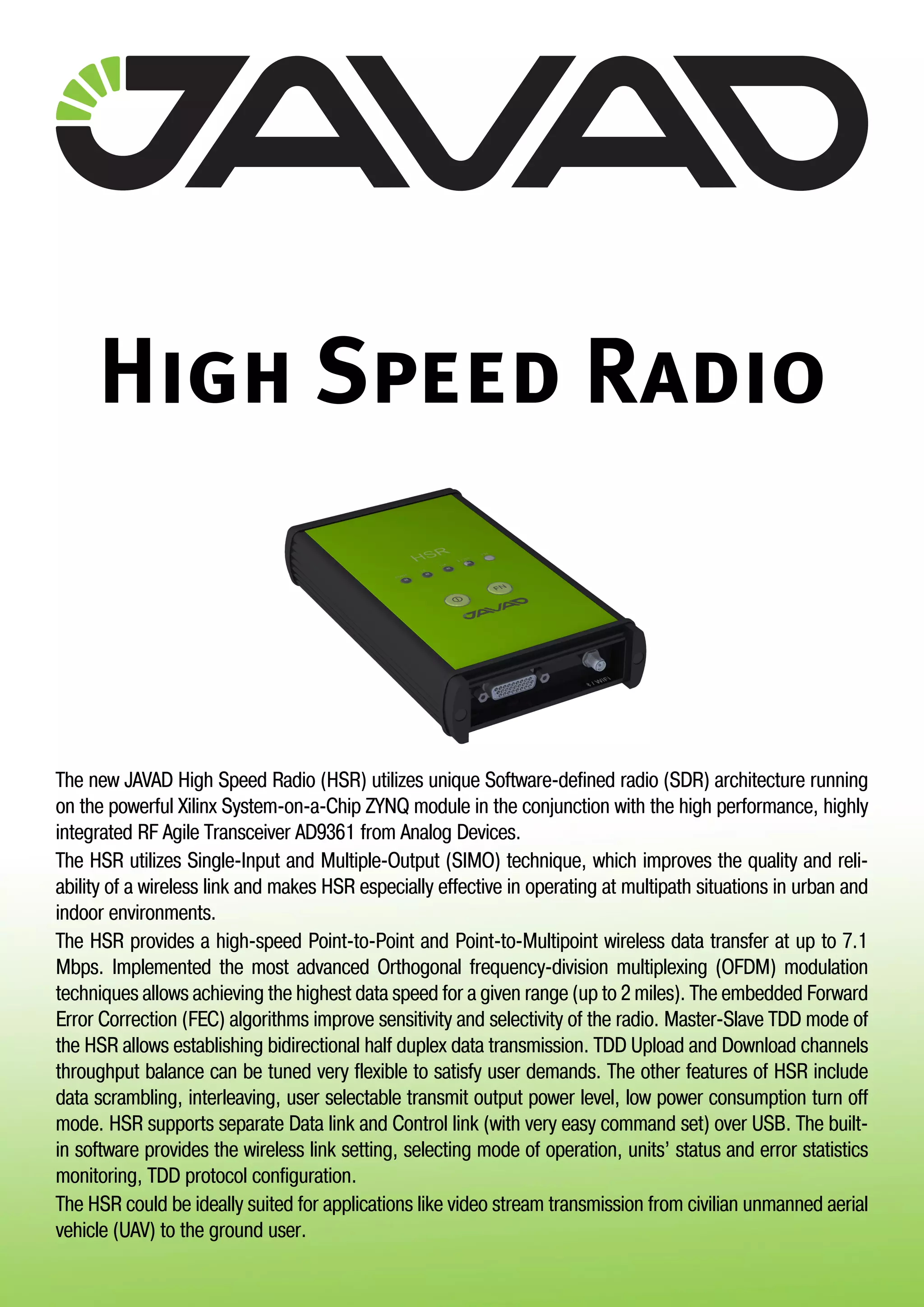
The JAVAD High Speed Radio (HSR) utilizes software-defined radio architecture and advanced modulation techniques to provide high-speed point-to-point and point-to-multipoint wireless data transfer of up to 7.1 Mbps over distances of up to 2 miles. It implements advanced OFDM and error correction to achieve high data rates and reliability. The HSR supports half-duplex TDD mode for bidirectional communication and includes features such as data scrambling and power control.
Transmission management in BSS is a feature used in managing the Base Station Subsystem transmission system functions such as supervision, alarms, statistics
and settings. The network element mainly responsible for transmission management in BSS is the Base Station Controller (BSC).
Transmission management functionalities make it possible for the operators to manage the transmission equipment remotely from the BSC or from Nokia
NetAct integrated network management system, which simplifies network maintenance and operation. Supervision functions help minimise the time spent in maintenance, and statistics collection helps the operators analyse and optimise
the use of their transmission equipment. Moreover, new software can be downloaded in a way that does not interfere with the traffic.
Hardware and software requirements BSS transmission network elements
BSS transmission management functionalities Transmission parameters Transmission alarms
Transmission measurements
2.Hardware and software requirements
There are no specific hardware or software requirements for the transmission management functionalities. However, the type of the BTS poses certain
limitations.
The BTS type specific functionalities are listed in the table below.
More details about the functionalities can be found in BSS transmission management functionalities .
Polling list sending with priority is a functionality used in positioning. To ensure accurate positioning calculations, the LMU unit must supply Radio Interface Timing System (RIT) information to the network faster than the normal Q1 polling is able to do. Faster LMU polling is achieved by defining a Q1 polling
priority for each Q1 device, with the LMU having the highest priority. For more information see Location Services .
3.BSS transmission network elements
The base Station Subsystem (BSS) consists of at least one Base Station Controller (BSC) and its Base Transceiver Stations (BTS). The Transcoder Submultiplexer
(TCSM) is also part of the BSS although it is actually located in the MSC site. The three basic configurations (topologies) for transmission between the BSC and
the BTSs are: point-to-point connection
multidrop chain multidrop loop
In point-to-point configuration each BTS is connected directly to the BSC. In the multidrop chain, BTSs form a chain and the first BTS in the network is connected directly to the BSC. In the loop connection, the BTSs form a loop where the first and the last BTS in the loop are connected directly to the BSC via a crossconnecting node. The topology used depends on a number of factors such as the distance between the BSC and the BTS, the number of transceivers (TRXs) used at a particular BTS site and the signalling channel rate between the BSC and the\ BTS. Usually the topology used is a mixture of the three basic topologies. Formore information on the topologies, refer to Nokia BSS Transmission\Configuration .
Flow Chart describes RET Alarms Troubleshooting in Huawei Node-B
* ALM-26751 RET Antenna Motor Fault
* ALM-26752 ALD Hardware Fault
* ALM-26754 RET Antenna Data Loss
* ALM-26753 RET Antenna Not Calibrated
* ALM-26541 ALD Maintenance Link Failure
* ALM-26530 RF Unit ALD Current Out of Range
* ALM-26531 RF Unit ALD Switch Configuration Mismatch
* ALM-26757 RET Antenna Running Data and Configuration Mismatch
Common core mechanics in Nokia UltraSite EDGE BTS Outdoor and Nokia UltraSite EDGE BTS Indoor
Common plug-in units
1940 x 770 x 750 mm (H x W x D)
Identical footprint to CityTalk BTS
Weight
Max weight (12 TRX) 340 kg
Heaviest single part 58 kg (core mechanics)
Heaviest plug-in unit 18 kg (RTC)
Acoustic noise (max): 68 dB(A)
Climatic conditions:
w/o heater -10°C ... +50°C
with optional heater -33°C ... +50°C
Ingress Protection Class: IP 55
Two level environmental protection:
BTS core and cabinet door provides EMC shielding
Outdoor kit provides additional weather proofing
Interventi, pareri, analisi e notizie della settimana 01 del 2015: jobs act, lavoro nella Pa, mondo impresa, economia, risorse umane, mercato del lavoro
Caribbean Racing Series, known as CRS, is an exclusive event
created with the mission to promote Motor Racing, providing a fair racing platform for all teams, regardless of size.
1. High Speed Radio
The new JAVAD High Speed Radio (HSR) utilizes unique Software-defined radio (SDR) architecture running
on the powerful Xilinx System-on-a-Chip ZYNQ module in the conjunction with the high performance, highly
integrated RF Agile Transceiver AD9361 from Analog Devices.
The HSR utilizes Single-Input and Multiple-Output (SIMO) technique, which improves the quality and reli-
ability of a wireless link and makes HSR especially effective in operating at multipath situations in urban and
indoor environments.
The HSR provides a high-speed Point-to-Point and Point-to-Multipoint wireless data transfer at up to 7.1
Mbps. Implemented the most advanced Orthogonal frequency-division multiplexing (OFDM) modulation
techniques allows achieving the highest data speed for a given range (up to 2 miles). The embedded Forward
Error Correction (FEC) algorithms improve sensitivity and selectivity of the radio. Master-Slave TDD mode of
the HSR allows establishing bidirectional half duplex data transmission. TDD Upload and Download channels
throughput balance can be tuned very flexible to satisfy user demands. The other features of HSR include
data scrambling, interleaving, user selectable transmit output power level, low power consumption turn off
mode. HSR supports separate Data link and Control link (with very easy command set) over USB. The built-
in software provides the wireless link setting, selecting mode of operation, units’ status and error statistics
monitoring, TDD protocol configuration.
The HSR could be ideally suited for applications like video stream transmission from civilian unmanned aerial
vehicle (UAV) to the ground user.
2. High Speed Radio
General High Speed Radio Specifications
•• Operating Center Frequency Range: 2.405 GHz - 2.495 GHz
•• Modulation Technique: OFDM QAM4
•• Media Access Control Protocols: Time Division Duplex (TDD)
•• Supported User Interfaces: Device Mode USB 2.0 HS
•• Supported Comms. Protocols: Transparent
•• Maximum Distance Range: 2 miles
•• Occupied Bandwidth: 10 MHz
•• Data Rate: 10MHz 256 subcarr
OFDM QAM4 Up to 7.1 Mbit/sec
•• System Gain (Antenna not incl.) 89dB
•• Communication Mode: TX, RX, TDD MASTER, TDD SLAVE
•• Carrier Power Stability: +1 dB / -2 dB
•• Receiver Sensitivity (BER 1x 10⁻⁴): -91 dBm
•• Receiver Dynamic Range: -91 to -30 dBm
SDR based OEM Radio Modem
•• Unlicensed operation mode
•• Data Speed over the air up to 7.1 Mbps
•• Programmable Output Power (0.0001 mW to 1 W)
•• Advanced Forward Error Correction (FEC)
•• SDR-Modem
•• Zero-IF Technologies
•• TX/RX/TDD Modes
•• Flexible TDD Timing Setup
•• Compact Design
•• Firmware can be upgraded for SIMO MRC
Power Specification
•• Input Voltage: +7V … +20V (3A max)
•• Power Consumption (average):
up to 17.5 W – transmit with 100% duty cycle (1 W TPO)
up to 7.5 W – receive mode
Communication Ports
•• Wi-Fi 2.4GHz and 5 GHz (IEEE 802.11 a, b, g, n, d, e, i)
•• Full-duplex 10BASE-T/100BASE-TX Ethernet port
•• Bluetooth 4.1 Compliance and CSA2 Support
•• Dual-Mode Bluetooth and Bluetooth LE
•• High Speed USB 2.0 configurable as Device port
•• MicroSD card slot (fully sealed)
•• Serial port configurable as RS232
Environmental
•• Enclosure aluminum extrusion, waterproof IP66
•• Humidity 100% condensing
•• Operation Temperature: -40o
C ... +60o
C
•• Storage Temperature: -400
C ... +80o
C
•• Weight 0.92 lbs (0.42 kg)
•• Dimensions 4.3 x 1.4 x 7.5 inches (109 x 35 x 188) mm with
connectors
External Connectors
•• MAIN, DIVERSITY, BLUETOOTH/Wi-Fi ANTENNA CONNECTOR
RP-SMA Female Bulkhead, RM, Crimp, RG-178 Linx Technologies,
Inc. p/n CONREVSMA014-R178 (23-500186-01)
•• SYSTEM CONNECTOR (J105) CONN,DSUB
HD,26P,FEM,RA,TH,P/MOUNT,IP67 CONEC p/n 15-002253
(285348)
Broadcasting
Radio Link
Long Range
Long Range
3. Communication and power port pinout
Pin # Signal name I/O Description
1 RTS_OUT O Request to Send (RS-232)
2 CTS_IN I Clear to Send (RS-232)
3 RESERVE - Do not connect
4 USB_DP I/O Data Positive line (USB)
5 USB_DM I/O Data Negative line (USB)
6 ELED O LED line (LAN)
7 ETD+ O Transmit Data positive line (LAN)
8 ERD+ I Receive Data positive line (LAN)
9 PWR_IN PWR +7.0 to +20 VDC Power Input
10 TXD_OUT O Transmit Data (RS-232)
11 RXD_IN I Receive Data (RS-232)
12 RESERVE - Do not connect
13 RESERVE - Do not connect
14 USB_VBUS PWR Power line (USB)
15 USB_ID I USB0 ID line
16 ETD- O Transmit Data negative line (LAN)
17 ERD- I Receive Data negative line (LAN)
18 PWR_IN PWR +7.0 to +20 VDC Power Input
19 GND PWR Power Ground
20 GND PWR Power Ground
21 GND PWR Power Ground
22 RESERVE - Do not connect
23 RESERVE - Do not connect
24 12VOUT PWR Load 0.3Amax
25 RESERVE - Do not connect
26 PWR_IN PWR +7.0 to +20 VDC Power Input
High Speed Radio
A1
A1
B1
B1
C2C2
C1
C1
97*
1.6+1
0.6 0.2
12.7*
12.7*
15*
1 2 3 4 5 6 7 8
A
B
C
D
E
F
G
TOP VIEW.
OUTSIDE ITEMS ARE SHOWN AS TRANSPARENT.
ITEM #12 NOT SHOWN
A
SECTION A1-A1
D
B
C
SECTION B1-B1
C2-C2
C1-C1
E
DETAIL B
SCALE 2.000
36 7 9
DETAIL C
SCALE 2.000
3 68 9
DETAIL D
SCALE 4.000
DETAIL E
SCALE 4.000
Drawing
item #
Part Number
Description Qty.
Tightening torque
Lbf*In
7 16-080037-01
Front Lid Self-Tapping Screw L=14mm 2 4.000 16
8 16-080038-01
Back Lid Self-Tapping Screw L=10mm 2 4.000 16
97*
108.6*
34.6*
1.7 0.253.2*
9 10 11 12 13 14 15 16
A
B
C
D
E
F
G
REVISIONS
ZONE REV DESCRIPTION DATE APPROVED
1
2
4
5
10
11
12
14
Drawing
item #
GNSS_PN Qty. DESCRIPTION MANUFACTURER / VENDOR M/F PART NUMBER Comment
1 02-660210-01 1 HSR Front Lid Assembly Javad EMS/JGNSS 02-660210-01 DSUB-26, SMA (BT / WiFi)
2 02-660220-01 1 HSR Back Lid Assembly Javad EMS/JGNSS 02-660220-01 2 x SMA (ANT, DIV); microSD
3 04-580301-01 4 Bopla Screw Cap Bopla 04-580301-01
is included into Kit ABD 1000; ABM 1000 AL; ABD
800; ABM 800 AL by Bopla
4 05-598902-01 1 HSR Power PCB Assembly JAVAD EMS/JGNSS 05-598902-01
5 10-580300-03 1 HSR Case 163.5 Javad GNSS 10-580300-03 Made from 10-580300-50
6 16-030017-01 4 FLAT TEFLON WASHER for M3 Seastrom 5612-31-20
7 16-080037-01 2 Front Lid Self-Tapping Screw L=14mm Bopla ---
is included into Kit ABM 1000 AL; ABM 800 AL by
Bopla
8 16-080038-01 2 Back Lid Self-Tapping Screw L=10mm Bopla --- is included into Kit ABD 1000; ABD 800 by Bopla
A1
A1
B1
B1
C2C2
C1
C1
180.4*
97*
188.4918*
1.6+1
0.6 0.2
12.7*
12.7*
15*
1 2 3 4 5 6 7 8
A
B
C
D
E
F
G
H
TOP VIEW.
OUTSIDE ITEMS ARE SHOWN AS TRANSPARENT.
ITEM #12 NOT SHOWN
Notes:
1. FOR COMPLETE PART DEFINITION SEE PRO/ENGINEER MODEL
01-660200-01_HS_RADIO_IN_CASE.ASM (OR 01-660200-01.STP)
2. * REFERENCES DIMENSION.
3. Approximated assembly weight is 0.399 kg.
A
SECTION A1-A1
D
B
C
SECTION B1-B1
C2-C2
C1-C1
E
DETAIL B
SCALE 2.000
36 7 9
DETAIL C
SCALE 2.000
3 68 9
DETAIL D
SCALE 4.000
DETAIL E
SCALE 4.000
item #
Description Qty.
Lbf*In
7 16-080037-01
Front Lid Self-Tapping Screw L=14mm 2 4.000 16
8 16-080038-01
Back Lid Self-Tapping Screw L=10mm 2 4.000 16
* All dimensions are in mm
4. Rev.1.0 September 14, 2016
Specifications are subject to change without notice
High Speed Radio
Diversity antenna RX only
FN button
On/Off button
Communication and power port
Bluetooth/WiFi antenna connector
MicroSD card door
LED indicators
Primary antenna TX/RX