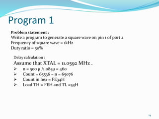
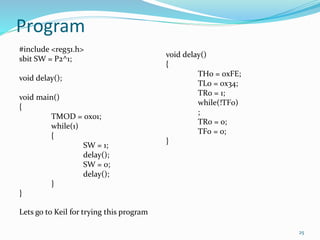
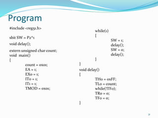
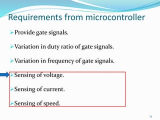
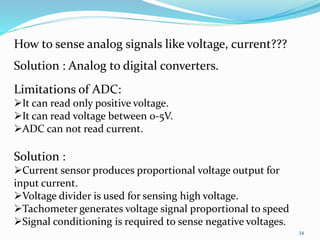
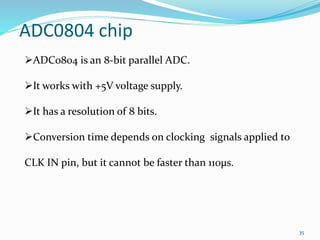
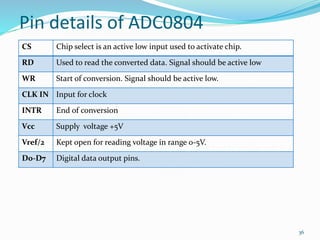
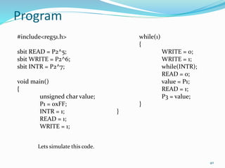
Jay Pandit 
12MT06PED016 
1
Contents 
 Keil 
 Proteus 
 Some basic techniques for C programming 
 Application 1 
 Application 2 
 Application 3 
2
3
How to start 1st Keil project.. 
Install keil software from the installation file. 
Start keil program from start menu or from desktop 
shortcut. 
4
Select New 
μvision Project 
5
Do not 
change the 
file type!!! 
6
Atmel 
7
AT89C51 
8
Create 
New File 
9
Save file 
as .c or 
.asm 
Right Click and select 
Add files to group 
Source 1 
10
Click Add 
11
12
Select Options for 
Target 
13
14
15 
Any one want to try this ?????
Before we start programming 
16 
Data Types in Embedded C 
Data Type Size in Bits Data range 
Unsigned char 8-bit 0 to 255 
(Signed) char 8-bit -128 to 127 
Unsigned int 16-bit 0 to 65535 
(Signed) int 16-bit -32768 to 32767 
sbit 1-bit SFR bit Addressable 
only 
Bit 1-bit RAM bit-addressable 
only 
sfr 8-bit RAM addresses
Before we start programming 
17 
Interrupt numbers in C 
Interrupt Name Number used by 8051 
External interrupt 0 INT0 0 
Timer interrupt 0 TF0 1 
External interrupt 1 INT1 2 
Timer interrupt 1 TF1 3 
Serial communication RI+TI 4
18 
For loop 
char i; 
for(i=0;i<10;i++) 
{ 
} 
Write your 
code here
19 
Infinite loop 
while(1) 
{ 
} 
Write your 
code here
Assembly instructions in C code 
20 
#pragma ASM 
Write your 
code here 
#pragma END ASM
21 
Functions 
int addition(int,int); 
void main() 
{ 
int i,j,k; 
i = 10; 
j = 10; 
k = addition(i,j); 
} 
int addition(int a, int b) 
{ 
int c 
c = a + b; 
return(c); 
}
Requirements from microcontroller 
Provide gate signals. 
What are your expectations 
from a microcontroller???? 
Variation in duty ratio of gate signals. 
Variation in frequency of gate signals. 
Sensing of voltage. 
Sensing of current. 
Sensing of speed. 
22
DC –DC Converter open loop 
 Gate signals are in the form of square wave 
 There may be change in duty ratio of gate 
signals. 
 There may be change in frequency of gate 
signals. 
23
Program 1 
24 
Problem statement : 
Write a program to generate a square wave on pin 1 of port 2 
Frequency of square wave = 1kHz 
Duty ratio = 50% 
Delay calculation : 
Assume that XTAL = 11.0592 MHz . 
 n = 500 μ /1.085μ = 460 
 Count = 65536 – n = 65076 
 Count in hex = FE34H 
 Load TH = FEH and TL =34H
Program 
25 
#include <reg51.h> 
sbit SW = P2^1; 
void delay(); 
void main() 
{ 
TMOD = 0x01; 
while(1) 
{ 
SW = 1; 
delay(); 
SW = 0; 
delay(); 
} 
} 
void delay() 
{ 
TH0 = 0xFE; 
TL0 = 0x34; 
TR0 = 1; 
while(!TF0) 
; 
TR0 = 0; 
TF0 = 0; 
} 
Lets go to Keil for trying this program
Program 2 
26 
Problem statement : 
Write a program to generate a square wave on pin 1 of port 2 
Frequency of square wave = 10kHz 
Duty ratio = variable. 
Time period of wave = 100 μsec 
We would be requiring two delays 
 One for on time. 
 Another for off time.
27 
Program 
#include <reg51.h> 
sbit SW P2^1 
void delay1(); 
void delay2(); 
extern char count; 
void main() 
{ 
count = 0; 
EA = 1; 
EX0 = 1; 
EX1 = 1; 
IT0 = 1; 
IT1 = 1; 
TMOD = 0x01; 
while(1) 
{ 
SW = 1; 
delay1(); 
SW = 0; 
delay2; 
} 
} 
void delay1() 
{ 
TH0 = 0xFF; 
TL0 = 210+count; 
TR0 = 1; 
while(!TF0) 
; 
TR0=0; 
TF0=0; 
}
28 
Program cont. 
void delay2() 
{ 
TH0 = 0xFF; 
TL0 = 210-count; 
TR0 = 1; 
while(!TF0) 
; 
TR0=0; 
TF0=0; 
} 
void external0() interrupt 0 
{ 
count++; 
} 
void external0() interrupt 1 
{ 
count--; 
} 
Lets try to simulate this program
Program 3 
29 
Problem statement : 
Write a program to generate a square wave on pin 1 of port 2 
Frequency of square wave = Variable. 
Duty ratio = 50%. 
Time period of wave = variable 
Hence, 
Count to be loaded in timer register = variable 
Requirements to be satisfied by the program 
User should be able to vary the frequency. 
Frequency raise and lower commands are given by user. 
There should be upper and lower limit on frequency.
30 
Solutions 
• Delay can be created using - Timers 
• User interface can be created by using - Interrupts 
How to satisfy these 
requirements using 
program???? 
• Limits can be put by using conditions like if-else
Program 
31 
#include <reg51.h> 
sbit SW = P2^1 
void delay(); 
extern unsigned char count; 
void main() 
{ 
count = 0x01; 
EA = 1; 
EX0 = 1; 
IT0 = 1; 
IT1 = 1; 
TMOD = 0x01; 
while(1) 
{ 
SW = 1; 
delay(); 
SW = 0; 
delay(); 
} 
} 
void delay() 
{ 
TH0 = 0xFF; 
TL0 = count; 
while(!TF0); 
TR0 = 0; 
TF0 = 0; 
}
32 
Program cont. 
void external0() interrupt 0 
{ 
if(count < 0xFA) 
count++; 
else 
count = 0xFA; 
} 
void external0() interrupt 1 
{ 
if(count > 0x01) 
count--; 
else 
count = 0x01; 
}
Requirements from microcontroller 
Provide gate signals. 
Variation in duty ratio of gate signals. 
Variation in frequency of gate signals. 
Sensing of voltage. 
Sensing of current. 
Sensing of speed. 
33
34 
How to sense analog signals like voltage, current??? 
Solution : Analog to digital converters. 
Limitations of ADC: 
It can read only positive voltage. 
It can read voltage between 0-5V. 
ADC can not read current. 
Solution : 
Current sensor produces proportional voltage output for 
input current. 
Voltage divider is used for sensing high voltage. 
Tachometer generates voltage signal proportional to speed 
Signal conditioning is required to sense negative voltages.
35 
ADC0804 chip 
ADC0804 is an 8-bit parallel ADC. 
It works with +5V voltage supply. 
It has a resolution of 8 bits. 
Conversion time depends on clocking signals applied to 
CLK IN pin, but it cannot be faster than 110μs.
36 
Pin details of ADC0804 
CS Chip select is an active low input used to activate chip. 
RD Used to read the converted data. Signal should be active low 
WR Start of conversion. Signal should be active low. 
CLK IN Input for clock 
INTR End of conversion 
Vcc Supply voltage +5V 
Vref/2 Kept open for reading voltage in range 0-5V. 
D0-D7 Digital data output pins.
37 
Relation of Vref/2 and Vin range 
Vref/2(V) Vin(V) Step size(mV) 
Not connected 0 to 5 19.53 
2.0 0 to 4 15.62 
1.5 0 to 3 11.71 
1.28 0 to 2.56 10 
Step size = Vin(max)/256
38 
How to calculate output 
Dout = Digital data output in decimal. 
Vin = analog input voltage. 
Dout = Vin/step size
39 
Program 4 
Problem statement: Using the ADC and current sensor 
read the value of current flowing in the branch of circuit, 
and display it on port3 
Solution: 
Current sensor ACS712ELCTR-20A-T is used. 
Current sensor can read current up to +/- 20A. 
Gain of current sensor (refer data sheet). 
ADC0804 is used. 
Internal clock is used.
40 
Program 
#include<reg51.h> 
sbit READ = P2^5; 
sbitWRITE = P2^6; 
sbit INTR = P2^7; 
void main() 
{ 
unsigned char value; 
P1 = 0xFF; 
INTR = 1; 
READ = 1; 
WRITE = 1; 
while(1) 
{ 
WRITE = 0; 
WRITE = 1; 
while(INTR); 
READ = 0; 
value = P1; 
READ = 1; 
P3 = value; 
} 
} 
Lets simulate this code.
Our achievements 
Provide gate signals. 
Variation in duty ratio of gate signals. 
Variation in frequency of gate signals. 
Sensing of voltage. 
Sensing of current. 
Sensing of speed. 
41
42

Jp

  • 1.
  • 2.
    Contents  Keil  Proteus  Some basic techniques for C programming  Application 1  Application 2  Application 3 2
  • 3.
  • 4.
    How to start1st Keil project.. Install keil software from the installation file. Start keil program from start menu or from desktop shortcut. 4
  • 5.
  • 6.
    Do not changethe file type!!! 6
  • 7.
  • 8.
  • 9.
  • 10.
    Save file as.c or .asm Right Click and select Add files to group Source 1 10
  • 11.
  • 12.
  • 13.
  • 14.
  • 15.
    15 Any onewant to try this ?????
  • 16.
    Before we startprogramming 16 Data Types in Embedded C Data Type Size in Bits Data range Unsigned char 8-bit 0 to 255 (Signed) char 8-bit -128 to 127 Unsigned int 16-bit 0 to 65535 (Signed) int 16-bit -32768 to 32767 sbit 1-bit SFR bit Addressable only Bit 1-bit RAM bit-addressable only sfr 8-bit RAM addresses
  • 17.
    Before we startprogramming 17 Interrupt numbers in C Interrupt Name Number used by 8051 External interrupt 0 INT0 0 Timer interrupt 0 TF0 1 External interrupt 1 INT1 2 Timer interrupt 1 TF1 3 Serial communication RI+TI 4
  • 18.
    18 For loop char i; for(i=0;i<10;i++) { } Write your code here
  • 19.
    19 Infinite loop while(1) { } Write your code here
  • 20.
    Assembly instructions inC code 20 #pragma ASM Write your code here #pragma END ASM
  • 21.
    21 Functions intaddition(int,int); void main() { int i,j,k; i = 10; j = 10; k = addition(i,j); } int addition(int a, int b) { int c c = a + b; return(c); }
  • 22.
    Requirements from microcontroller Provide gate signals. What are your expectations from a microcontroller???? Variation in duty ratio of gate signals. Variation in frequency of gate signals. Sensing of voltage. Sensing of current. Sensing of speed. 22
  • 23.
    DC –DC Converteropen loop  Gate signals are in the form of square wave  There may be change in duty ratio of gate signals.  There may be change in frequency of gate signals. 23
  • 24.
    Program 1 24 Problem statement : Write a program to generate a square wave on pin 1 of port 2 Frequency of square wave = 1kHz Duty ratio = 50% Delay calculation : Assume that XTAL = 11.0592 MHz .  n = 500 μ /1.085μ = 460  Count = 65536 – n = 65076  Count in hex = FE34H  Load TH = FEH and TL =34H
  • 25.
    Program 25 #include<reg51.h> sbit SW = P2^1; void delay(); void main() { TMOD = 0x01; while(1) { SW = 1; delay(); SW = 0; delay(); } } void delay() { TH0 = 0xFE; TL0 = 0x34; TR0 = 1; while(!TF0) ; TR0 = 0; TF0 = 0; } Lets go to Keil for trying this program
  • 26.
    Program 2 26 Problem statement : Write a program to generate a square wave on pin 1 of port 2 Frequency of square wave = 10kHz Duty ratio = variable. Time period of wave = 100 μsec We would be requiring two delays  One for on time.  Another for off time.
  • 27.
    27 Program #include<reg51.h> sbit SW P2^1 void delay1(); void delay2(); extern char count; void main() { count = 0; EA = 1; EX0 = 1; EX1 = 1; IT0 = 1; IT1 = 1; TMOD = 0x01; while(1) { SW = 1; delay1(); SW = 0; delay2; } } void delay1() { TH0 = 0xFF; TL0 = 210+count; TR0 = 1; while(!TF0) ; TR0=0; TF0=0; }
  • 28.
    28 Program cont. void delay2() { TH0 = 0xFF; TL0 = 210-count; TR0 = 1; while(!TF0) ; TR0=0; TF0=0; } void external0() interrupt 0 { count++; } void external0() interrupt 1 { count--; } Lets try to simulate this program
  • 29.
    Program 3 29 Problem statement : Write a program to generate a square wave on pin 1 of port 2 Frequency of square wave = Variable. Duty ratio = 50%. Time period of wave = variable Hence, Count to be loaded in timer register = variable Requirements to be satisfied by the program User should be able to vary the frequency. Frequency raise and lower commands are given by user. There should be upper and lower limit on frequency.
  • 30.
    30 Solutions •Delay can be created using - Timers • User interface can be created by using - Interrupts How to satisfy these requirements using program???? • Limits can be put by using conditions like if-else
  • 31.
    Program 31 #include<reg51.h> sbit SW = P2^1 void delay(); extern unsigned char count; void main() { count = 0x01; EA = 1; EX0 = 1; IT0 = 1; IT1 = 1; TMOD = 0x01; while(1) { SW = 1; delay(); SW = 0; delay(); } } void delay() { TH0 = 0xFF; TL0 = count; while(!TF0); TR0 = 0; TF0 = 0; }
  • 32.
    32 Program cont. void external0() interrupt 0 { if(count < 0xFA) count++; else count = 0xFA; } void external0() interrupt 1 { if(count > 0x01) count--; else count = 0x01; }
  • 33.
    Requirements from microcontroller Provide gate signals. Variation in duty ratio of gate signals. Variation in frequency of gate signals. Sensing of voltage. Sensing of current. Sensing of speed. 33
  • 34.
    34 How tosense analog signals like voltage, current??? Solution : Analog to digital converters. Limitations of ADC: It can read only positive voltage. It can read voltage between 0-5V. ADC can not read current. Solution : Current sensor produces proportional voltage output for input current. Voltage divider is used for sensing high voltage. Tachometer generates voltage signal proportional to speed Signal conditioning is required to sense negative voltages.
  • 35.
    35 ADC0804 chip ADC0804 is an 8-bit parallel ADC. It works with +5V voltage supply. It has a resolution of 8 bits. Conversion time depends on clocking signals applied to CLK IN pin, but it cannot be faster than 110μs.
  • 36.
    36 Pin detailsof ADC0804 CS Chip select is an active low input used to activate chip. RD Used to read the converted data. Signal should be active low WR Start of conversion. Signal should be active low. CLK IN Input for clock INTR End of conversion Vcc Supply voltage +5V Vref/2 Kept open for reading voltage in range 0-5V. D0-D7 Digital data output pins.
  • 37.
    37 Relation ofVref/2 and Vin range Vref/2(V) Vin(V) Step size(mV) Not connected 0 to 5 19.53 2.0 0 to 4 15.62 1.5 0 to 3 11.71 1.28 0 to 2.56 10 Step size = Vin(max)/256
  • 38.
    38 How tocalculate output Dout = Digital data output in decimal. Vin = analog input voltage. Dout = Vin/step size
  • 39.
    39 Program 4 Problem statement: Using the ADC and current sensor read the value of current flowing in the branch of circuit, and display it on port3 Solution: Current sensor ACS712ELCTR-20A-T is used. Current sensor can read current up to +/- 20A. Gain of current sensor (refer data sheet). ADC0804 is used. Internal clock is used.
  • 40.
    40 Program #include<reg51.h> sbit READ = P2^5; sbitWRITE = P2^6; sbit INTR = P2^7; void main() { unsigned char value; P1 = 0xFF; INTR = 1; READ = 1; WRITE = 1; while(1) { WRITE = 0; WRITE = 1; while(INTR); READ = 0; value = P1; READ = 1; P3 = value; } } Lets simulate this code.
  • 41.
    Our achievements Providegate signals. Variation in duty ratio of gate signals. Variation in frequency of gate signals. Sensing of voltage. Sensing of current. Sensing of speed. 41
  • 42.