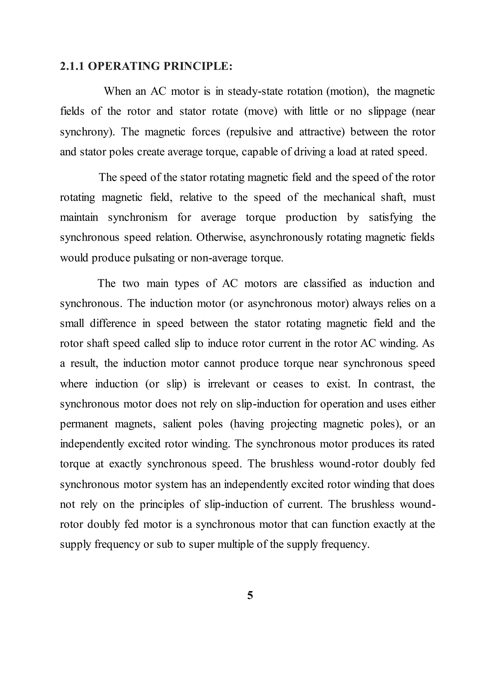
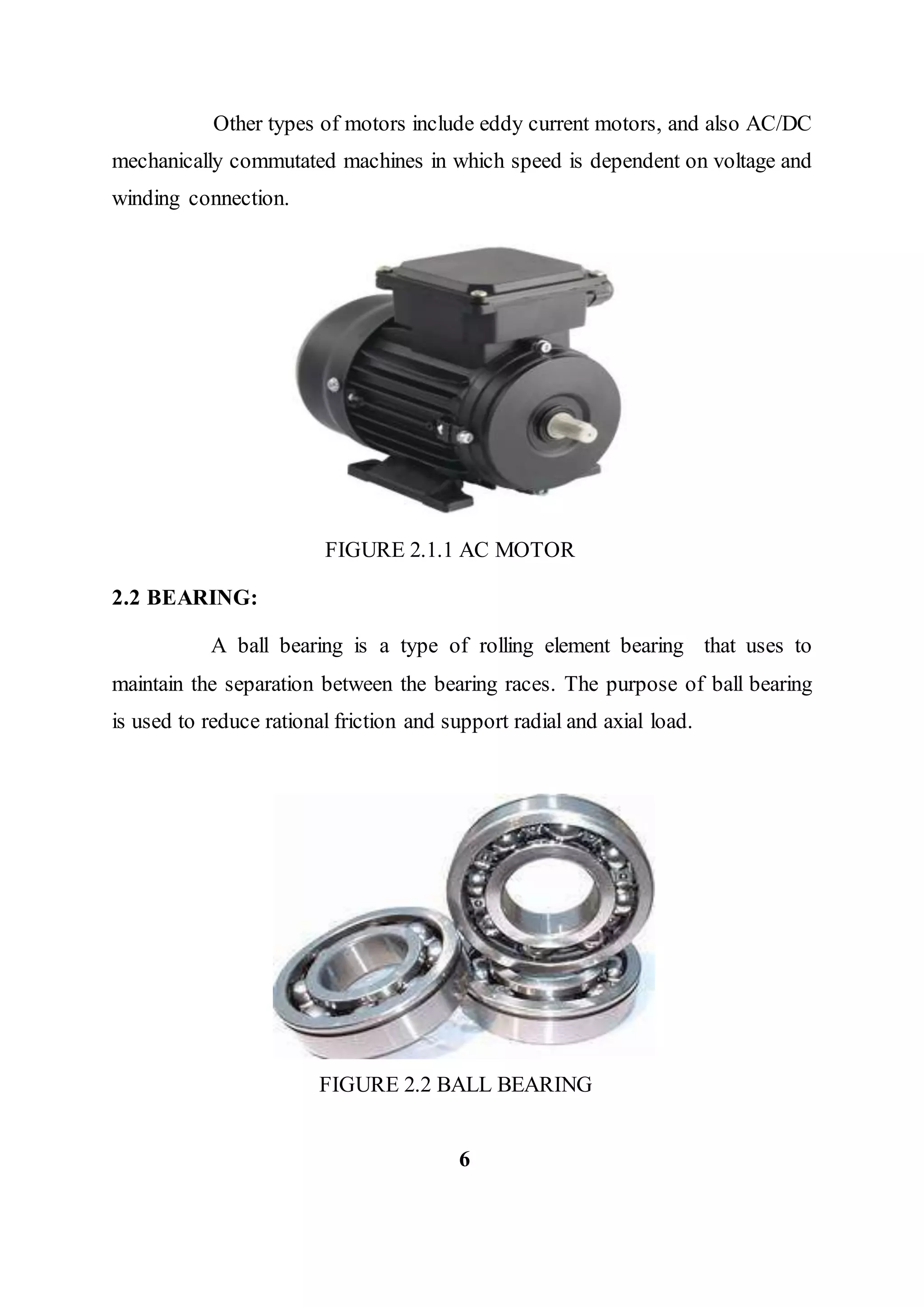
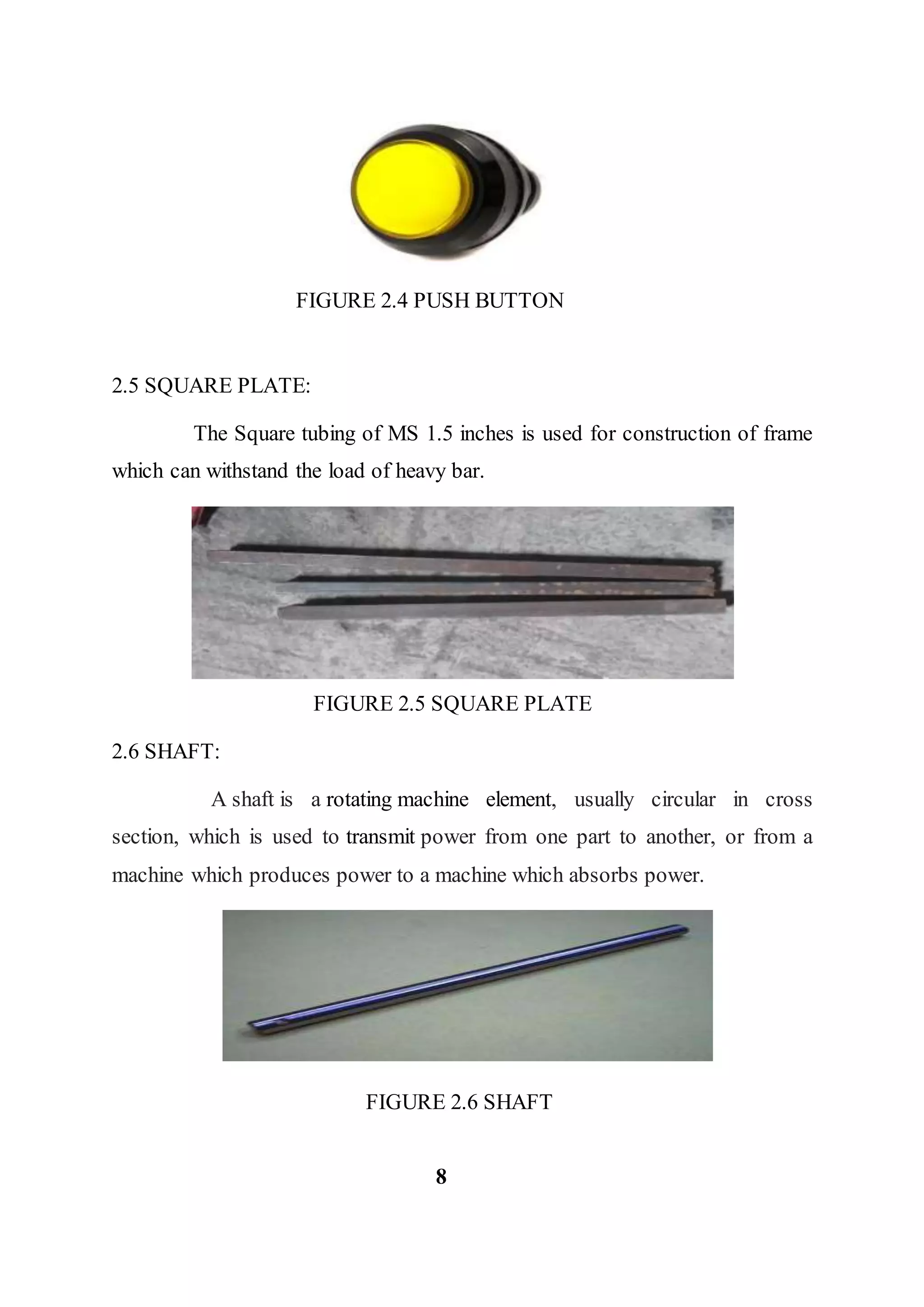
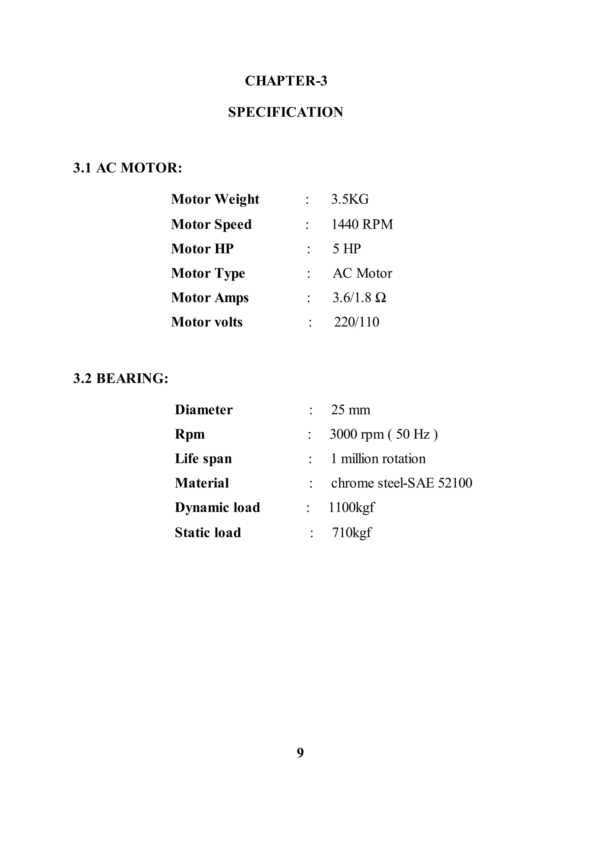
DESIGN AND FABRICATION OF AUTOMATIC FEEDING
MECHANISM FOR POWER HACKSAW MACHINE
A MINI PROJECT REPORT
Submitted by
ARAVINTH CHANDRA KUMAR R 310815114010
AROCKIA ALEX FRANKIN X 310815114012
ASHWIN RAJU R 310815114019
GOPINATH S 310815114042
In partial fulfillment for the award of the degree
Of
BACHELOR OF ENGINEERING
In
MECHANICAL ENGINEERING
JEPPIAAR ENGINEERING COLLEGE
CHENNAI -119
ANNA UNIVERSITY: CHENNAI –25
APRIL – 2018
ANNA UNIVERSITY: CHENNAI-600025
JEPPIAAR ENGINEERING COLLEGE
DEPARTMENT OF MECHANICAL ENGINEERING
Jeppiaar Nagar, Rajiv Gandhi Salai, Chennai –119
BONAFIDE CERTIFICATE
Certified that this project report “DESIGN AND FABRICATION OF AUTOMATIC
FEEDING MECHANISM FOR POWER HACKSAW MACHINE” is the bonafide
work of “ARAVINTH CHANDRA KUMAR R (310815114010), AROCKIA ALEX
FRANKIN X (310815114012), ASHWIN RAJU R (310815114019), GOPINATH S
(310815114042)” who carried out the project under my supervision. Submitted for the
examination held on __________
SIGNATURE SIGNATURE
Dr. V. Natarajan., M.E., Ph.D., Mr.K.JAGATHEESHAN, M.E.,(Ph.D).,
HEAD OF THE DEPARTMENT SUPERVISOR
PROFESSOR ASSISTENT PROFESSOR
Dept. of Mechanical Engineering, Dept. of Mechanical Engineering,
Jeppiaar Engineering College, Jeppiaar Engineering College,
Chennai-600119. Chennai-600119.
INTERNAL EXAMINER EXTERNAL EXAMINER
ACKNOWLEDGEMENT
We would like to take this opportunity to express our heartest gratitude to the
following people for their invaluable help rendered durng our project period at
JEPPIAAR ENGINEERING COLLEGE.
We express our sincere thanks to our Hon’ble ColonelDr.JEPPIAAR,M.A.,
B.L, Ph.D., (Late), our Chairman and Managing Director Dr. M. REGEENA
JEPPIAAR, B. Tech., M.B.A., Ph.D., for their constant supportand
encouragement in studies.
We express our gratitude to our Principal Dr. J.VENUGOPALAKRISHNAN,
M.Tech., F.I.E., Ph.D., forhis indispensable help,amenities provided to carry
out our project work.
We would like to express our heartful thanks to Prof. Dr. V. Natarajan., M.E.,
Ph.D., Head of the Department of Mechanical Engineering for his support and
encouragement towards the project work.
We would like to express our best and sincere thanks to our project guide
Mr.K.JAGATHEESHAN, M.E.,(Ph.D)., for giving valuable suggestions for
making this project a grand success.
We also thank the teaching and non teaching staff members of the department
of MECHANICAL ENGINEERING for their constant support.
i
ABSTRACT
Nowadays, automation in the industries plays an important role.
Almost all the machines are atomized. The electronic switches and AC motors
are used for doing this automation process. This is one of the automation
processes by using the torque motor. The “AUTOMATIC FEEDING
MECHANISM FOR POWER HACKSAW MACHINE” is our project,
which is fixed with the motor and with the electronic automations.The motor
controls the bar in the mechanism automatically by using the electronic
automations. The bar can be moved in the mechanism with the regular time
interval. This results ease in the process of feeding the workpiece in power
hacksaw .
ii
TABLE OF CONTENTS
CHAPTER TITLE PAGE
NO. NO.
ABSTRACT ii
LIST OF FIGURES vi
LIST OF TABLES vii
1 INTRODUCTION 1
1.1 GENERAL 1
1.2 NEED FOR AUTOMATION 1
1.3 DEVELOPMENT OF AUTOMATION 2
1.4 PROBLEM DEFINITON FOR 2
MANUAL FEEDING
2 COMPONENTS USED 4
2.1 AC MOTOR 4
2.2 BEARING 6
2.3 PULLEY AND ROPE 7
2.4 PUSH BUTTON 7
2.5 SQUARE PLATE 8
2.6 SHAFT 9
iii
CHAPTER TITLE PAGE
NO. NO.
3 SPECIFICATION 9
3.1 AC MOTOR 9
3.2 BEARING 9
4 AUTOMATIC BAR FEEDING 10
MECHANISM
4.1 WORKING 10
4.2 CONTROLOF MOTOR SPEED 11
4.3 CONTROLOF PUSH BUTTON 12
5 CATIA V5 3D MODELING 12
5.1 ISOMETERIC VIEW 12
5.2 FRONT VIEW 12
5.3 TOP VIEW 13
5.4 RIGHT SIDE VIEW 13
6 MATERIALS USED 14
7 FABRICATION PROCESS 15
7.1 TURNING 15
7.2 FACING 16
7.3 DRILLING 16
7.4 ARC WELDING 17
iv
CHAPTER TITLE PAGE
NO. NO.
8 WORKING 18
8.1 BLOCK DIAGRAM 18
9 DESIGN CALCULATION 19
10 BENEFITS 20
10.1 ADVANTAGES 20
10.2 LIMITATION 20
10.3 APPLICATION 21
11 COST ESTIMATION 22
12 CONCLUSION 23
13 PHOTOGRAPHY 24
14 FUTURE IMPROVEMENTSAND 26
INNOVATION
15 REFERENCE 27
v
LIST OF FIGURES
FIGURE TITLE PAGE
NO NO
1.4 MANUAL FEEDING 2
2.1.1 AC MOTOR 4
2.2 BEARING 6
2.3 PULLEY 7
2.4 PUSH BUTTON 7
2.5 SQUARE PLATE 8
2.6 SHAFT 8
7.1 TURNING 15
7.2 FACING 16
7.3 DRILLING 16
7.4 ARC WELDING 17
vi
LIST OF TABLES
TABLE TITLE PAGE
NO NO.
6.1 MATERIALS USED 14
11.1 COST ESTIMATION 22
vii
CHAPTER-1
INTRODUCTION
Automation or automatic control, is the use of various control
systems for operating equipment such as machinery, processes in factories,
boilers and heat treating ovens, switching on telephone networks, steering and
stabilization of ships, aircraft and other applications and vehicles with minimal
or reduced human intervention. Some processes have been completely
automated.The biggest benefit of automation is that it saves labor; however, it is
also used to save energy and materials and to improve quality, accuracy and
precision.
1.1 GENERAL:
The term automation, inspired by the earlier word automatic (coming
from automaton), was not widely used before 1947, when Ford established an
automation department. It was during this time that industry was rapidly
adopting feedback controllers, which were introduced in the 1930s.
1.2 NEED FOR AUTOMATION:
During observation it was found that the bar which is to be cut was
feeded by using manual.There are no proper equipments to fed the bar in the
machine , the bar is rest on the hand which we can see in the picture due to
which sometimes the bar is being cut in wrong dimensions
To overcome this problems automation was needed for cutting the
bar in accuracy as well to reduce human efforts and to reduce wastage of raw
material.Therefore by using stands and mechanized motion the problem is
solved .
1
1.3 DEVELOPMENT OF AUTOMATION:
Automation has been achieved by various means including
mechanical, hydraulic, pneumatic, electrical, electronic devices and computers,
usually in combination. Complicated systems, such as modern factories,
airplanes and ships typically use all these combined technique. Nowadays
almost all the manufacturing process is being atomized in order to deliver the
products at a faster rate.
1.4 PROBLEMS DEFINITION FOR MANUAL FEEDING:
 Length or size variations.
 Improper cutting.
 Wastage of raw materials.
 More time required to adjust required length.
2
FIGURE 1.4 MANUAL FEEDING
1.5 ADVANTAGAES FOR AUTOMATIC FEEDING MECHANISM:
 Reducing man power
 Simple in construction.
 It can used for solid as well as hollow materials.
 Accuracy and precision.
 More productivity.
3
CHAPTER-2
COMPONENTS USED
The prototype was created using following parts:
AC MOTOR : used to drive entire shaft setup
BEARING : used to rotated the driving shaft
PULLEY AND ROPE : used to transmitted the power
PUSH BUTTON : used to cut off/on the power
SQUARE PLATE : used to constructing the frame
SHAFT : used to transmit the power
2.1 AC MOTOR:
An AC motor is an electric motor driven by an alternating current (AC).
The AC motor commonly consists of two basic parts, an outside
stationary stator having coils supplied with alternating current to produce a
rotating magnetic field, and an inside rotor attached to the output shaft
producing a second rotating magnetic field. The rotor magnetic field may be
produced by permanent magnets, reluctance saliency, or DC or AC electrical
windings.
Less commonly, linear AC motors operate on similar principles as
rotating motors but have their stationary and moving parts arranged in a straight
line configuration, producing linear motion instead of rotation.
4
2.1.1 OPERATING PRINCIPLE:
When an AC motor is in steady-state rotation (motion), the magnetic
fields of the rotor and stator rotate (move) with little or no slippage (near
synchrony). The magnetic forces (repulsive and attractive) between the rotor
and stator poles create average torque, capable of driving a load at rated speed.
The speed of the stator rotating magnetic field and the speed of the rotor
rotating magnetic field, relative to the speed of the mechanical shaft, must
maintain synchronism for average torque production by satisfying the
synchronous speed relation. Otherwise, asynchronously rotating magnetic fields
would produce pulsating or non-average torque.
The two main types of AC motors are classified as induction and
synchronous. The induction motor (or asynchronous motor) always relies on a
small difference in speed between the stator rotating magnetic field and the
rotor shaft speed called slip to induce rotor current in the rotor AC winding. As
a result, the induction motor cannot produce torque near synchronous speed
where induction (or slip) is irrelevant or ceases to exist. In contrast, the
synchronous motor does not rely on slip-induction for operation and uses either
permanent magnets, salient poles (having projecting magnetic poles), or an
independently excited rotor winding. The synchronous motor produces its rated
torque at exactly synchronous speed. The brushless wound-rotor doubly fed
synchronous motor system has an independently excited rotor winding that does
not rely on the principles of slip-induction of current. The brushless wound-
rotor doubly fed motor is a synchronous motor that can function exactly at the
supply frequency or sub to super multiple of the supply frequency.
5
Other types of motors include eddy current motors, and also AC/DC
mechanically commutated machines in which speed is dependent on voltage and
winding connection.
FIGURE 2.1.1 AC MOTOR
2.2 BEARING:
A ball bearing is a type of rolling element bearing that uses to
maintain the separation between the bearing races. The purpose of ball bearing
is used to reduce rational friction and support radial and axial load.
FIGURE 2.2 BALL BEARING
6
2.3 PULLEY AND ROPE:
V-belt Pulley image V-belt pulleys (also called v belt sheaves) are
devices which transmit power between axles by the use of a v-belt, a
mechanical linkage with a trapezoidal cross-section. Together these devices
offer a high-speed power transmission solution that is resistant to slipping and
misalignment.
Typically, v-belt drives operate between 1,500 to 6,000 ft/min, with
4,500 ft/min the ideal capacity for standard belts. Some narrow v-belts can
operate at speeds of up to 10,000 ft./min, but these pulleys must be dynamically
stabilized.
FIGURE 2.3 PULLEY
2.4 PUSH BUTTON:
The main function of the push button in our project is to cut off the
power to the motor as soon as the bar touches the button to avoid over feeding
of bar and to get the exact dimensions of bar . This push button is located on the
end side of the machine.
7
FIGURE 2.4 PUSH BUTTON
2.5 SQUARE PLATE:
The Square tubing of MS 1.5 inches is used for construction of frame
which can withstand the load of heavy bar.
FIGURE 2.5 SQUARE PLATE
2.6 SHAFT:
A shaft is a rotating machine element, usually circular in cross
section, which is used to transmit power from one part to another, or from a
machine which produces power to a machine which absorbs power.
FIGURE 2.6 SHAFT
8
CHAPTER-3
SPECIFICATION
3.1 AC MOTOR:
Motor Weight : 3.5KG
Motor Speed : 1440 RPM
Motor HP : 5 HP
Motor Type : AC Motor
Motor Amps : 3.6/1.8 Ω
Motor volts : 220/110
3.2 BEARING:
Diameter : 25 mm
Rpm : 3000 rpm ( 50 Hz )
Life span : 1 million rotation
Material : chrome steel-SAE 52100
Dynamic load : 1100kgf
Static load : 710kgf
9
CHAPTER- 4
AUTOMATIC FEEDING MECHANISM
4.1 WORKING:
The work piece which is to be machined is placed in the rotary bar.
When the motor is switched ON motor will be rotated, the pulley will rotate due
to the friction due to the rope placed between the motor and pulley so that the
bar is moving from initial position to the determined position.Length adjusting
unit with push button is used to determine the bar dimension to be cut.When rod
reaches and touches the push button electric supply stops and motor stops
rotating.Hence the rod stops moving. And further clamping the vice,the rod
cutting process will starts.
What is Feed Mechanism?
The Feeding mechanism is a metal cutting machine tool
designed to feed the metal. The machine is exclusively intended for mass
production and they represent fasten and more efficient way to feed a metal.
How Feed Mechanism works?
In feed mechanisms which have been proposed and used
include shaft feeding the bar through the machine by rotation of the shaft. It is
the objective of this invention to provide a feed mechanism for a power
hacksaw in a form which minimizes damage both to the bar stock and to the bar
contacting shaft surfaces.
10
4.2 CONTROL OF MOTOR SPEED :
This push-button operated AC motor speed controller uses
Phase Angle Regulation (PAR) and a triac output and allows you to adjust the
speed of 230Vac 50Hz single-phase "universal" motors as used in power drills,
vacuum cleaners, etc and an operating load of up to 750 Watts.
4.3 CONTROL OF PUSH BUTTON:
A push-button (also spelled pushbutton) or simply button is a
simple switch mechanism for controlling some aspect of a machine or a process.
Buttons are typically made out of hard material, usually plastic or metal. The
surface is usually flat or shaped to accommodate the human finger or hand, so
as to be easily depressed or pushed. Buttons are most often biased switches,
although many un-biased buttons (due to their physical nature) still require a
spring to return to their un-pushed state. Terms for the "pushing" of a button
include pressing, depressing, mashing, hitting, and punching.
11
CHAPTER-5
CATIAV5 3D MODELING
5.1 ISOMETERIC VIEW:
5.2 FRONT VIEW:
12
5.3 TOP VIEW:
5.4 RIGHT SIDE VIEW:
13
CHAPTER-6
MATERIALS
COMPONENTS MATERIALS DIMENSIONS
BEARING Low carbon alloy
Inner Diameter : 25mm
Outer Diameter: 31mm
SHAFT Mild steel
Diameter : 25mm
Length : 110cm
FRAME Mild steel (110x45) Rectangular
Frame
AC MOTOR Speed : 1440rpm
ADJUSTING
STOPPER
Aluminium steel
Length : 35cm
Breath : 15cm
Hole : 10mm
ROLLER DRIVE Rubber Material Diameter : 25mm
PULLEY AND ROPE Mild steel & Rubber
material
Diameter : 25mm
Height : 95mm
Thickness : 1.5mm
TABLE 6.1 : MATERIALS USED
14
CHAPTER-7
FABRICATION PROCESSES
7.1 TURNING:
This operation is one of the most basic machining processes. That is,
the part is rotated while a single point cutting tool is moved parallel to the axis
of rotation. Turning can be done on the external surface of the part as well as
internally (boring). The starting material is generally a work piece generated by
other processes such as casting, forging, extrusion, or drawing.
FIGURE 7.1: TURNING
15
Fabrication
process
Frame
Welding
Drilling
Shaft
Turning
facing
7.2 FACING:
Facing in the context of turning work involves moving the cutting tool
at right angles to the axis of rotation of the rotating work piece. This can be
performed by the operation of the cross-slide, if one is fitted, as distinct from
the longitudinal feed (turning). It is frequently the first operation performed in
the production of the work piece, and often the last—hence the phrase "ending
up".
FIGURE 7.2: FACING
7.3 DRILLING:
Drilling is a cutting process that uses a drill bit to cut a hole of
circular cross-section in solid materials. The drill bit is usually a rotary cutting
tool, often multipoint. The bit is pressed against the work piece and rotated at
rates from hundreds to thousands of revolutions per minute. This forces the
cutting edge against the work piece, cutting off chips (swarf) from the hole as it
is drilled. In rock drilling, the hole is usually not made through a circular cutting
motion, though the bit is usually rotated. Instead, the hole is usually made by
hammering a drill bit into the hole with quickly repeated short movements. The
hammering action can be performed from outside of the hole (top-hammer drill)
or within the hole (down-the-hole drill, DTH). Drills used for horizontal drilling
are called drifter drills.
16
In rare cases, specially-shaped bits are used to cut holes of non-circular
cross-section; a square cross-section is possible.
FIGURE 7.3: DRILLING
7.4 ARC WELDING:
Arc welding is a process that is used to join metal to metal by using
electricity to create enough heat to melt metal, and the melted metals when cool
result in a binding of the metals. It is a type of welding that uses a welding
power supply to create an electric arc between an electrode and the base
material to melt the metals at the welding point.
FIGURE 7.4: ARC WELDING
17
CHAPTER-8
WORKING
The work piece which is to be machined is placed in the rotary bar. When
the motor is switched ON motor will be rotated, the pulley will rotate due to the
friction due to the rope placed between the motor and pulley so that the bar is
moving from initial position to the determined position.
Length adjusting unit with push button is used to determine the bar
dimension to be cut. When rod reaches and touches the push button electric
supply stops and motor stops rotating.
Hence the rod stops moving and further clamping the vice,the rod cutting
process will starts.
8.1 BLOCK DIAGRAM:
18
MOTOR PULLEY BEARING
FEEDING
WORKPECE
CHAPTER-9
DESIGN CALCULATION
MOTOR INTIAL SPEED WITHOUT LOAD : 1500rpm
MOTOR INTIAL SPEED WITH LOAD : 1480rpm
TRIALS : Dimension ɸ25x100mm
MANUAL AUTO
1hr = 15 rod 1hr = 18 rod
8hrs = 120 rods 8hrs = 144 rods
By using “AUTOMATIC FEEDING MECHANISM FOR POWER
HACKSAW MACHINE” we can save 2 hrs/day, 24 pieces increases per
shift.
19
CHAPTER-10
BENEFITS.
10.1 ADVANTAGES:
 Reducing man power
 Simple in construction.
 It can used for solid as well as hollow materials.
 Accuracy and precision.
 More productivity.
10.2 LIMITATIONS:
 Limited weight material only used
 Inital amount is high.
20
10.3 APPLICATION:
 Small and Medium scale industries Application
 Metal Cutting Industries and Work Shops
 Pipe cutting
 Splendor rod cutting
 Round, Square, Oval, Hexagonal, etc shape materials can also feed by
using this mechanism.
21
CHAPTER-11
COST ESTIMATION
TOTAL 3670
TABLE 11.1 COST ESTIMATION
22
COMPONENTS NO’S COST
MOTOR 1 1500
WELDING & DRILLING 700
SQUARE PLATE 12KG 500
STEEL PLATE 2 300
BALL BEARING 2 240
PULLEY 2 200
CUTTING TOOL 1 140
NUTS AND BOLTS 10 50
ROPE 1 40
CHAPTER-12
CONCLUSION
The “AUTOMATIC FEEDING MECHANISM FOR POWER
HACKSAW MACHINE” is working with satisfactory conditions.
While concluding this report, we feel quite fulfill in having
completed the project assignment well on time, we had enormous practical
experience on fulfillment of the manufacturing schedules of the working project
model. We are therefore, happy to state that the in calculation of mechanical
aptitude proved to be a very useful purpose.
23
CHAPTER-13
PHOTOGRAPHY
FRONT VIEW:
24
TOP VIEW:
25
CHAPTER-14
FUTURE IMPROVEMENTS AND INNOVATIONS
The paper included very simple type of Machine parts requiring
very less component than conventional machinery. As work was successful
studying & completing the results of this automatic feeding mechanism for
hacksaw with solving other types of conventional feeding problems associated
with machine that can be implemented from higher to lower units cost. Its lower
most requirement of maintenance can again be beneficial for keeping cost
down. This automation can surely reduce the loss thereby increasing the
productivity by investing small capital less equipments. As per Indian content is
concern this machine can be very beneficial for virtually all type of power
hacksaw machines as it has very low capital investment. This machine may
form a simple solution for feeding of bar in the future. This automation also can
be controlled by computer programs.
26
CHAPTER-15
REFERENCES
1. Khurmi and Gupta “Theory of Machine” Edition Reprint 2007.
2. Khurmi and Gupta “Machine Design” Edition 2005.
3. Workshop Technology, Hajara Chaudhari.
4. Production Technology, R.K. Jain.
5. PSG Design Data Book.
27

Mini project

  • 1.
    DESIGN AND FABRICATIONOF AUTOMATIC FEEDING MECHANISM FOR POWER HACKSAW MACHINE A MINI PROJECT REPORT Submitted by ARAVINTH CHANDRA KUMAR R 310815114010 AROCKIA ALEX FRANKIN X 310815114012 ASHWIN RAJU R 310815114019 GOPINATH S 310815114042 In partial fulfillment for the award of the degree Of BACHELOR OF ENGINEERING In MECHANICAL ENGINEERING JEPPIAAR ENGINEERING COLLEGE CHENNAI -119 ANNA UNIVERSITY: CHENNAI –25 APRIL – 2018
  • 2.
    ANNA UNIVERSITY: CHENNAI-600025 JEPPIAARENGINEERING COLLEGE DEPARTMENT OF MECHANICAL ENGINEERING Jeppiaar Nagar, Rajiv Gandhi Salai, Chennai –119 BONAFIDE CERTIFICATE Certified that this project report “DESIGN AND FABRICATION OF AUTOMATIC FEEDING MECHANISM FOR POWER HACKSAW MACHINE” is the bonafide work of “ARAVINTH CHANDRA KUMAR R (310815114010), AROCKIA ALEX FRANKIN X (310815114012), ASHWIN RAJU R (310815114019), GOPINATH S (310815114042)” who carried out the project under my supervision. Submitted for the examination held on __________ SIGNATURE SIGNATURE Dr. V. Natarajan., M.E., Ph.D., Mr.K.JAGATHEESHAN, M.E.,(Ph.D)., HEAD OF THE DEPARTMENT SUPERVISOR PROFESSOR ASSISTENT PROFESSOR Dept. of Mechanical Engineering, Dept. of Mechanical Engineering, Jeppiaar Engineering College, Jeppiaar Engineering College, Chennai-600119. Chennai-600119. INTERNAL EXAMINER EXTERNAL EXAMINER
  • 3.
    ACKNOWLEDGEMENT We would liketo take this opportunity to express our heartest gratitude to the following people for their invaluable help rendered durng our project period at JEPPIAAR ENGINEERING COLLEGE. We express our sincere thanks to our Hon’ble ColonelDr.JEPPIAAR,M.A., B.L, Ph.D., (Late), our Chairman and Managing Director Dr. M. REGEENA JEPPIAAR, B. Tech., M.B.A., Ph.D., for their constant supportand encouragement in studies. We express our gratitude to our Principal Dr. J.VENUGOPALAKRISHNAN, M.Tech., F.I.E., Ph.D., forhis indispensable help,amenities provided to carry out our project work. We would like to express our heartful thanks to Prof. Dr. V. Natarajan., M.E., Ph.D., Head of the Department of Mechanical Engineering for his support and encouragement towards the project work. We would like to express our best and sincere thanks to our project guide Mr.K.JAGATHEESHAN, M.E.,(Ph.D)., for giving valuable suggestions for making this project a grand success. We also thank the teaching and non teaching staff members of the department of MECHANICAL ENGINEERING for their constant support. i
  • 4.
    ABSTRACT Nowadays, automation inthe industries plays an important role. Almost all the machines are atomized. The electronic switches and AC motors are used for doing this automation process. This is one of the automation processes by using the torque motor. The “AUTOMATIC FEEDING MECHANISM FOR POWER HACKSAW MACHINE” is our project, which is fixed with the motor and with the electronic automations.The motor controls the bar in the mechanism automatically by using the electronic automations. The bar can be moved in the mechanism with the regular time interval. This results ease in the process of feeding the workpiece in power hacksaw . ii
  • 5.
    TABLE OF CONTENTS CHAPTERTITLE PAGE NO. NO. ABSTRACT ii LIST OF FIGURES vi LIST OF TABLES vii 1 INTRODUCTION 1 1.1 GENERAL 1 1.2 NEED FOR AUTOMATION 1 1.3 DEVELOPMENT OF AUTOMATION 2 1.4 PROBLEM DEFINITON FOR 2 MANUAL FEEDING 2 COMPONENTS USED 4 2.1 AC MOTOR 4 2.2 BEARING 6 2.3 PULLEY AND ROPE 7 2.4 PUSH BUTTON 7 2.5 SQUARE PLATE 8 2.6 SHAFT 9 iii
  • 6.
    CHAPTER TITLE PAGE NO.NO. 3 SPECIFICATION 9 3.1 AC MOTOR 9 3.2 BEARING 9 4 AUTOMATIC BAR FEEDING 10 MECHANISM 4.1 WORKING 10 4.2 CONTROLOF MOTOR SPEED 11 4.3 CONTROLOF PUSH BUTTON 12 5 CATIA V5 3D MODELING 12 5.1 ISOMETERIC VIEW 12 5.2 FRONT VIEW 12 5.3 TOP VIEW 13 5.4 RIGHT SIDE VIEW 13 6 MATERIALS USED 14 7 FABRICATION PROCESS 15 7.1 TURNING 15 7.2 FACING 16 7.3 DRILLING 16 7.4 ARC WELDING 17 iv
  • 7.
    CHAPTER TITLE PAGE NO.NO. 8 WORKING 18 8.1 BLOCK DIAGRAM 18 9 DESIGN CALCULATION 19 10 BENEFITS 20 10.1 ADVANTAGES 20 10.2 LIMITATION 20 10.3 APPLICATION 21 11 COST ESTIMATION 22 12 CONCLUSION 23 13 PHOTOGRAPHY 24 14 FUTURE IMPROVEMENTSAND 26 INNOVATION 15 REFERENCE 27 v
  • 8.
    LIST OF FIGURES FIGURETITLE PAGE NO NO 1.4 MANUAL FEEDING 2 2.1.1 AC MOTOR 4 2.2 BEARING 6 2.3 PULLEY 7 2.4 PUSH BUTTON 7 2.5 SQUARE PLATE 8 2.6 SHAFT 8 7.1 TURNING 15 7.2 FACING 16 7.3 DRILLING 16 7.4 ARC WELDING 17 vi
  • 9.
    LIST OF TABLES TABLETITLE PAGE NO NO. 6.1 MATERIALS USED 14 11.1 COST ESTIMATION 22 vii
  • 10.
    CHAPTER-1 INTRODUCTION Automation or automaticcontrol, is the use of various control systems for operating equipment such as machinery, processes in factories, boilers and heat treating ovens, switching on telephone networks, steering and stabilization of ships, aircraft and other applications and vehicles with minimal or reduced human intervention. Some processes have been completely automated.The biggest benefit of automation is that it saves labor; however, it is also used to save energy and materials and to improve quality, accuracy and precision. 1.1 GENERAL: The term automation, inspired by the earlier word automatic (coming from automaton), was not widely used before 1947, when Ford established an automation department. It was during this time that industry was rapidly adopting feedback controllers, which were introduced in the 1930s. 1.2 NEED FOR AUTOMATION: During observation it was found that the bar which is to be cut was feeded by using manual.There are no proper equipments to fed the bar in the machine , the bar is rest on the hand which we can see in the picture due to which sometimes the bar is being cut in wrong dimensions To overcome this problems automation was needed for cutting the bar in accuracy as well to reduce human efforts and to reduce wastage of raw material.Therefore by using stands and mechanized motion the problem is solved . 1
  • 11.
    1.3 DEVELOPMENT OFAUTOMATION: Automation has been achieved by various means including mechanical, hydraulic, pneumatic, electrical, electronic devices and computers, usually in combination. Complicated systems, such as modern factories, airplanes and ships typically use all these combined technique. Nowadays almost all the manufacturing process is being atomized in order to deliver the products at a faster rate. 1.4 PROBLEMS DEFINITION FOR MANUAL FEEDING:  Length or size variations.  Improper cutting.  Wastage of raw materials.  More time required to adjust required length. 2
  • 12.
    FIGURE 1.4 MANUALFEEDING 1.5 ADVANTAGAES FOR AUTOMATIC FEEDING MECHANISM:  Reducing man power  Simple in construction.  It can used for solid as well as hollow materials.  Accuracy and precision.  More productivity. 3
  • 13.
    CHAPTER-2 COMPONENTS USED The prototypewas created using following parts: AC MOTOR : used to drive entire shaft setup BEARING : used to rotated the driving shaft PULLEY AND ROPE : used to transmitted the power PUSH BUTTON : used to cut off/on the power SQUARE PLATE : used to constructing the frame SHAFT : used to transmit the power 2.1 AC MOTOR: An AC motor is an electric motor driven by an alternating current (AC). The AC motor commonly consists of two basic parts, an outside stationary stator having coils supplied with alternating current to produce a rotating magnetic field, and an inside rotor attached to the output shaft producing a second rotating magnetic field. The rotor magnetic field may be produced by permanent magnets, reluctance saliency, or DC or AC electrical windings. Less commonly, linear AC motors operate on similar principles as rotating motors but have their stationary and moving parts arranged in a straight line configuration, producing linear motion instead of rotation. 4
  • 14.
    2.1.1 OPERATING PRINCIPLE: Whenan AC motor is in steady-state rotation (motion), the magnetic fields of the rotor and stator rotate (move) with little or no slippage (near synchrony). The magnetic forces (repulsive and attractive) between the rotor and stator poles create average torque, capable of driving a load at rated speed. The speed of the stator rotating magnetic field and the speed of the rotor rotating magnetic field, relative to the speed of the mechanical shaft, must maintain synchronism for average torque production by satisfying the synchronous speed relation. Otherwise, asynchronously rotating magnetic fields would produce pulsating or non-average torque. The two main types of AC motors are classified as induction and synchronous. The induction motor (or asynchronous motor) always relies on a small difference in speed between the stator rotating magnetic field and the rotor shaft speed called slip to induce rotor current in the rotor AC winding. As a result, the induction motor cannot produce torque near synchronous speed where induction (or slip) is irrelevant or ceases to exist. In contrast, the synchronous motor does not rely on slip-induction for operation and uses either permanent magnets, salient poles (having projecting magnetic poles), or an independently excited rotor winding. The synchronous motor produces its rated torque at exactly synchronous speed. The brushless wound-rotor doubly fed synchronous motor system has an independently excited rotor winding that does not rely on the principles of slip-induction of current. The brushless wound- rotor doubly fed motor is a synchronous motor that can function exactly at the supply frequency or sub to super multiple of the supply frequency. 5
  • 15.
    Other types ofmotors include eddy current motors, and also AC/DC mechanically commutated machines in which speed is dependent on voltage and winding connection. FIGURE 2.1.1 AC MOTOR 2.2 BEARING: A ball bearing is a type of rolling element bearing that uses to maintain the separation between the bearing races. The purpose of ball bearing is used to reduce rational friction and support radial and axial load. FIGURE 2.2 BALL BEARING 6
  • 16.
    2.3 PULLEY ANDROPE: V-belt Pulley image V-belt pulleys (also called v belt sheaves) are devices which transmit power between axles by the use of a v-belt, a mechanical linkage with a trapezoidal cross-section. Together these devices offer a high-speed power transmission solution that is resistant to slipping and misalignment. Typically, v-belt drives operate between 1,500 to 6,000 ft/min, with 4,500 ft/min the ideal capacity for standard belts. Some narrow v-belts can operate at speeds of up to 10,000 ft./min, but these pulleys must be dynamically stabilized. FIGURE 2.3 PULLEY 2.4 PUSH BUTTON: The main function of the push button in our project is to cut off the power to the motor as soon as the bar touches the button to avoid over feeding of bar and to get the exact dimensions of bar . This push button is located on the end side of the machine. 7
  • 17.
    FIGURE 2.4 PUSHBUTTON 2.5 SQUARE PLATE: The Square tubing of MS 1.5 inches is used for construction of frame which can withstand the load of heavy bar. FIGURE 2.5 SQUARE PLATE 2.6 SHAFT: A shaft is a rotating machine element, usually circular in cross section, which is used to transmit power from one part to another, or from a machine which produces power to a machine which absorbs power. FIGURE 2.6 SHAFT 8
  • 18.
    CHAPTER-3 SPECIFICATION 3.1 AC MOTOR: MotorWeight : 3.5KG Motor Speed : 1440 RPM Motor HP : 5 HP Motor Type : AC Motor Motor Amps : 3.6/1.8 Ω Motor volts : 220/110 3.2 BEARING: Diameter : 25 mm Rpm : 3000 rpm ( 50 Hz ) Life span : 1 million rotation Material : chrome steel-SAE 52100 Dynamic load : 1100kgf Static load : 710kgf 9
  • 19.
    CHAPTER- 4 AUTOMATIC FEEDINGMECHANISM 4.1 WORKING: The work piece which is to be machined is placed in the rotary bar. When the motor is switched ON motor will be rotated, the pulley will rotate due to the friction due to the rope placed between the motor and pulley so that the bar is moving from initial position to the determined position.Length adjusting unit with push button is used to determine the bar dimension to be cut.When rod reaches and touches the push button electric supply stops and motor stops rotating.Hence the rod stops moving. And further clamping the vice,the rod cutting process will starts. What is Feed Mechanism? The Feeding mechanism is a metal cutting machine tool designed to feed the metal. The machine is exclusively intended for mass production and they represent fasten and more efficient way to feed a metal. How Feed Mechanism works? In feed mechanisms which have been proposed and used include shaft feeding the bar through the machine by rotation of the shaft. It is the objective of this invention to provide a feed mechanism for a power hacksaw in a form which minimizes damage both to the bar stock and to the bar contacting shaft surfaces. 10
  • 20.
    4.2 CONTROL OFMOTOR SPEED : This push-button operated AC motor speed controller uses Phase Angle Regulation (PAR) and a triac output and allows you to adjust the speed of 230Vac 50Hz single-phase "universal" motors as used in power drills, vacuum cleaners, etc and an operating load of up to 750 Watts. 4.3 CONTROL OF PUSH BUTTON: A push-button (also spelled pushbutton) or simply button is a simple switch mechanism for controlling some aspect of a machine or a process. Buttons are typically made out of hard material, usually plastic or metal. The surface is usually flat or shaped to accommodate the human finger or hand, so as to be easily depressed or pushed. Buttons are most often biased switches, although many un-biased buttons (due to their physical nature) still require a spring to return to their un-pushed state. Terms for the "pushing" of a button include pressing, depressing, mashing, hitting, and punching. 11
  • 21.
    CHAPTER-5 CATIAV5 3D MODELING 5.1ISOMETERIC VIEW: 5.2 FRONT VIEW: 12
  • 22.
    5.3 TOP VIEW: 5.4RIGHT SIDE VIEW: 13
  • 23.
    CHAPTER-6 MATERIALS COMPONENTS MATERIALS DIMENSIONS BEARINGLow carbon alloy Inner Diameter : 25mm Outer Diameter: 31mm SHAFT Mild steel Diameter : 25mm Length : 110cm FRAME Mild steel (110x45) Rectangular Frame AC MOTOR Speed : 1440rpm ADJUSTING STOPPER Aluminium steel Length : 35cm Breath : 15cm Hole : 10mm ROLLER DRIVE Rubber Material Diameter : 25mm PULLEY AND ROPE Mild steel & Rubber material Diameter : 25mm Height : 95mm Thickness : 1.5mm TABLE 6.1 : MATERIALS USED 14
  • 24.
    CHAPTER-7 FABRICATION PROCESSES 7.1 TURNING: Thisoperation is one of the most basic machining processes. That is, the part is rotated while a single point cutting tool is moved parallel to the axis of rotation. Turning can be done on the external surface of the part as well as internally (boring). The starting material is generally a work piece generated by other processes such as casting, forging, extrusion, or drawing. FIGURE 7.1: TURNING 15 Fabrication process Frame Welding Drilling Shaft Turning facing
  • 25.
    7.2 FACING: Facing inthe context of turning work involves moving the cutting tool at right angles to the axis of rotation of the rotating work piece. This can be performed by the operation of the cross-slide, if one is fitted, as distinct from the longitudinal feed (turning). It is frequently the first operation performed in the production of the work piece, and often the last—hence the phrase "ending up". FIGURE 7.2: FACING 7.3 DRILLING: Drilling is a cutting process that uses a drill bit to cut a hole of circular cross-section in solid materials. The drill bit is usually a rotary cutting tool, often multipoint. The bit is pressed against the work piece and rotated at rates from hundreds to thousands of revolutions per minute. This forces the cutting edge against the work piece, cutting off chips (swarf) from the hole as it is drilled. In rock drilling, the hole is usually not made through a circular cutting motion, though the bit is usually rotated. Instead, the hole is usually made by hammering a drill bit into the hole with quickly repeated short movements. The hammering action can be performed from outside of the hole (top-hammer drill) or within the hole (down-the-hole drill, DTH). Drills used for horizontal drilling are called drifter drills. 16
  • 26.
    In rare cases,specially-shaped bits are used to cut holes of non-circular cross-section; a square cross-section is possible. FIGURE 7.3: DRILLING 7.4 ARC WELDING: Arc welding is a process that is used to join metal to metal by using electricity to create enough heat to melt metal, and the melted metals when cool result in a binding of the metals. It is a type of welding that uses a welding power supply to create an electric arc between an electrode and the base material to melt the metals at the welding point. FIGURE 7.4: ARC WELDING 17
  • 27.
    CHAPTER-8 WORKING The work piecewhich is to be machined is placed in the rotary bar. When the motor is switched ON motor will be rotated, the pulley will rotate due to the friction due to the rope placed between the motor and pulley so that the bar is moving from initial position to the determined position. Length adjusting unit with push button is used to determine the bar dimension to be cut. When rod reaches and touches the push button electric supply stops and motor stops rotating. Hence the rod stops moving and further clamping the vice,the rod cutting process will starts. 8.1 BLOCK DIAGRAM: 18 MOTOR PULLEY BEARING FEEDING WORKPECE
  • 28.
    CHAPTER-9 DESIGN CALCULATION MOTOR INTIALSPEED WITHOUT LOAD : 1500rpm MOTOR INTIAL SPEED WITH LOAD : 1480rpm TRIALS : Dimension ɸ25x100mm MANUAL AUTO 1hr = 15 rod 1hr = 18 rod 8hrs = 120 rods 8hrs = 144 rods By using “AUTOMATIC FEEDING MECHANISM FOR POWER HACKSAW MACHINE” we can save 2 hrs/day, 24 pieces increases per shift. 19
  • 29.
    CHAPTER-10 BENEFITS. 10.1 ADVANTAGES:  Reducingman power  Simple in construction.  It can used for solid as well as hollow materials.  Accuracy and precision.  More productivity. 10.2 LIMITATIONS:  Limited weight material only used  Inital amount is high. 20
  • 30.
    10.3 APPLICATION:  Smalland Medium scale industries Application  Metal Cutting Industries and Work Shops  Pipe cutting  Splendor rod cutting  Round, Square, Oval, Hexagonal, etc shape materials can also feed by using this mechanism. 21
  • 31.
    CHAPTER-11 COST ESTIMATION TOTAL 3670 TABLE11.1 COST ESTIMATION 22 COMPONENTS NO’S COST MOTOR 1 1500 WELDING & DRILLING 700 SQUARE PLATE 12KG 500 STEEL PLATE 2 300 BALL BEARING 2 240 PULLEY 2 200 CUTTING TOOL 1 140 NUTS AND BOLTS 10 50 ROPE 1 40
  • 32.
    CHAPTER-12 CONCLUSION The “AUTOMATIC FEEDINGMECHANISM FOR POWER HACKSAW MACHINE” is working with satisfactory conditions. While concluding this report, we feel quite fulfill in having completed the project assignment well on time, we had enormous practical experience on fulfillment of the manufacturing schedules of the working project model. We are therefore, happy to state that the in calculation of mechanical aptitude proved to be a very useful purpose. 23
  • 33.
  • 34.
  • 35.
    CHAPTER-14 FUTURE IMPROVEMENTS ANDINNOVATIONS The paper included very simple type of Machine parts requiring very less component than conventional machinery. As work was successful studying & completing the results of this automatic feeding mechanism for hacksaw with solving other types of conventional feeding problems associated with machine that can be implemented from higher to lower units cost. Its lower most requirement of maintenance can again be beneficial for keeping cost down. This automation can surely reduce the loss thereby increasing the productivity by investing small capital less equipments. As per Indian content is concern this machine can be very beneficial for virtually all type of power hacksaw machines as it has very low capital investment. This machine may form a simple solution for feeding of bar in the future. This automation also can be controlled by computer programs. 26
  • 36.
    CHAPTER-15 REFERENCES 1. Khurmi andGupta “Theory of Machine” Edition Reprint 2007. 2. Khurmi and Gupta “Machine Design” Edition 2005. 3. Workshop Technology, Hajara Chaudhari. 4. Production Technology, R.K. Jain. 5. PSG Design Data Book. 27