Download to read offline
![International Research Journal of Engineering and Technology (IRJET) e-ISSN: 2395-0056
Volume: 06 Issue: 06 | June 2019 www.irjet.net p-ISSN: 2395-0072
© 2019, IRJET | Impact Factor value: 7.211 | ISO 9001:2008 Certified Journal | Page 506
DESIGN AND FABRICATION OF SIMULTANEOUS HEATING AND COOLING
IN VCR SYSTEM USING R134A REFRIGERENT
K.V.L.Bhuvaneswary1, Sunil Rathod2, Akshay Khamkar3, Subrato Banergee4, Manjit Punia4
1Professor, Dept. of Mechanical Engineering, Dr. D Y Patil Institute of Engg. Management and Research, Akurdi
Pune
2345B.E. Mechanical engineer at Dr. D Y Patil Institute of Engg. Management and Research, Akurdi, Pune
---------------------------------------------------------------------***---------------------------------------------------------------------
Abstract –This researchpaperpresentvapourcompression
refrigeration system for simultaneous heating and cooling. In
normal refrigeration system the heat rejected in condenser is
get wasted, in this paper we have utilized heat rejected in
condenser. This rejected heat used for home purpose, like
heating water, bathing, washing clothes and pots. The main
advantage of simultaneous heating and cooling it carried out
from one VCR system. It doesnotrequiredseparateequipment,
It save the cost. For research purpose water cooled condenser
water cooled evaporator is used. Refrigerant is the substance
that transfer heat in refrigeration system that absorb heat in
evaporator and rejected heat in condenser. In this system
R134a refrigerant is used. ODP and GWP is low for R134a
refrigerant .COP has to be calculated for selected good
refrigerant. Refrigerant should have low boiling temperature,
high critical temperature and higher liquid thermal
conductivity which makes these properties as a good
refrigerant. In this paper R134a environment-friendly
refrigerant that have zero ODP and low GWP is used. We can
use the hot water for cleaning textile, processheating industry,
food industry also in milk industry.
Key Words: VCRS, Heating, Cooling, ODP, GWP, Condenser.
1. INTRODUCTION
Refrigeration is a process of providing and maintaining
temperature below the atmosphere. The medium used for
refrigeration process is called as refrigerant. The basic
element of refrigeration system are compressor, condenser,
capillary tube, andevaporator.Theozonedepletionpotential
and global warming potential have become the most
important criteria for selecting any refrigerant, still lot of
research is ongoing to decide the environmentally friendly
refrigerants.[1]
Refrigerant is the fluid used for heat transfer from the
region of low temperature and pressure and reject the heat
in condenser at a region of high temperature and pressure.
The environment-friendly halocarbon refrigerant that have
zero ODP, non-flammable,non-toxic andlowGWPisselected
in vapour compression refrigeration system. The R134a has
all this properties, so in VCR system R134a mostly used.
Before selecting any refrigerant the following properties are
requires, critical temperature of the refrigerantshouldbe as
high, The specific heat of the liquid should be as small as
possible, The density of the refrigerant should be as large,
ODP of refrigerants should be zero, Refrigerantsshouldhave
as low a GWP[2]
The main aim of this research paper is to utilize the waste
heat rejected in condenser, for this the water cooled
condenser is used. The household refrigerator mostly used
restaurant and in kitchens for the storage of fruits and
vegetable but due to simultaneous heating and cooling This
rejected heat used for home purpose, like heating water,
bathing, washing clothes and pots. The term “refrigeration‟
in a broad sense is used for the process of removing heat
from a substance. It also includes the process of reducing
and maintaining the temperature of a body below the
general temperature of its surroundings. It transfer the heat
from condenser to evaporator. In other words, the
refrigeration means a continued extraction of heat from a
body, whose temperature is already below the temperature
of its surroundings.
The testing consists of a hermetic compressor, water cooled
condenser, a capillary tubeanda watercooledevaporator.In
addition to these the other component are temperature
sensor, pressure gauge, ammeter, and voltmeter. Pressure
gauges are installed to measure the condenser and
evaporator pressures. The household refrigerator works on
vapour compression refrigeration cycle. In compressor the
pressure and temperatureof refrigerantisincrease,thishigh
pressure and high temperature refrigerant enter in
condenser where the heat rejection takes place. The heat
rejection in condenser takes place at constant pressure. In
capillary tube the pressure is get reduce at constant
enthalpy, and in evaporator the heat is get absorbed at
constant pressure, finally from the outlet of evaporator we
will get low pressure, low temperature vapour refrigerant.
Copper tube is mostly used for supply refrigerant. In
evaporator the liquid + vapourrefrigerantabsorblatent heat
of vaporization from the medium which is to be cooled, the
cycle get repeated. The miniature circuit breaker used to
protect from over current. MCB can be easily reset [3]
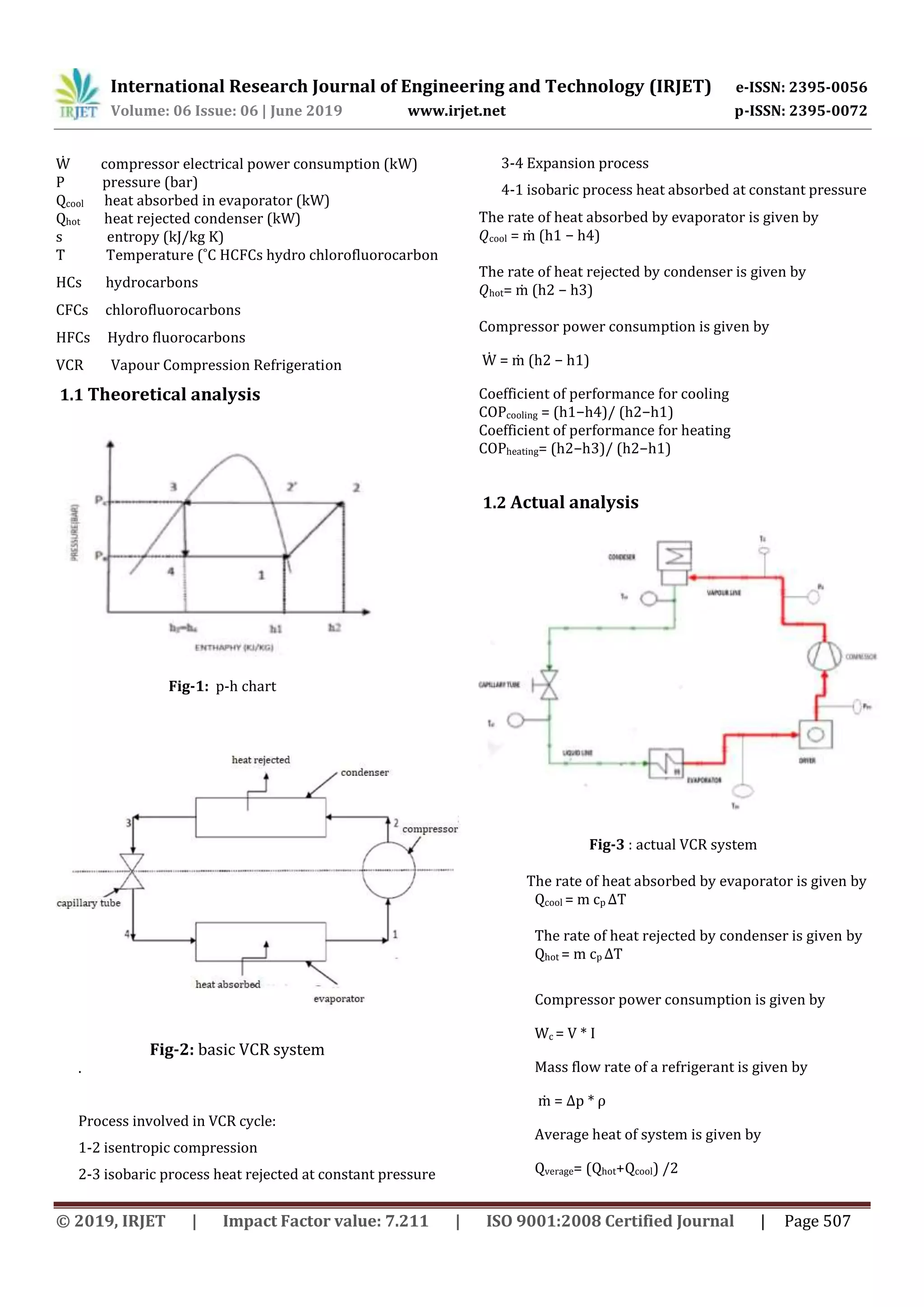
Nomenclature
COP coefficient of performance
Cp specific heat at constant pressure (kJ/kg K)
h enthalpy (kJ/kg)
ṁ mass flow rate (kg/s)](https://image.slidesharecdn.com/irjet-v6i6113-191109105302/75/IRJET-Design-and-Fabrication-of-Simultaneous-Heating-and-Cooling-in-VCR-System-using-R134A-Refrigerent-1-2048.jpg)
![International Research Journal of Engineering and Technology (IRJET) e-ISSN: 2395-0056
Volume: 06 Issue: 06 | June 2019 www.irjet.net p-ISSN: 2395-0072
© 2019, IRJET | Impact Factor value: 7.211 | ISO 9001:2008 Certified Journal | Page 512
Compressor power consumption is given by
Wc = V * I
=230 * 0.45
= 103.5
Coefficient of performance of cooling
COPcooling = Qcoo l / ( Qhot - Qcool)
= 4.69 / (12.194-4.69)
=0.625
Coefficient of performance of heating
COPheating = Qhot / ( Qhot - Qcool)
= 12.194 / (12.194-4.69)
=1.625
EERcool = COPcooling * 3.5
= 0.625 * 3.5
= 2.1875
EERhot = COPheating * 3.5
= 1.625 * 3.5
= 5.6875
Average heat of system is given by
Qverage= (Qhot+Qcool) /2
QAverage = (12.194 + 4.69) / 2
= 8.442
Coefficient of performance
COP = Qverage / Wc
= 8.442 / 103.5 = 0.08156
8) RESULT
1. COPcooling = 0.625
2. COPheating = 1.625
3. COPsystem = 0.08156
3. CONCLUSIONS
Performance evaluation ofsimultaneousheatingandcooling
in vapor compression refrigeration system usingR134a was
studied. By using simultaneous heating and cooling, wesave
the Hugh amount of electricity and save the initial cost of
extra equipment. We achieve hot water in low cost and in
less time. R134a is eco-friendly refrigerant, it has zero ODP
and low GWP. We can use this system in food process
industry, and hot water for bathing, washing cloth and pot
performance of R134a is good, but for further improvement
the. Different refrigerant can be studied. In future, we will
use R600a, R290 and R152 for research to achieve high
coefficient of performance.
REFERENCES
[1] V. Subash, “PERFORMANCE ANALYSIS OF VAPOUR
COMPRESSION REFRIGERATION SYSTEM USING
MIXED REFRIGERANTS OFR134A and R404A,” pp.
17–20, 2016.
[2] S. K. Bandey, “A study on refrigerants,” pp. 4287–
4293, 2018.
[3] B. Talekar, A. Barve, and R. Jangam, “Design &
Fabrication of Vapour Compression Refrigeration
System Test Rig,” vol. 7, no. 6, pp. 1414–1418, 2018.
[4] D. Paliwal and S. P. S. Rajput, “A Review on
Refrigerants , And Effects on Global Warming For
Making Green Environment,” vol. 12, no. 2, pp. 8–11,
2015.
[5] A. C. Tiwari and S. Barode, “Performance Analysis of
Vapour Compression Refrigeration Systems Using
Hydrofluorocarbon Refrigerants,” vol. 3, no. 12, 2012.
[6] S. Khansaheb, “A Review on Domestic Refrigerator
Using Hydrocarbons as Alternative Refrigerants to,”
pp. 536–541, 2015.
[7] R. Kumar, “Performance Analysis of Household,” vol. 3,
no. 4, pp. 11397–11405, 2014.
[8] R. S. Powade, A. A. Rane, A. D. Rane, O. S. Sutar, and V.
S. Bagade, “Performance Investigation of
Refrigerants R290 and R134a as an Alternative to
R22,” vol. 6, no. Iv, pp. 4668–4676, 2018.
[9] K. Nagalakshmi and G. M. Yadav, “The Design and
Performance Analysis of Refrigeration System Using
R12 & R134a Refrigerants,”vol.4,no.2,pp.638–643,
2014.
[10] B. Talekar, A. Barve, and R. Jangam, “Design &
Fabrication of Vapour Compression Refrigeration
System Test Rig,” vol. 7, no. 6, pp. 1414–1418, 2018
[11] V. Subash, “PERFORMANCE ANALYSIS OF VAPOUR](https://image.slidesharecdn.com/irjet-v6i6113-191109105302/75/IRJET-Design-and-Fabrication-of-Simultaneous-Heating-and-Cooling-in-VCR-System-using-R134A-Refrigerent-7-2048.jpg)
![International Research Journal of Engineering and Technology (IRJET) e-ISSN: 2395-0056
Volume: 06 Issue: 06 | June 2019 www.irjet.net p-ISSN: 2395-0072
© 2019, IRJET | Impact Factor value: 7.211 | ISO 9001:2008 Certified Journal | Page 513
COMPRESSION REFRIGERATION SYSTEM USING
MIXED REFRIGERANTS OFR134A and R404A,” pp.
17–20, 2016
[12] R. K. Rajput reference book
[13] P. K. Nag reference book
BIOGRAPHIES
Professor, Dept. of Mechanical
Engineering, Dr. D Y Patil Institute
Of Engg. Management & Research,
Akurdi Pune
B.E. Mechanical engineer at Dr. D Y
Patil Institute Of Engg. Management
& Research, Akurdi Pune](https://image.slidesharecdn.com/irjet-v6i6113-191109105302/75/IRJET-Design-and-Fabrication-of-Simultaneous-Heating-and-Cooling-in-VCR-System-using-R134A-Refrigerent-8-2048.jpg)

This document describes the design and fabrication of a vapor compression refrigeration system that provides simultaneous heating and cooling using R134a refrigerant. The system utilizes the waste heat rejected in the condenser for purposes like heating water by using a water-cooled condenser. This eliminates the need for separate heating equipment and saves costs. The methodology involves selecting R134a as the environmentally friendly refrigerant, designing the water-cooled condenser and evaporator, integrating other system components, and evaluating the system parameters and performance. The main objective is to efficiently use the waste heat from the condenser for heating applications while providing cooling.


