Download to read offline
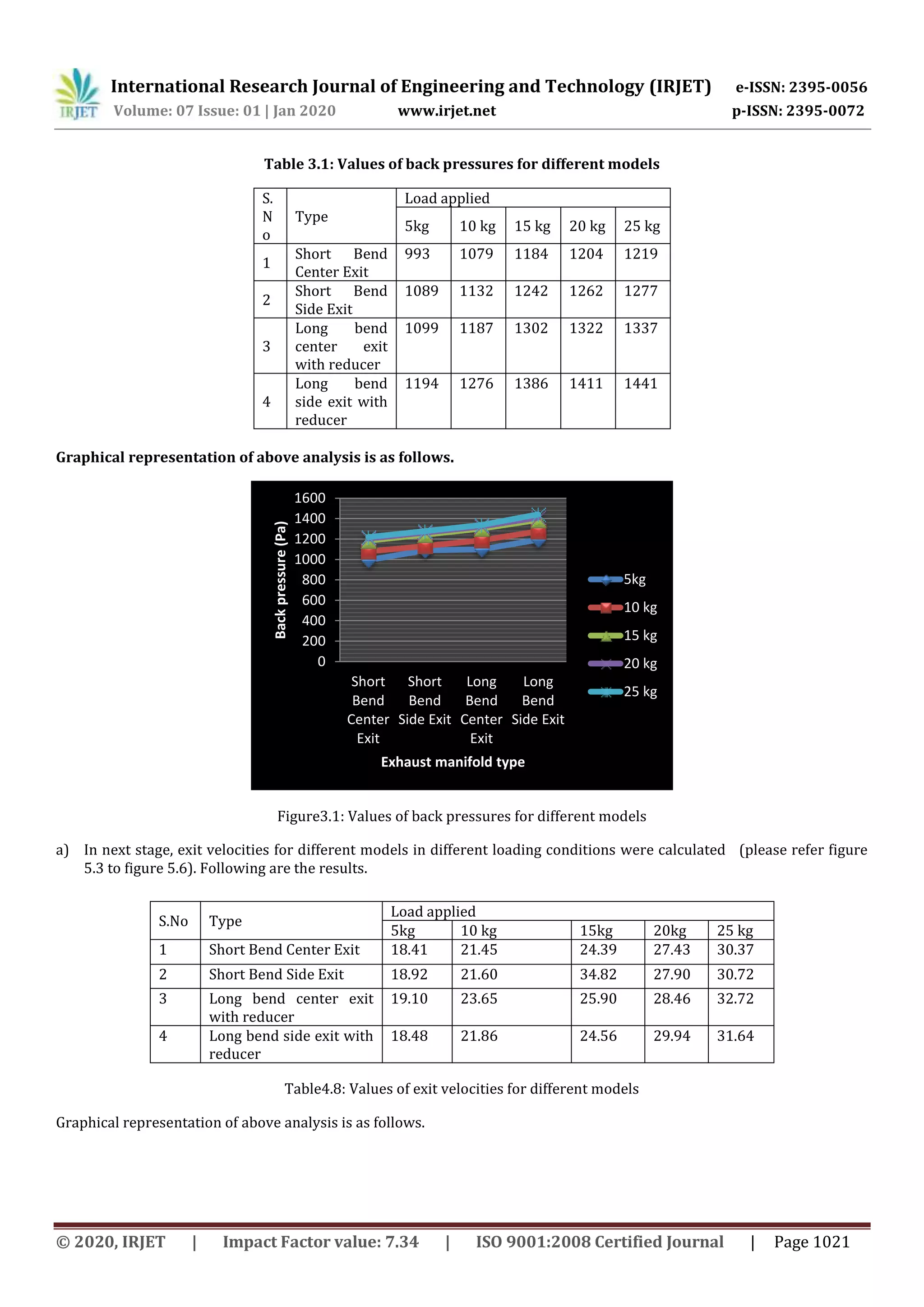
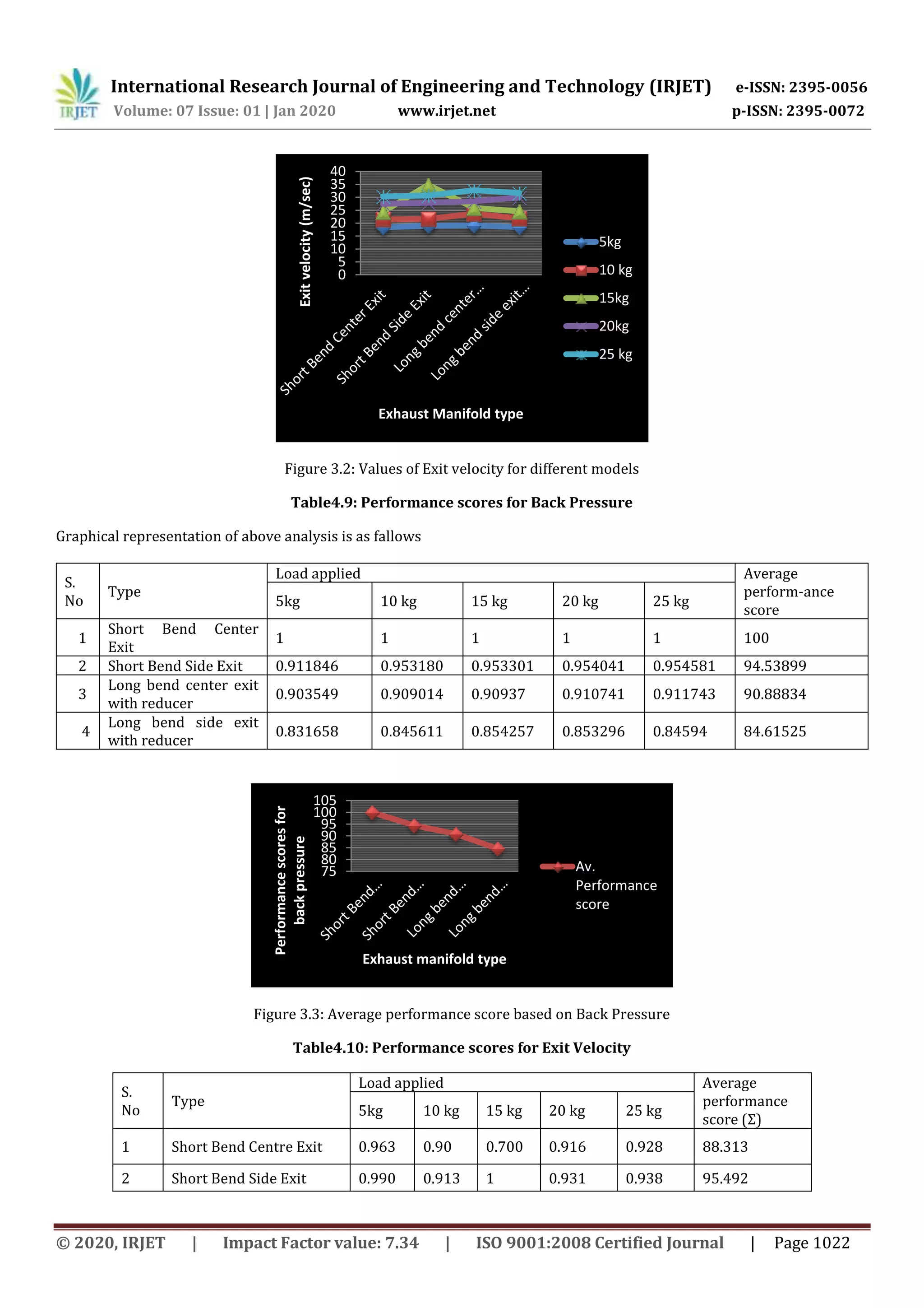
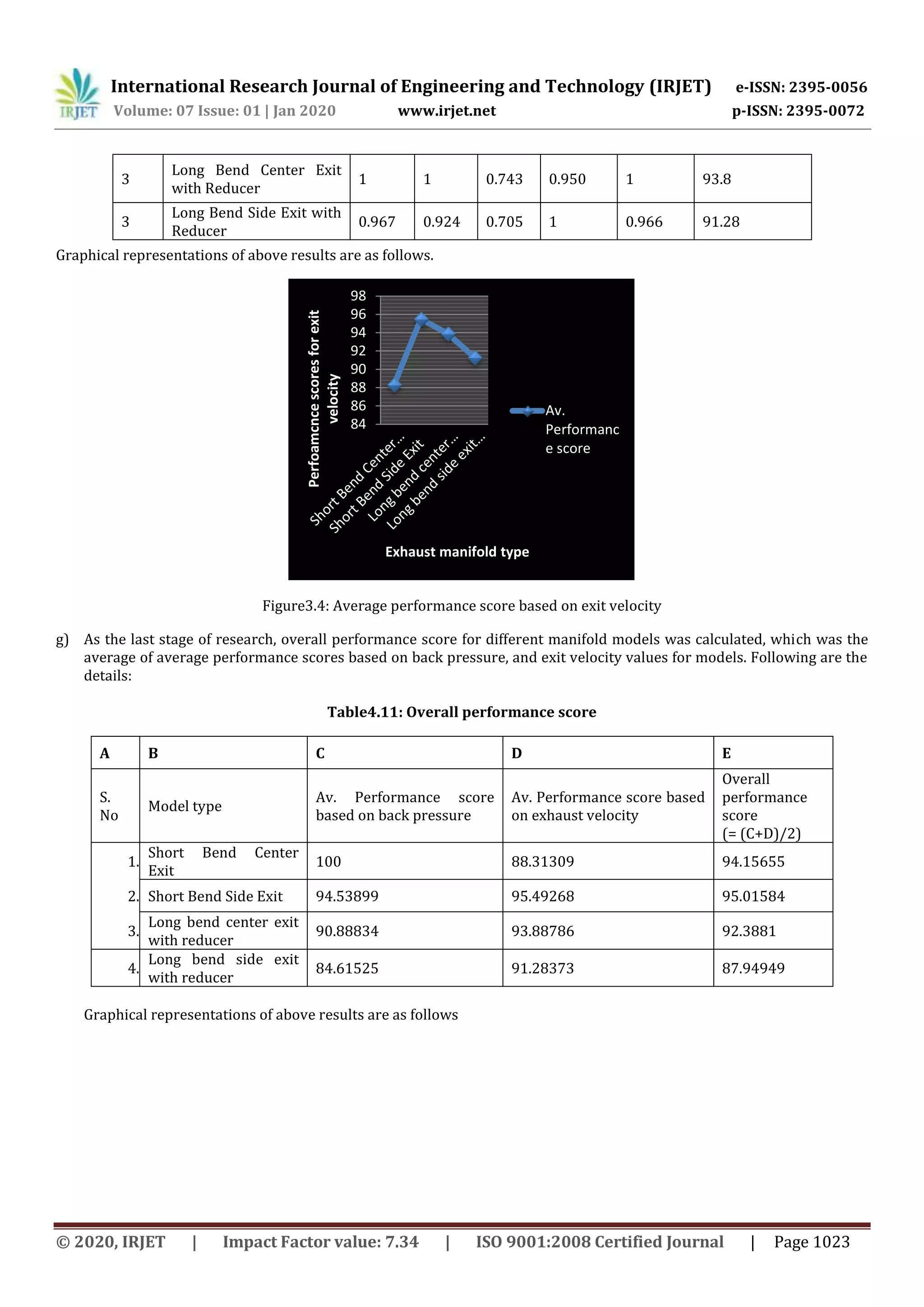
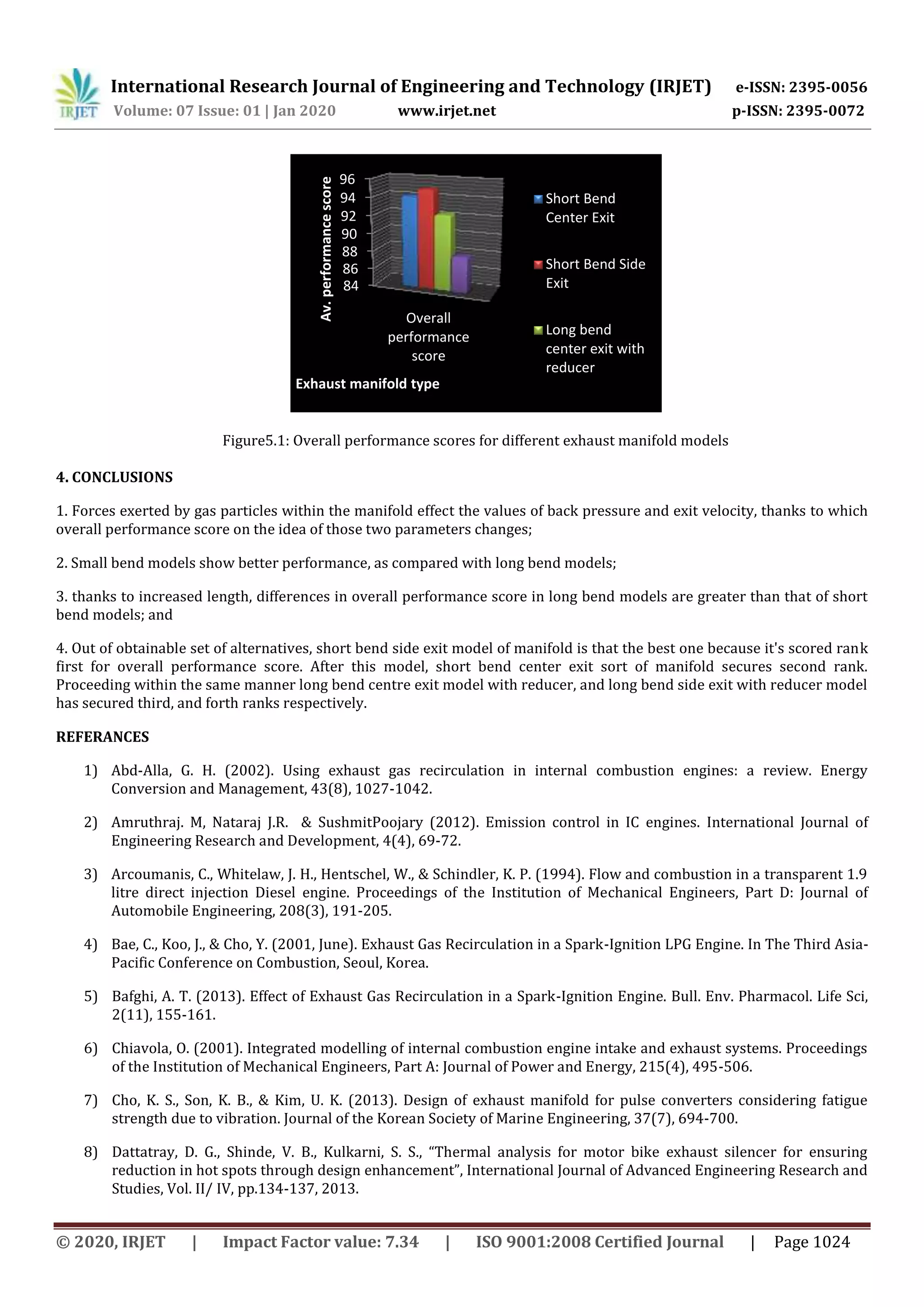

This document discusses modeling and analysis of different exhaust manifold designs for a multi-cylinder spark ignition engine to reduce emissions. Four exhaust manifold designs are considered: short bend center exit, short bend side exit, long bend center exit with reducer, and long bend side exit with reducer. The designs are modeled and analyzed using CATIA and ANSYS to evaluate back pressure and exhaust exit velocity under various loading conditions. The results show that the long bend center exit design with reducer has the lowest back pressure and highest exit velocity, indicating it is the optimal design for reducing emissions.


![(K 10619) krishna murari yadav [i.c. engine]](https://cdn.slidesharecdn.com/ss_thumbnails/k-10619krishnamurariyadavi-160510084637-thumbnail.jpg?width=640&height=640&fit=bounds)


