Download to read offline

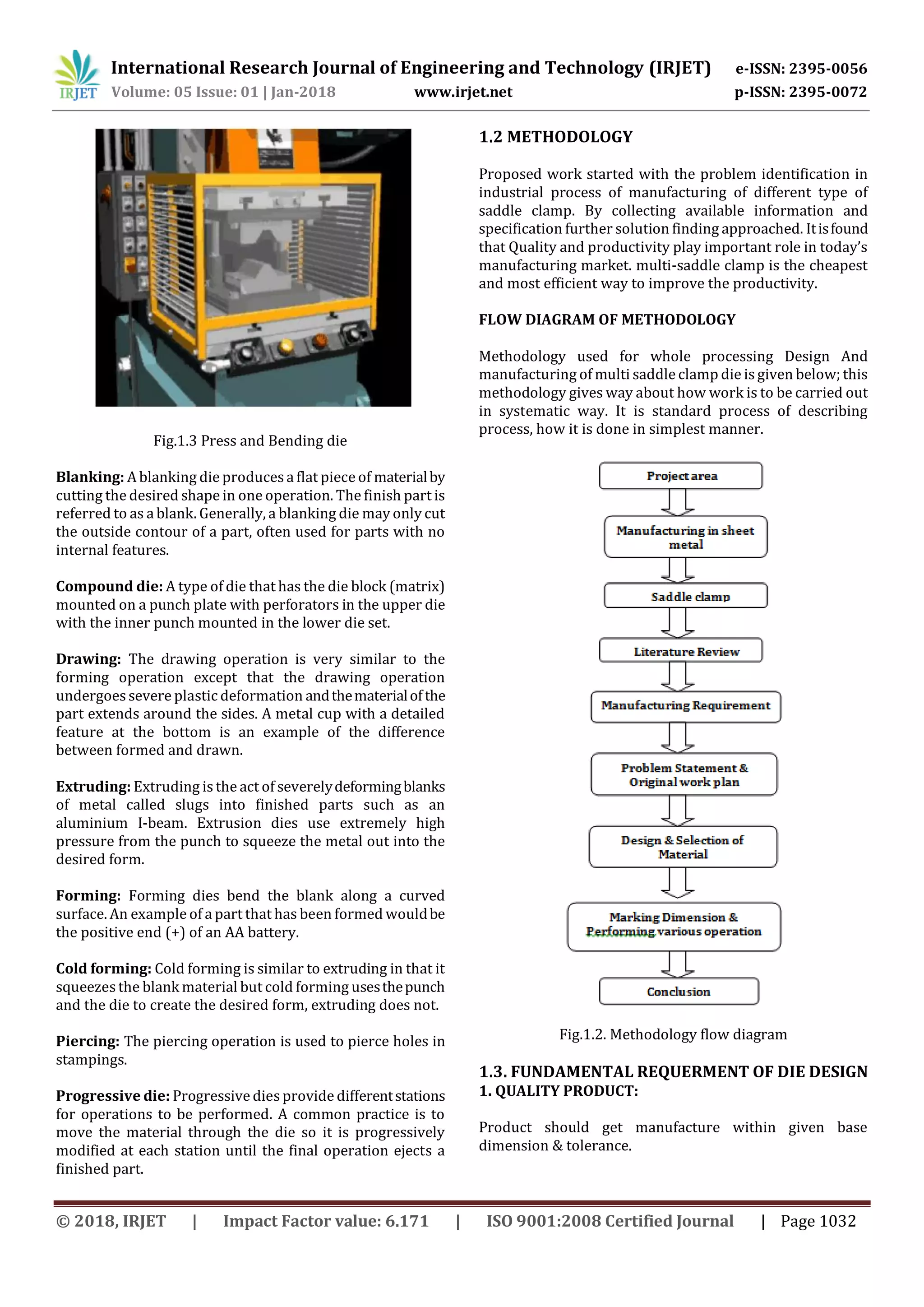
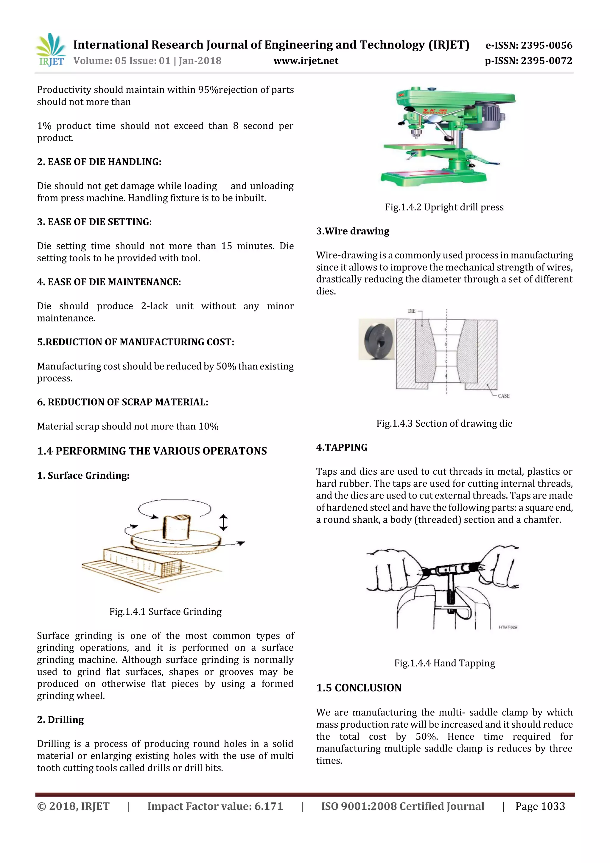


The document discusses the design and manufacturing of a multi-saddle clamp die. Previously, single cavity dies were used to manufacture individual saddle clamps through bending or blanking operations. However, this was an inefficient process. The proposed multi-saddle clamp die allows for multiple clamps to be manufactured simultaneously through bending and blanking operations in the same die, improving productivity. Key requirements for the die design include producing quality products efficiently while minimizing manufacturing costs and scrap material. The methodology involves identifying the problem, collecting information, and developing a solution to design a die that can manufacture multiple saddle clamps in a single cycle through different operations like surface grinding, drilling, tapping, and wire drawing.