Download to read offline


![IRC:SP:73-2018
6
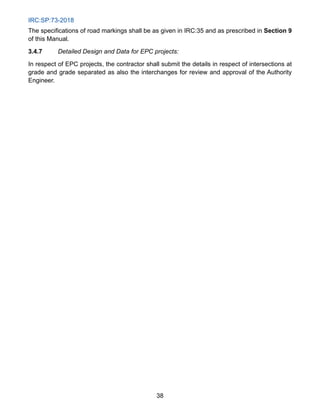
SECTION - 1
GENERAL
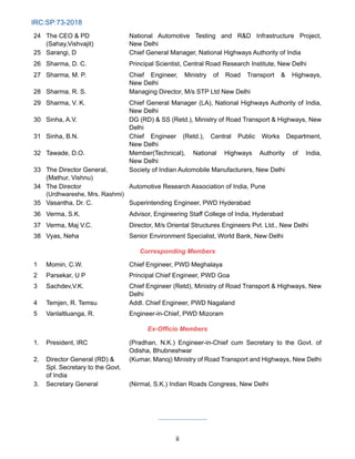
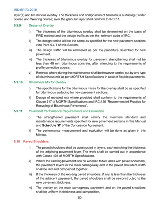
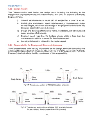
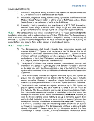
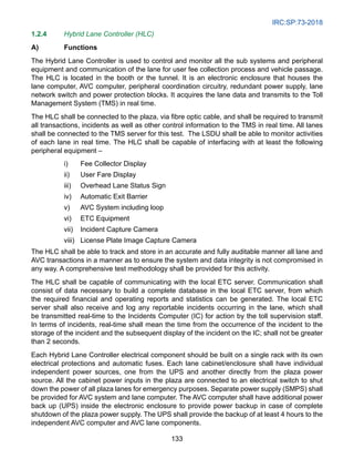
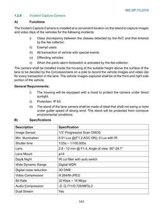
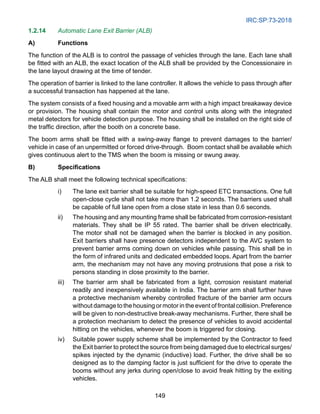
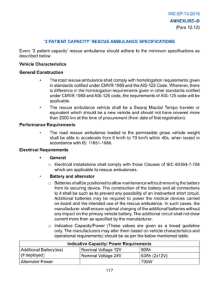
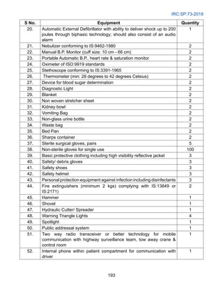
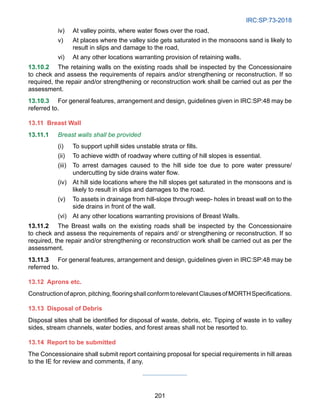
1.1 This Manual describes the planning, standards, design, construction, maintenance,
operation, safety and environmental requirements to be fulfilled in execution of the works of [ …]
under a concession or contract Agreement and shall be read harmoniously and in conjunction
with the contract. This Manual is applicable for Two Laning of Highways (with or without paved
shoulders) through Public Private Partnership (PPP), EPC or any other mode. The general
planning aspects laid out in this Manual shall be applicable for widening from single/intermediate
lane to two lane or new construction of two lane highways. The scope of the work shall be as
defined in the Concession Agreement. As far as National Highways are concerned, two laning
in this Manual shall mean two lane with paved shoulders as per Ministry’s Guidelines unless
otherwise specified.
1.2 The Project Highway and the project facilities shall conform to the requirements of design
and specifications set out in this Manual, which are the minimum prescribed. The project report
and other information provided by the Authority shall be used by the Concessionaire only for its
own reference and for carrying out further investigations. The Concessionaire shall be solely
responsible for undertaking all the necessary surveys, investigations and detailed designs in
accordance with Authority for any loss, damage, risk, costs, liabilities or obligations arising out of
or in relation to the project report and other information provided by the Authority.
1.3 At least 2 weeks prior to commencement of the work, the Concessionaire shall draw up
a Quality Assurance Manual (QAM) covering the Quality System (QS), Quality Assurance Plan
(QAP) and documentation for all aspects of the bridge and road works, which shall include the
standard operative procedures which the Concessionaire, his personnel, his contractors and their
sub-contractors shall follow during execution and send three copies of each to the Independent
Engineer (IE) for review. The class of quality assurance shall be as per IRC:SP:112-2017 Manual
for Quality Control in Road and Bridge Works.
1.4 The Codes, Standards, Technical Specifications and Guidelines applicable for the design
and construction of project components are:
i) Indian Roads Congress (IRC) Codes, Standards and Guidelines;
ii) Specifications for Road and Bridge Works issued by the Ministry of Road
Transport Highways (MORTH) hereinafter referred to as MORTH or Ministry’s
specifications.
iii) Any other standards referred to in the Manual and any supplement issued
with the bid document.
1.5 The version of the Codes, Standards, Specifications, etc. notified/published at least 60
days prior to the last date of bid submission shall be considered applicable.](https://image.slidesharecdn.com/irc-230519121254-c789ba91/85/irc-073-2018-document-uploaded-by-Priyanshu-Kumar-9608684800-16-320.jpg)


![IRC:SP:73-2018
116
of the Toll Plazas shall not be removed. The installation of Medium Speed Weigh
in Motions (MSWIMs) shall be carried out only on those lanes where there is no
existing Weigh in Motion (WIM) equipment / hardware.
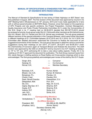
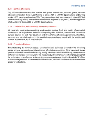
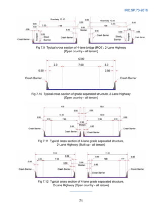
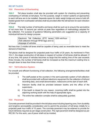
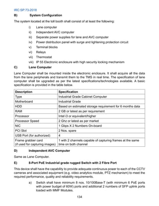
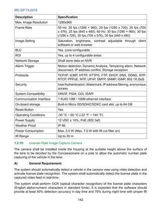
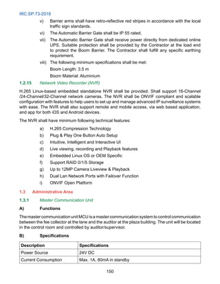
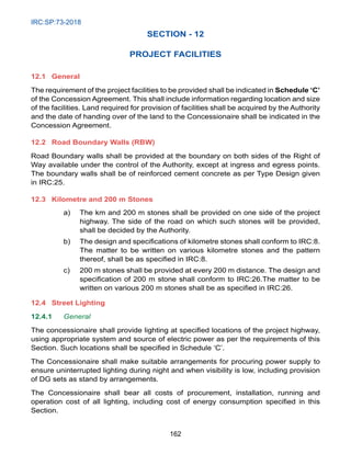
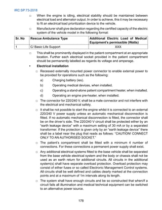
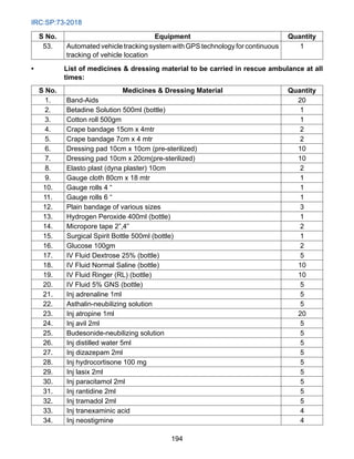
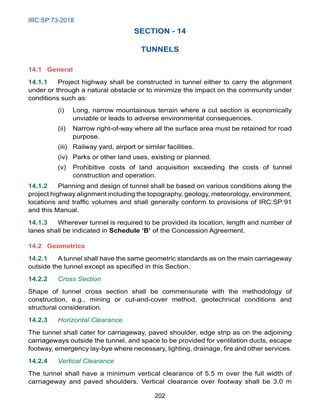
10.5.4 Service Level
i) The uptime availability of all critical components of Hybrid ETC lanes shall be
99% per lane per month for 90% of total lanes in a toll plaza (rounded off to
nearest integer). For the balance 10% lanes, uptime availability of all critical
components shall be 98% per lane per month.
ii) The downtime for a toll lane shall be calculated at a cumulative level when any
of the below mentioned critical component is non-operational for that specific
lane:
a) ETC RFID transceiver
b) Automatic Lane Barrier
c) Lane Incident Camera
d) Automatic Vehicle Classifier
e) Hybrid Lane Controller
f) Any other plaza level or lane level equipment leading to disruption in ETC
transactions
iii) For all other components of Hybrid ETC System, the uptime availability shall be
98% per lane per month.
iv) Scheduled downtime is defined as a period of time when system will remain
unavailable for conducting necessary preventive maintenance, urgent repairs
etc. The maximum scheduled downtime for any Site shall be 4 hours per lane
per month.
v) The formula for calculation of Hybrid ETC System availability shall be as follows:
System Uptime = [1-{A/(B-C)}*100]
Where A = Time for which system is down per month basis scenarios identified
in clause 4B
B = Total time in a month
C = Scheduled downtime basis Clause 4D
vi) The Concessionaire shall maintain adequate inventory to ensure the service
levels prescribed in Clause 4A are adhered. Spares of critical components
of Hybrid ETC System as identified in Clause 4B for at most 2 lanes shall be
included in the cost of change in Scope of Work Order. There shall be no other
provision or payment for additional Hybrid ETC equipment/hardware from the
Authority.
vii) The Concessionaire shall ensure that the Hybrid ETC Systems are operational
as per the service levels defined in Clause A to facilitate payment of user fee
through ETC. In case, a vehicle user with a valid, functional ETC RFID tag with
sufficient balance in the linked account is not able to pay user fee through ETC](https://image.slidesharecdn.com/irc-230519121254-c789ba91/85/irc-073-2018-document-uploaded-by-Priyanshu-Kumar-9608684800-126-320.jpg)
![IRC:SP:73-2018
117
through any lane owing to malfunctioning of Hybrid ETC equipment/hardware,
the vehicle user shall be permitted to pass without payment of any user fee.
viii) In case of non-adherence to service levels as defined in Clause 4A, suitable
damages shall be levied on each lane by the Authority over and above the free
passage of user as described in Clause 4G.
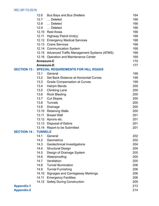
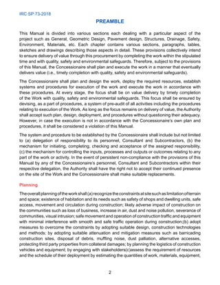
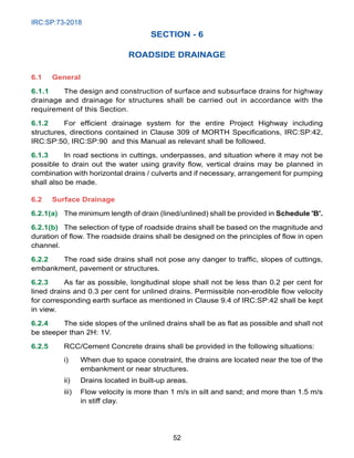
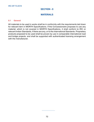
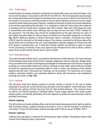
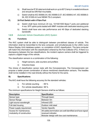
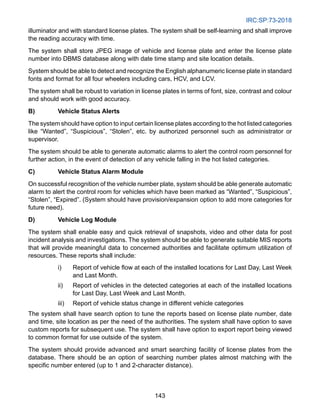
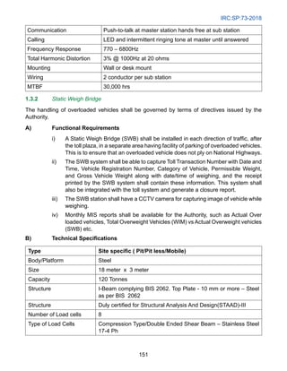
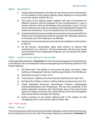
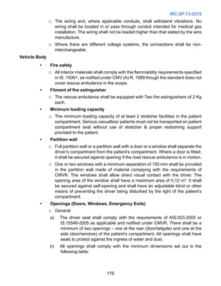
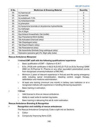
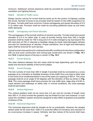
ix) The Concessionaire shall ensure that all transaction files are uploaded as per
defined service levels provided by the Authority or CCH. The service levels are
prescribed in the table below:
S. No. Description Service Level Damages
1. Sending clean
transaction files in a
specified format to
CCH
•
Within 10
minutes of [ETC
transaction]
•
Up to 3 days of
[ETC transaction.]
•
Transaction post 10 minutes shall
be processed only if the tag account
has sufficient balance. In case of
negative balance, the transaction
shall be rejected.
•
Liability of such transactions (after
10 minutes and before 3 days) shall
lie with the Concessionaire.
Transaction shall be rejected by CCH
after 3 days.
2. Sending violation
transactions post audit
at plaza level along
with clear supporting
images to CCH.
The images should be
clear enough to identify
the vehicle class.
•
Within 10 minutes
of ETC transaction
•
Up to 3 days of
ETC transaction
Transaction post 10 minutes shall be
processed only if the tag account has
sufficient balance. In case of negative
balance, the transaction shall be
rejected.
Liability of such transactions (after 10
minutes and before 3 days) shall lie
with the Concessionaire.
Transaction shall be rejected by CCH
after 3 days.
3. Populating blacklist
file in the Hybrid ETC
system of all the lanes.
•
Within 10 minutes
of receipt from
CCH
Post 10 minutes, any clean/violation
transaction file received by CCH for
the same tag account with inadequate
balance shall be rejected.
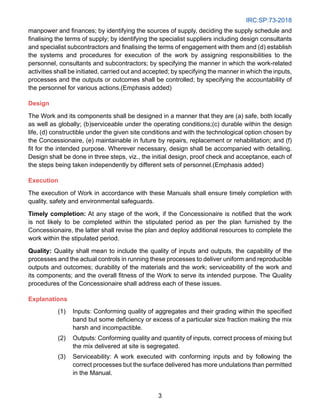
10.5.5 A) The Concessionaire shall be provided a list of Acquiring parties by the Authority
or a representative of the Authority amongst which the Concessionaire shall
select one for the processing of ETC transactions. The list of Acquiring parties
may be updated or modified from time to time by the Authority or a representative
of Authority and the Concessionaire shall abide by all the terms and conditions
of such directives.
B) The Concessionaire shall effect and maintain at its own cost, adequate
insurance cover for any case of accidental damage to Hybrid ETC Systems. The
Concessionaire shall indemnify the Authority against any claims whatsoever on
this account.](https://image.slidesharecdn.com/irc-230519121254-c789ba91/85/irc-073-2018-document-uploaded-by-Priyanshu-Kumar-9608684800-127-320.jpg)
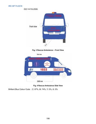


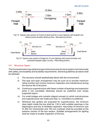
This document is the second revision of the Indian Roads Congress Manual of Specifications and Standards for Two Laning of Highways with Paved Shoulder, published in November 2018. It provides guidelines for geometric design, pavement structure, drainage, traffic control devices, safety works, and other aspects of two-lane highway projects. The manual contains 14 sections addressing topics such as intersections, road embankments, pavement design, drainage, structures, materials, and special requirements for hill roads and tunnels. It is intended to assist in planning, design, and execution of two-lane highway projects in India.


