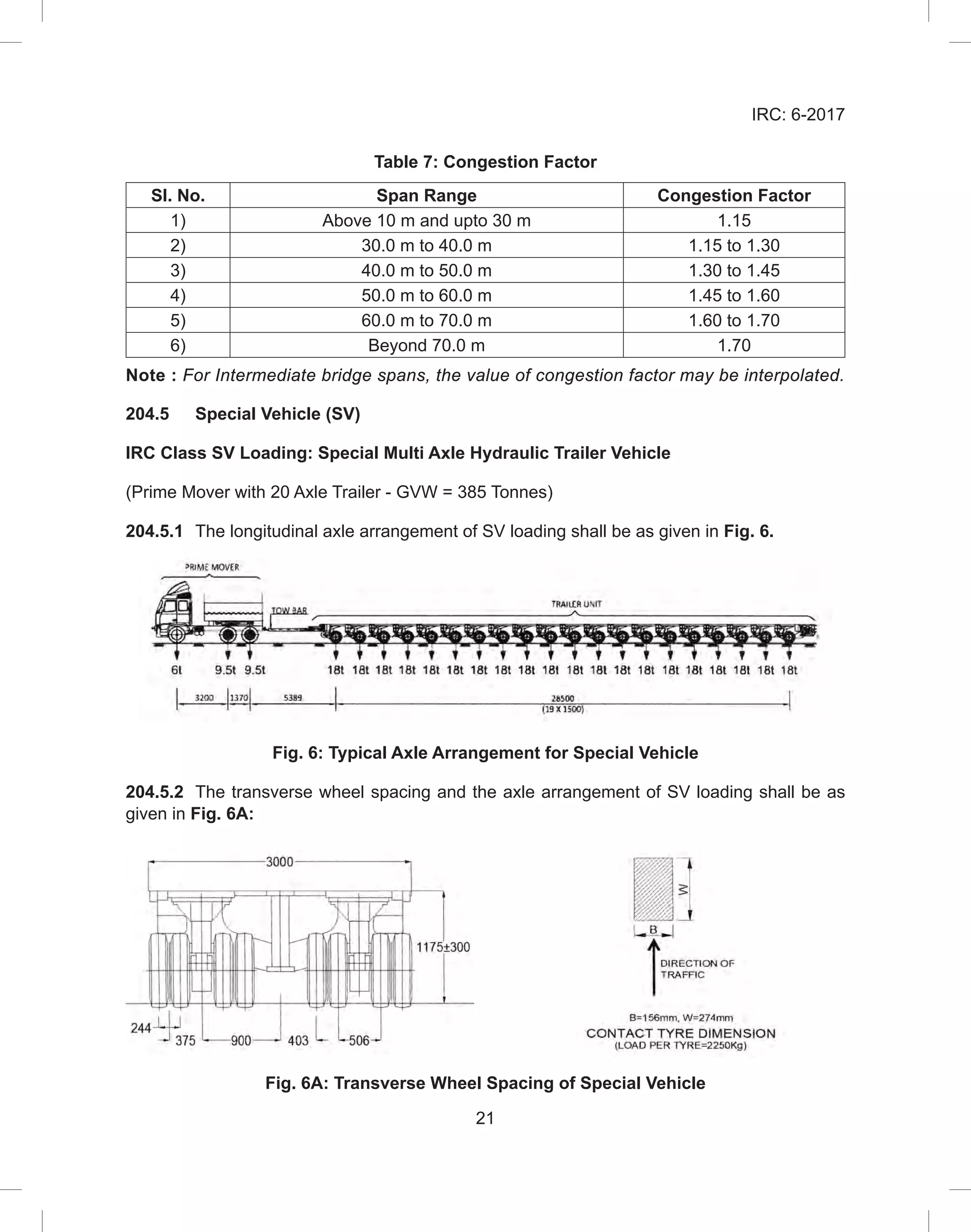
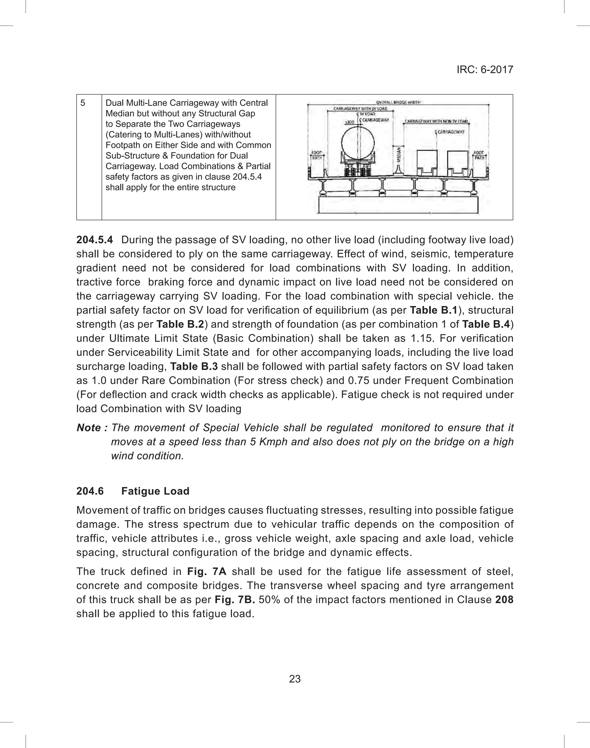
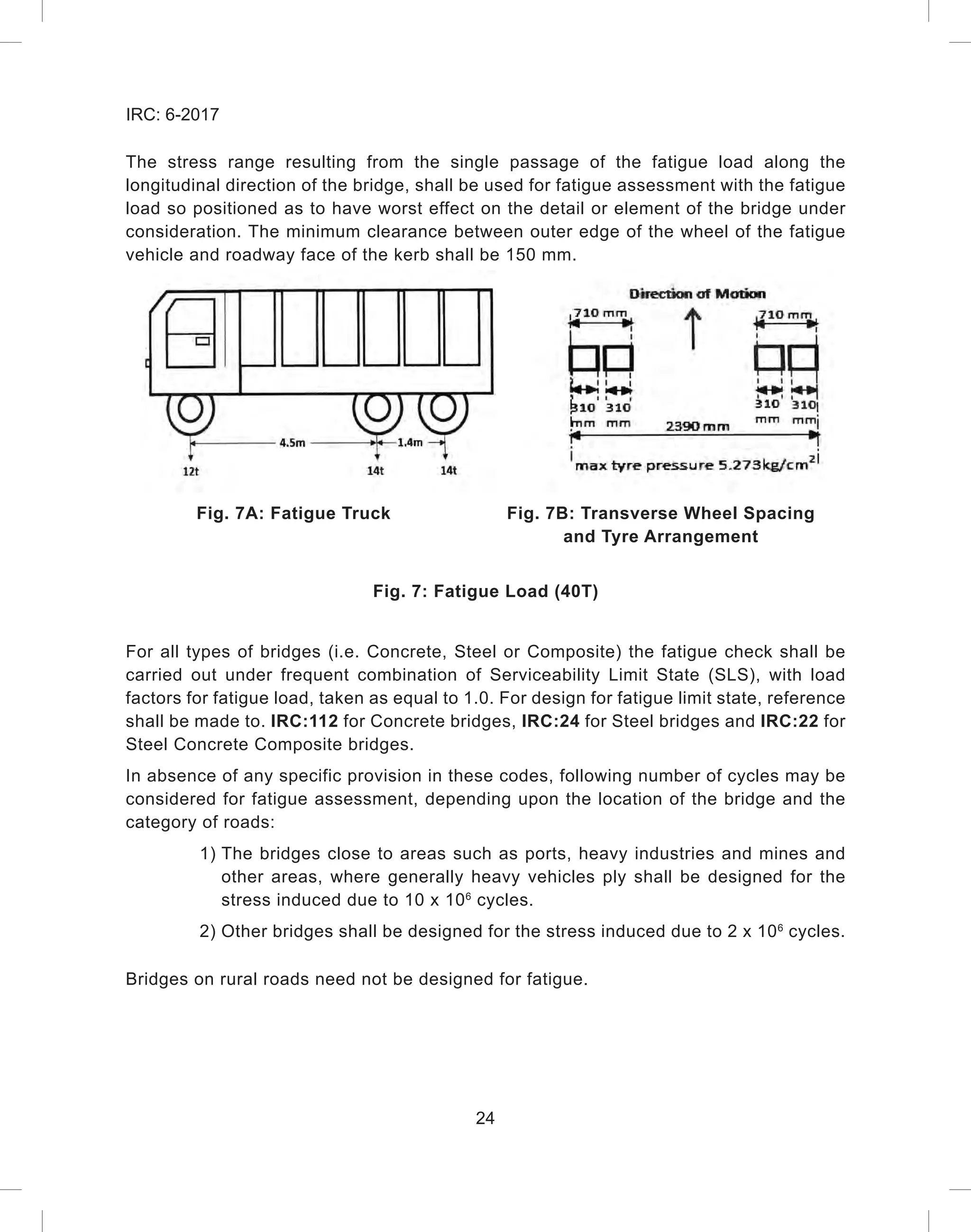
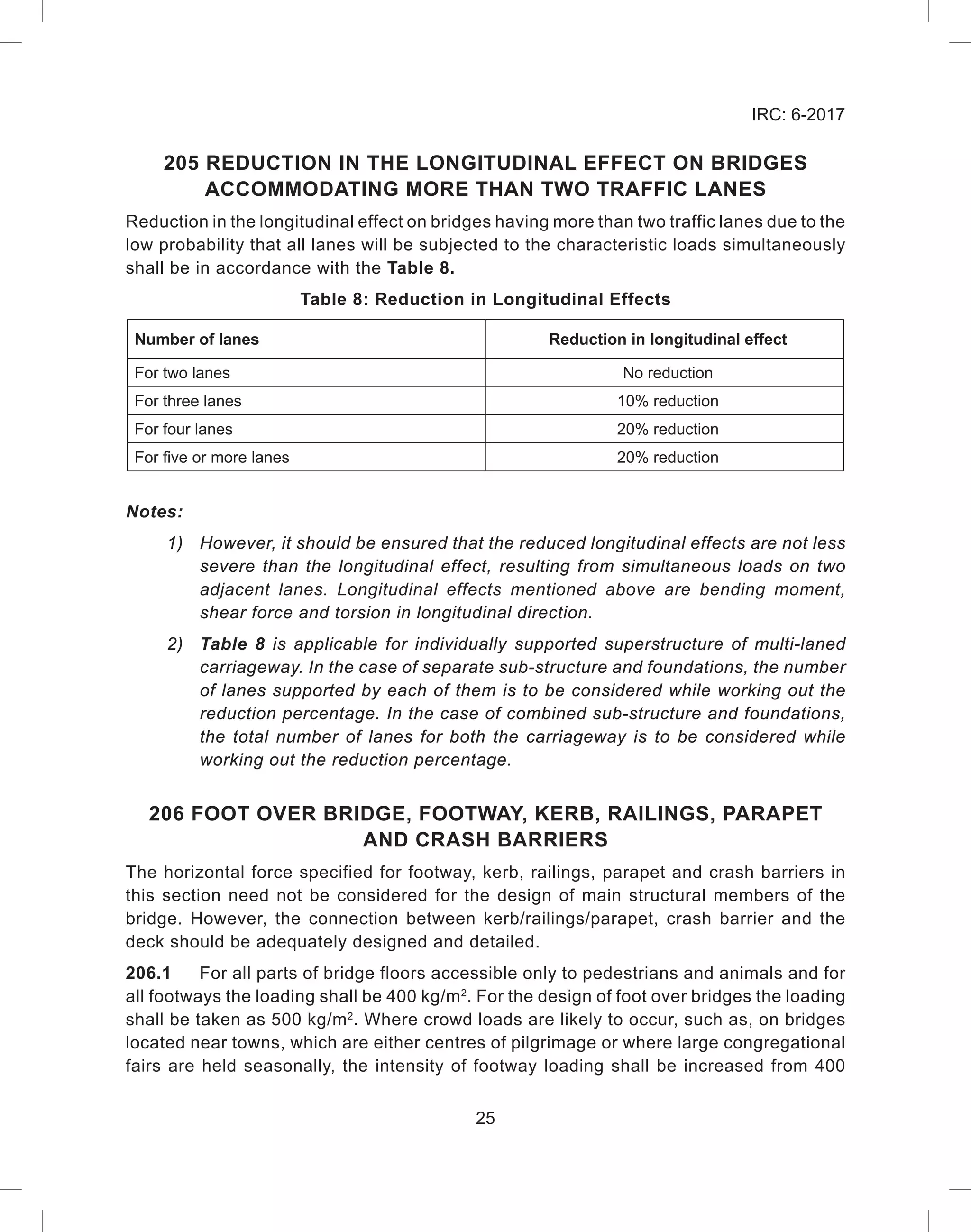
This document provides the 7th revision of Section II of the Indian Road Congress Standard Specifications and Code of Practice for Road Bridges, which covers Loads and Load Combinations. It summarizes the personnel of the Bridges Specifications and Standards Committee. It also briefly discusses the history and revisions of Section II. The objective of the code is to establish common procedures for design and construction of road bridges in India.


![13
IRC: 6-2017
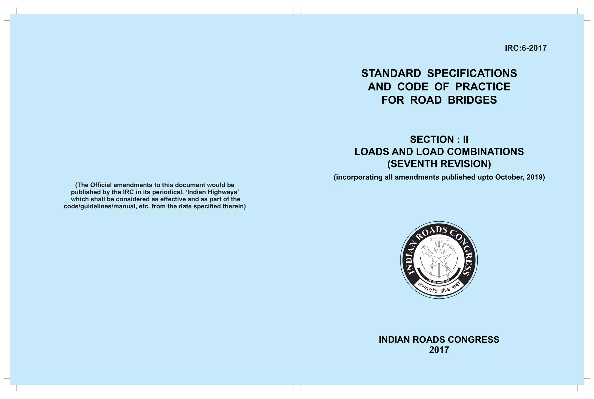
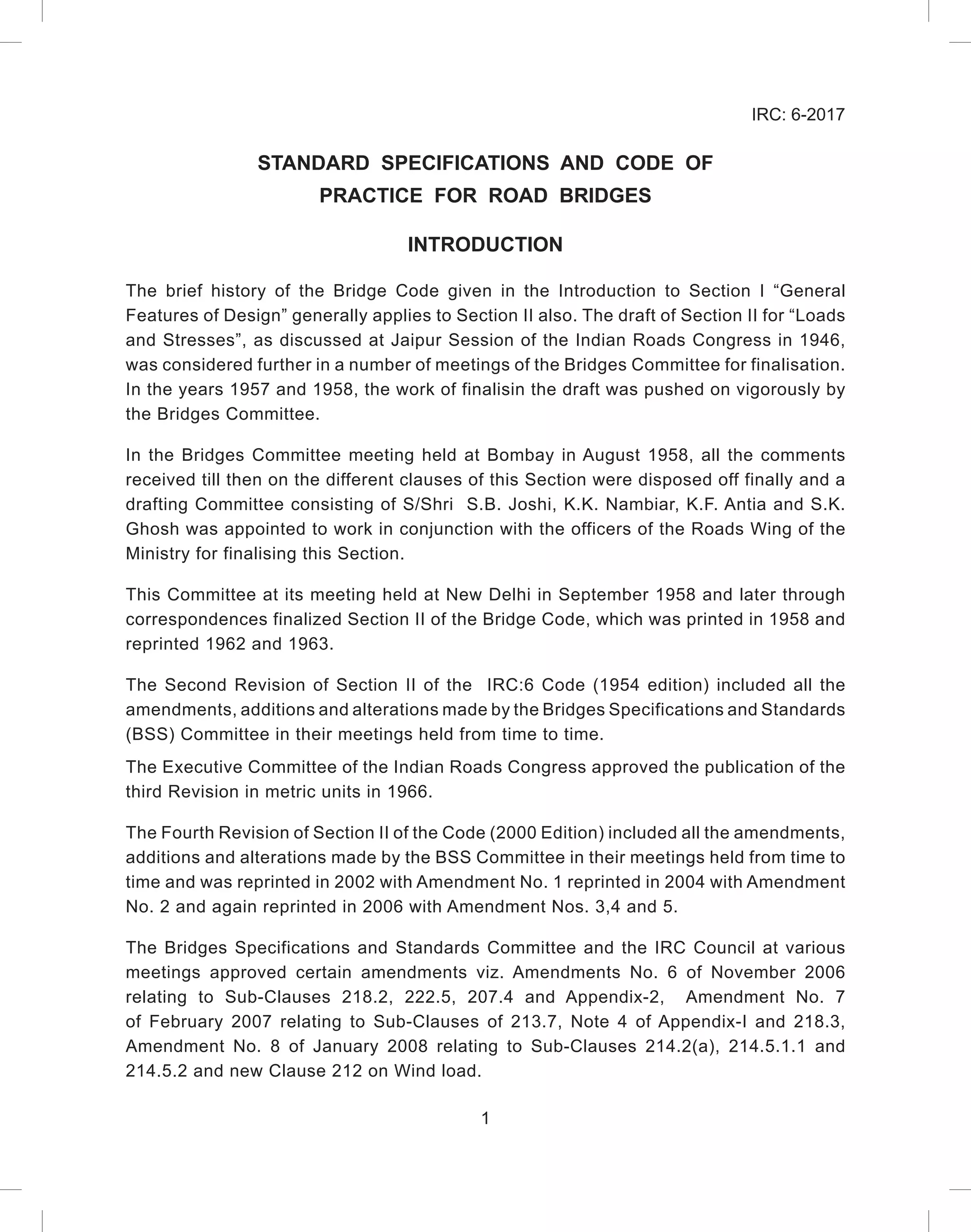
Table 2: Ground Contact Dimensions for Class A Loading
Axle load (tonne)
Ground contact area
B (mm) W (mm)
11.4 250 500
6.8 200 380
2.7 150 200
Fig. 3: Minimum Clearance for 2 Class A Train Vehicles
5)
The minimum clearance, f, between outer edge of the wheel and the roadway
face of the kerb and the minimum clearance, g, between the outer edges of
passing or crossing vehicles on multi-lane bridges shall be as given in Table 3.
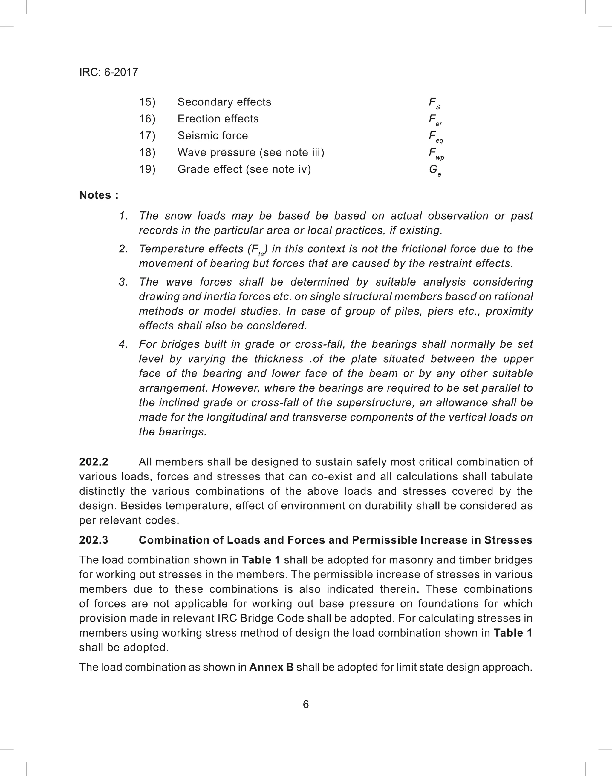
Table 3: Minimum Clearance for Class A Train Vehicle
Clear carriageway width g f
5.3 m(*) to 6.1 m(**)
Varying between 0.4 m to
1.2 m 150 mm for all
carriageway widths
Above 6.1 m 1.2 m
(*) = [2x(1.8+0.5)+0.4+2x0.15]
(**)= [2x(1.8+0.5)+1.2+2x0.15]
6) Axle loads in tonne. Linear dimensions in metre.
W W W W](https://image.slidesharecdn.com/irc-230429100357-30227d9f/75/irc-gov-in-006-2017-pdf-20-2048.jpg)
![15
IRC: 6-2017
Notes:
1)
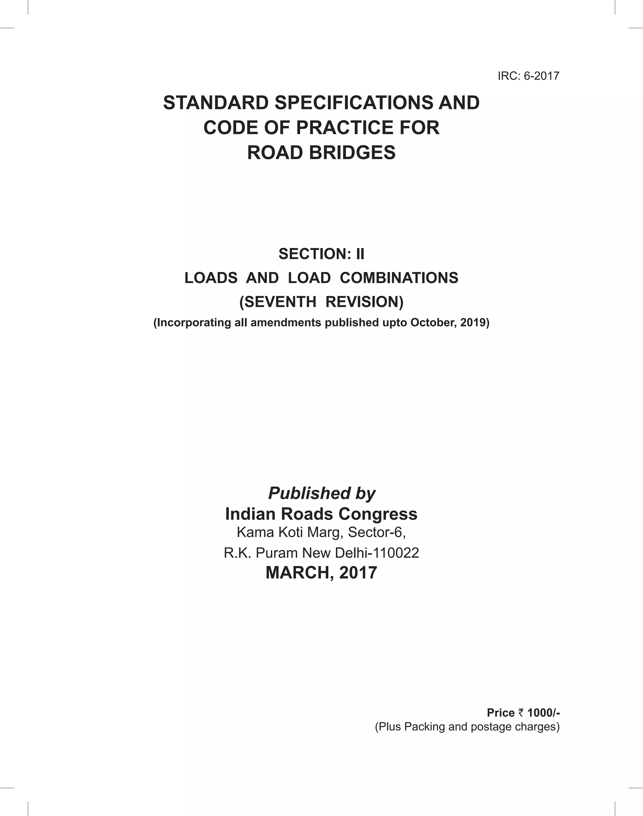
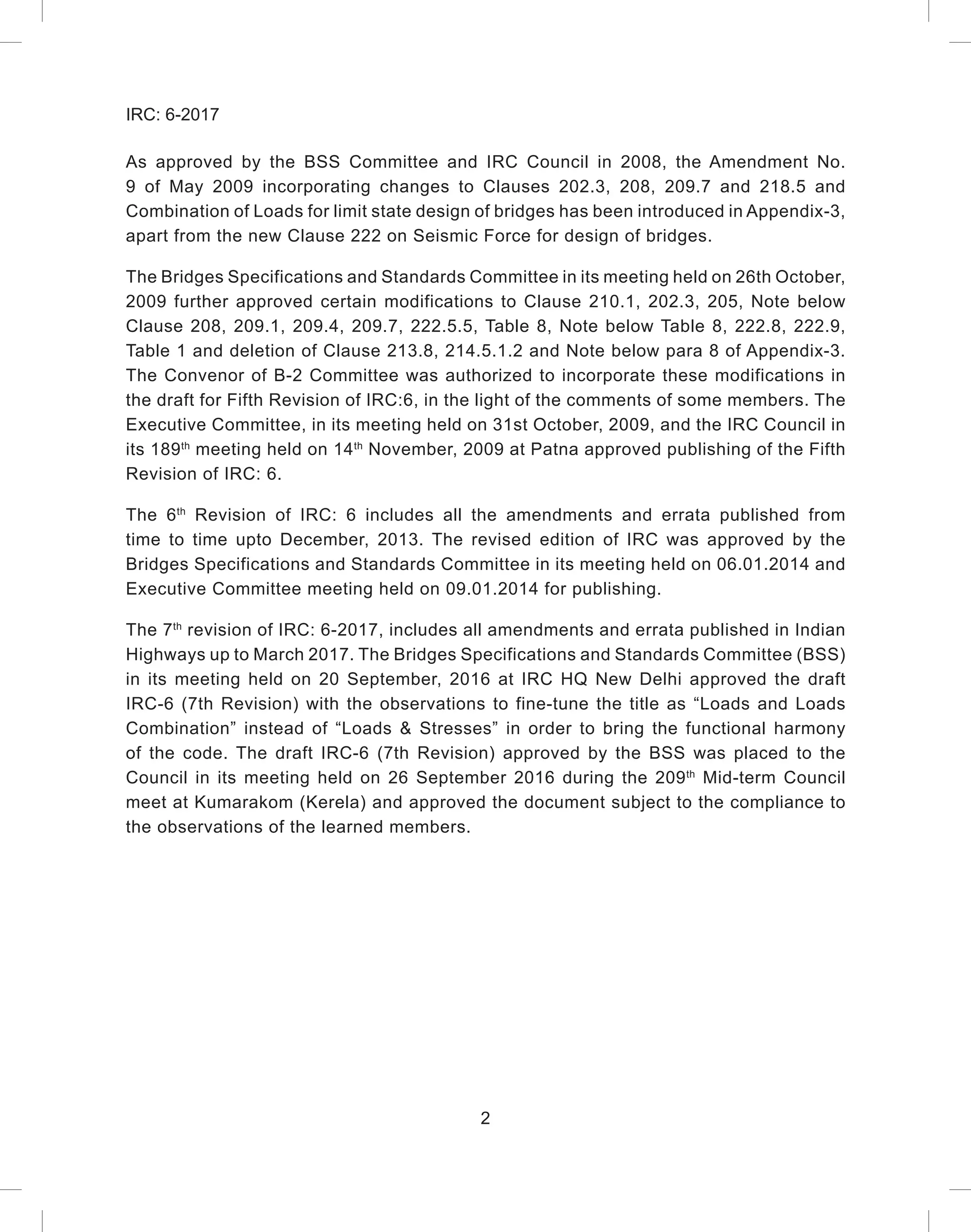
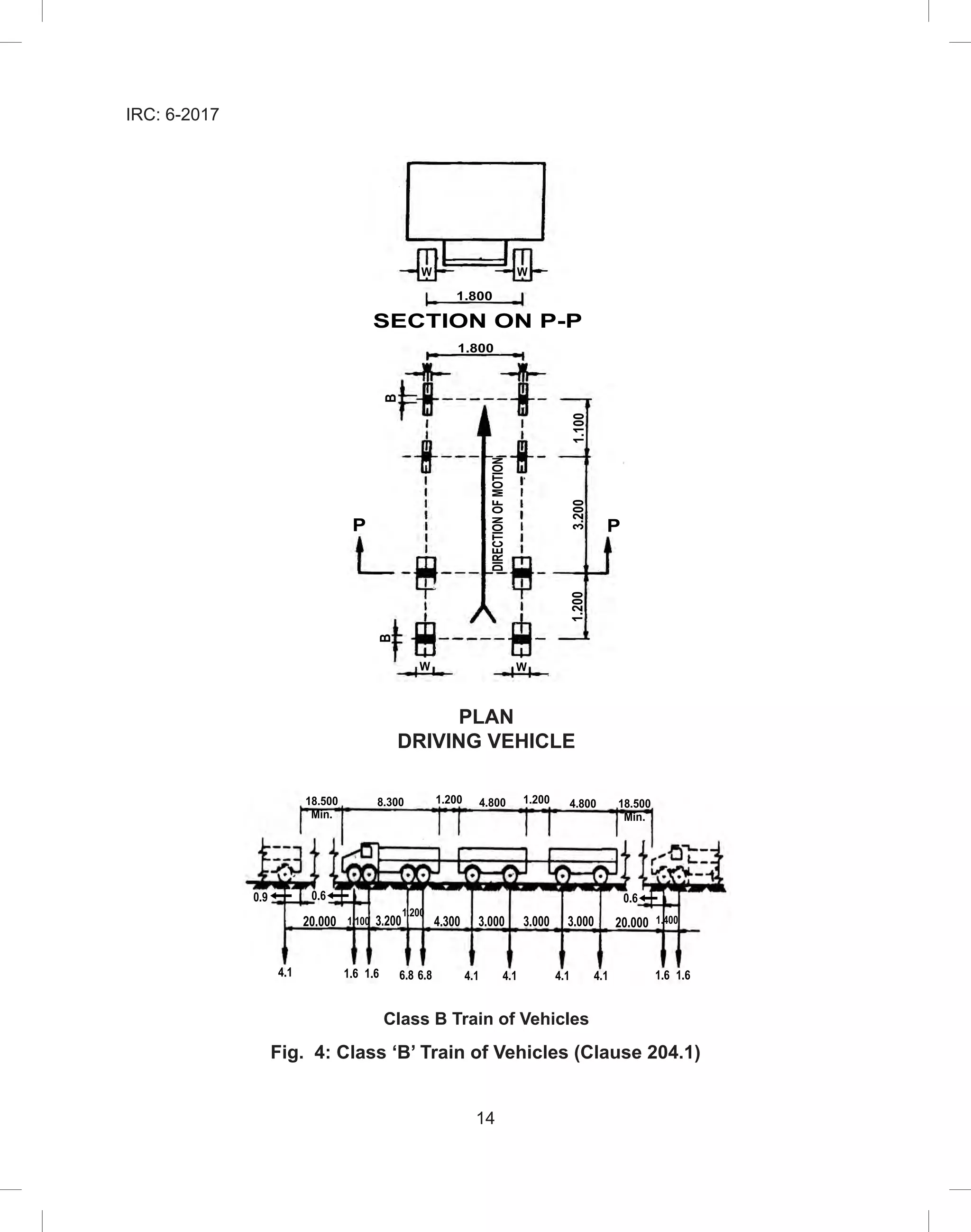
The nose to tail distance between successive trains shall not be less than 18.5 m.
2)
No other live load shall cover any part of the carriageway when a train of vehicles
(or trains of vehicles in multi-lane bridge) is crossing bridge.
3) The ground contact area of the wheels shall be as given in Table 4.
Table 4: Ground Contact Dimensions for Class B Loading
Axle load (tonne)
Ground contact area
B (mm) W (mm)
6.8 200 380
4.1 150 300
1.6 125 175
Fig. 5: Minimum Clearance for 2 Class B Train
4) For bridges having carriageway width less than 5.06 m, only single lane of Class B
loading shall be considered.
5)
The minimum clearances, f, between outer edge of the wheel and the roadway
face of the kerb and the minimum clearance, g, between the outer edges of
passing or crossing vehicles on multi-lane bridges shall be as given in Table 5
6) Axle loads in tonne. Linear dimensions in metre
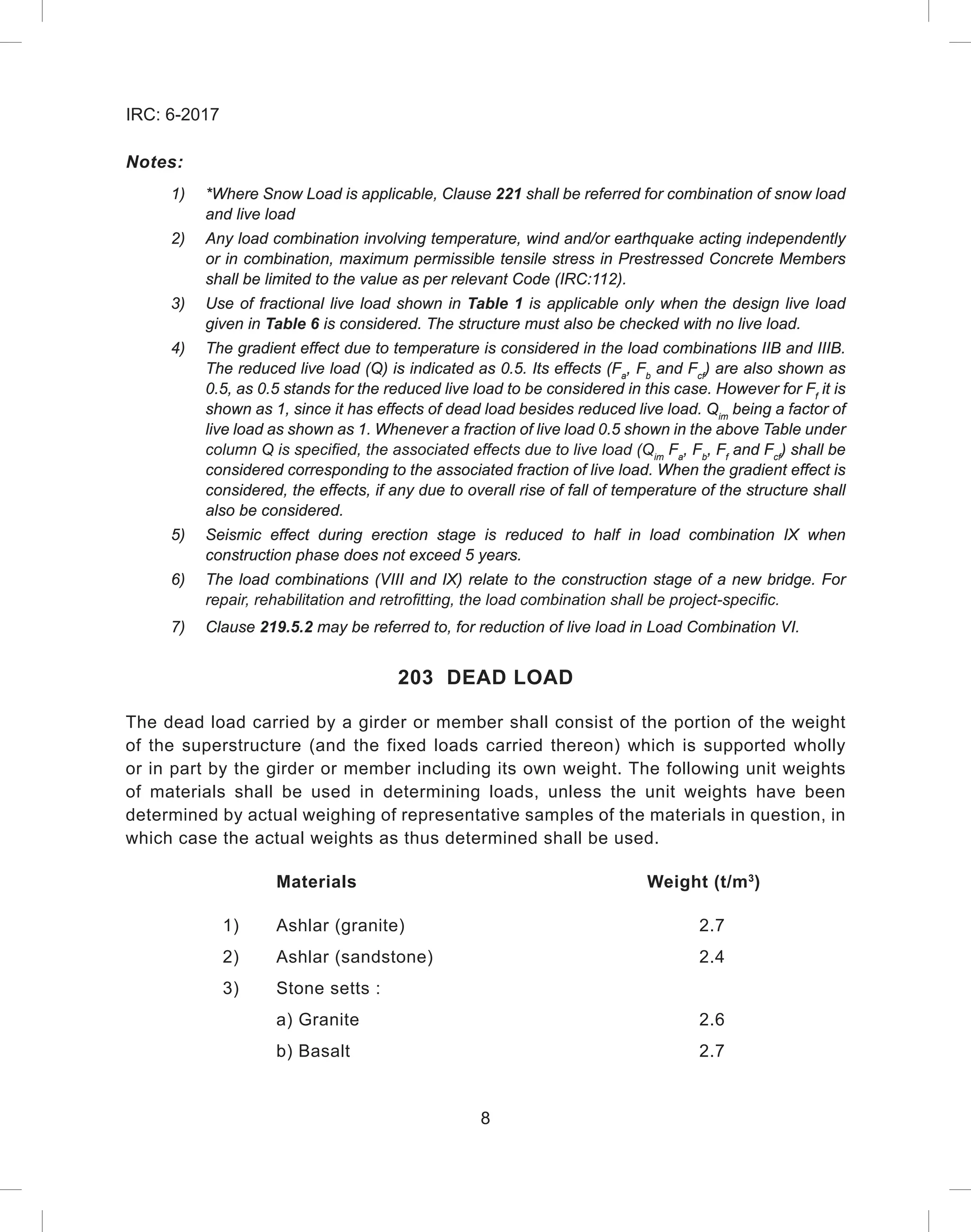
Table 5: Minimum Clearance for Class B Train
Clear carriageway width g f
5.06 m(*) to 5.86 m(**)
Varying between 0.4 m to
1.2 m 150 mm for all
carriageway widths
Above 5.86 m 1.2 m
(*) = [2x(1.8+0.38)+0.4+2x0.15]
(**)= [2x(1.8+0.38)+1.2+2x0.15]
W W W W](https://image.slidesharecdn.com/irc-230429100357-30227d9f/75/irc-gov-in-006-2017-pdf-22-2048.jpg)


![79
IRC: 6-2017
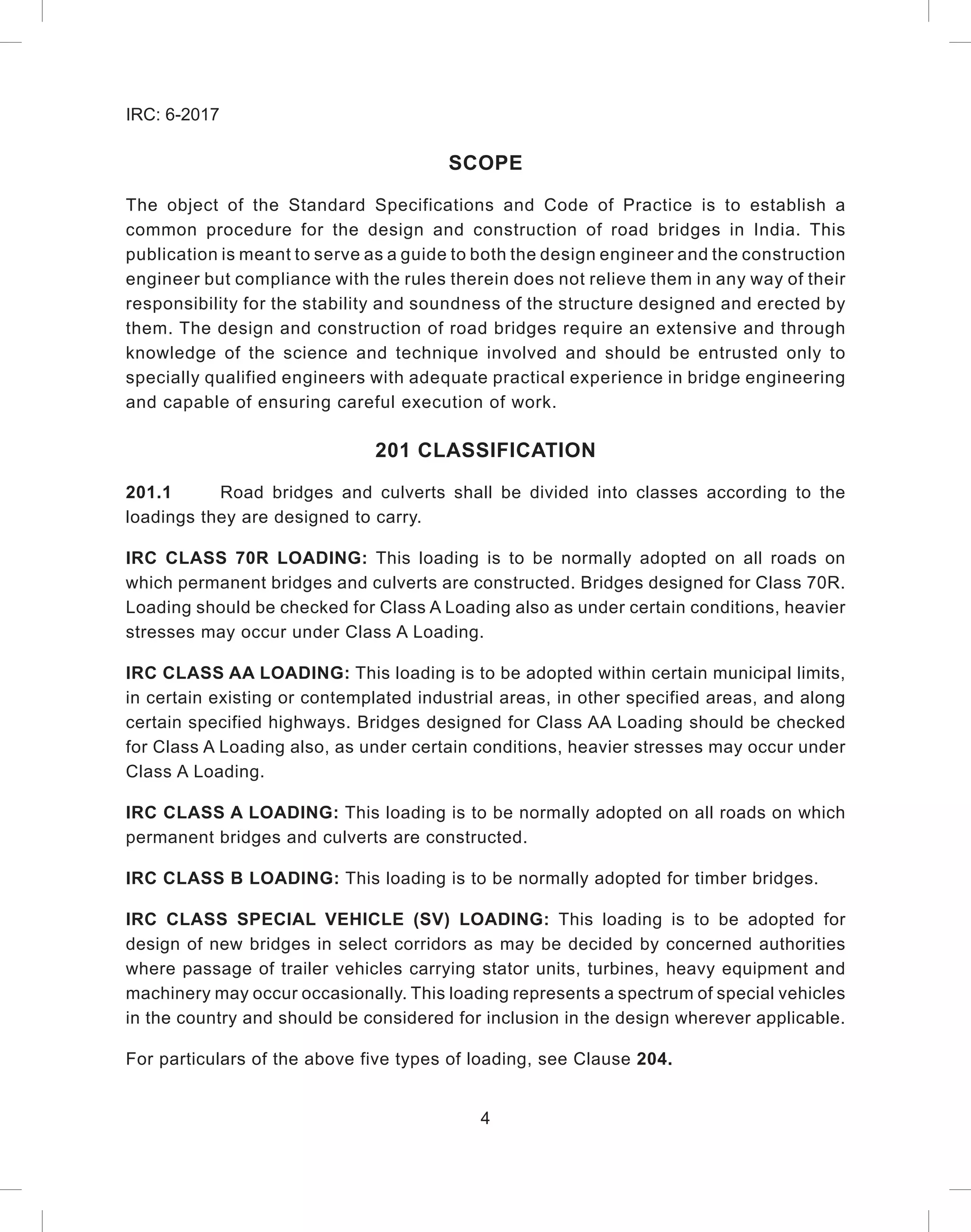
219.6 Barge Damage Depth, ‘aB
’
aB
= 3100 x ( [1 + 1.3 x 10(-7)
x KE]0.5
- 1),
where,
aB
= Barge blow damage depth (mm)
219.7 Barge Collision Impact Force, ‘PB
’
The barge collision impact force shall be determined based on the following equations:
For aB
100 mm, PB
= 6.0 x 10⁴
x (aB
), in N
For aB
≥ 100 mm, PB
= 6.0 x 10⁶
+ 1600 x (aB
), in N
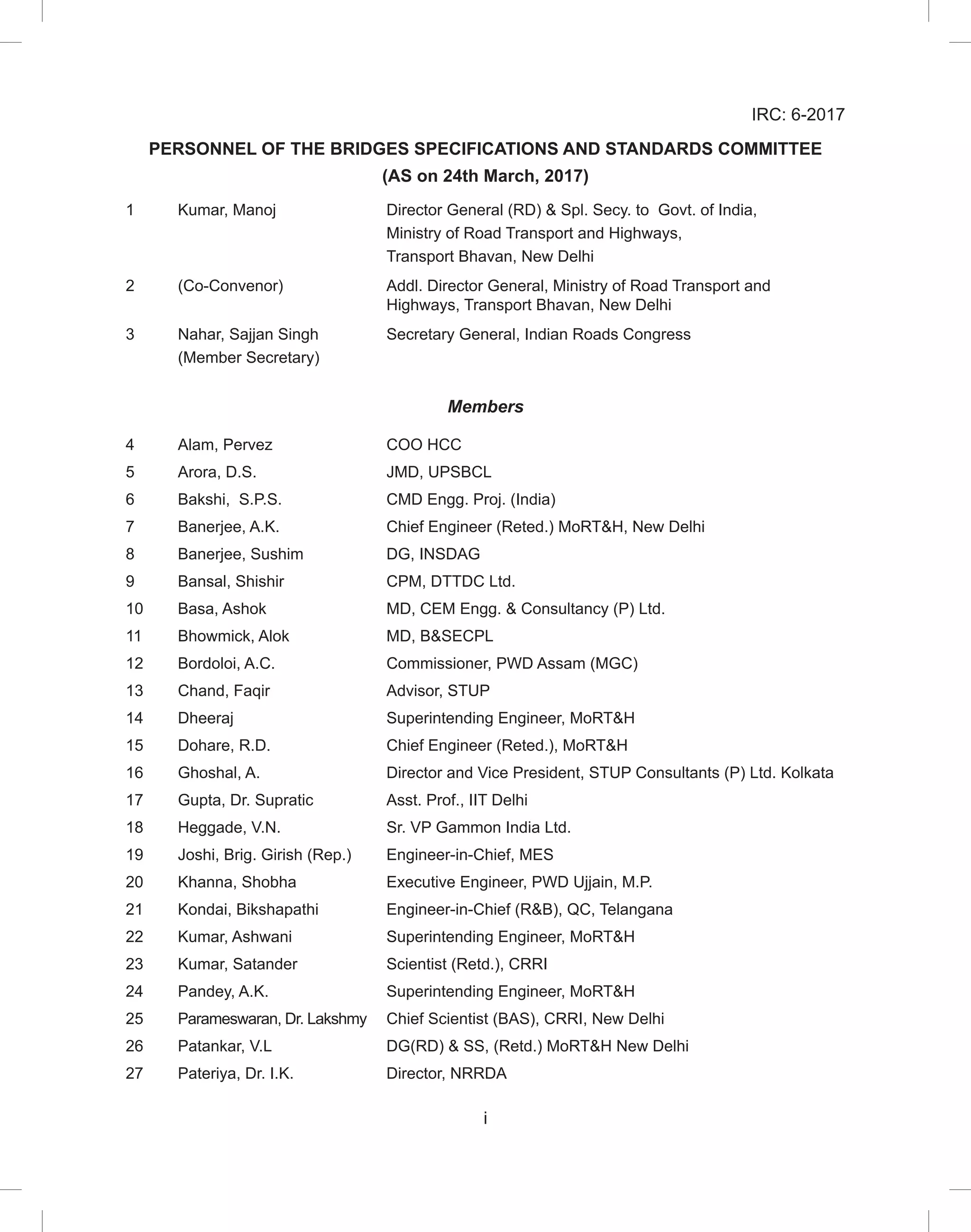
219.8 Location Magnitude of Impact Force in Substructure Foundation, ‘PB
’
All components of the substructure, exposed to physical contact by any portion of the
design barge’s hull or bow, shall be designed to resist the applied loads. The bow overhang,
rake, or flair distance of barges shall be considered in determining the portions of the
substructure exposed to contact by the barge. Crushing of the barge’s bow, causing
contact with any setback portion of the substructure shall also be considered.
Some of the salient barge dimensions to be checked while checking for the navigational
clearances are as follows.
The design impact force for the above cases is to be applied as a vertical line load
equally distributed along the barge’s bow depth, H2 defined with respect to the reference
water level as shown in Fig.25. The barge’s bow is considered to be raked forward in
determining the potential contact area of the impact force on the substructure.
219.9 Protection of Substructure
Protection may be provided to reduce or to eliminate the exposure of bridge substructures
to barge collision by physical protection systems, including fenders, pile cluster, pile-
supported structures, dolphins, islands, and combinations thereof.
Severe damage and/or collapse of the protection system may be permitted,
provided that the protection system stops the Barge prior to contact with the pier or
redirects the barge away from the pier. In such cases, the bridge piers need not be](https://image.slidesharecdn.com/irc-230429100357-30227d9f/75/irc-gov-in-006-2017-pdf-86-2048.jpg)


![84
IRC: 6-2017
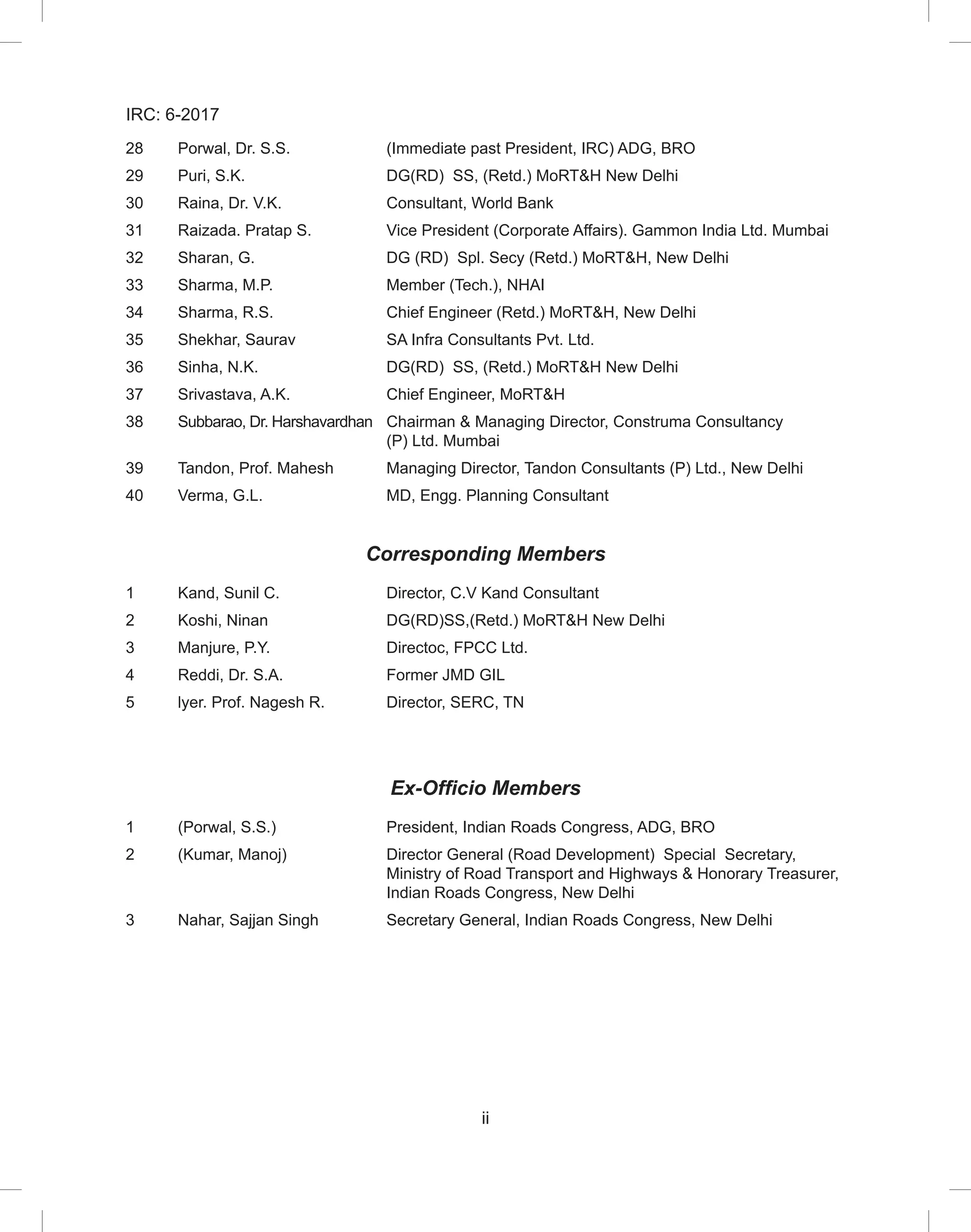
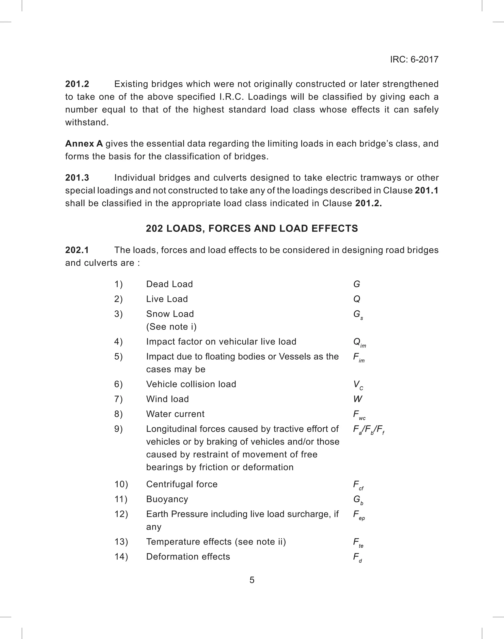
Annex A
(Clause 201.2)
HYPOTHETICAL VEHICLES FOR CLASSIFICATION OF VEHICLES
AND BRIDGES (REVISED)
NOTES FOR LOAD CLASSIFICATION CHART
1)
The possible variations in the wheel spacings and tyre sizes, for the heaviest single
axles-cols. (f) and (h), the heaviest bogie axles-col. (j) and also for the heaviest
axles of the train vehicle of cols. (e) and (g) are given in cols. (k), (I), (m) and (n).
The same pattern of wheel arrangement may be assumed for all axles of the wheel
train shown in cols. (e) and (g) as for the heaviest axles. The overall width of tyre in
mm may be taken as equal to [150+(p-1) 57], where “p” represents the load on tyre
in tonnes, wherever the tyre sizes are not specified on the chart.
2)
Contact areas of tyres on the deck may be obtained from the corresponding tyre
loads, max. tyre pressures (p) and width of tyre treads.
3)
The first dimension of tyre size refers to the overall width of tyre and second
dimension to the rim diameter of the tyre. Tyre tread width may be taken as overall
tyre width minus 25 mm for tyres upto 225 mm width, and minus 50 mm for tyres
over 225 mm width.
4)
The spacing between successive vehicles shall not be less than 30 m. This spacing
will be measured from the rear-most point of ground contact of the leading vehicles
to the forward-most point of ground contact of the following vehicle in case of tracked
vehicles. For wheeled vehicles, it will be measured from the centre of the rear-most
axle of the leading vehicle to the centre of the first axle of the following vehicle.
5)
The classification of the bridge shall be determined by the safe load carrying
capacity of the weakest of all the structural members including the main girders,
stringers (or load bearers), the decking, cross bearers (or transome) bearings, piers
and abutments, investigated under the track, wheel axle and bogie loads shown
for the various classes. Any bridge upto and including class 40 will be marked
with a single class number-the highest tracked or wheel standard load class which
the bridge can safely withstand. Any bridge over class 40 will be marked with a
single class number if the wheeled and tracked classes are the same, and with dual
classification sign showing both T and W load classes if the T and W classes are
different.](https://image.slidesharecdn.com/irc-230429100357-30227d9f/75/irc-gov-in-006-2017-pdf-91-2048.jpg)


![105
IRC: 6-2017
Himachal Pradesh Bhuntar (A) 40 -5.2
Dharamshala 42.7 -1.9
Kalpa (GL) 32.4 -15.5
Manali 35 -11.6
Nahan 43 -7.9
Nauni / Solan 39 -3.9
Shimla 32.4 -12.2
Sundernagar 42.1 -2.7
Una 45.2 -5.8
Jammu
and
Kashmir
Badarwah 39.4 -10.8
Banihal 36.3 -13.6
Batote 36.6 -7.2
Gulmarg 29.4 -19.8
Jammu 47.4 0.6
Kathua 48 -1.8
Katra 46.2 -1
Kukernag 34.9 -15.3
Kupwara 37.6 -15.7
Pehalgam 32.2 -18.6
Quazigund 35.7 -16.7
Srinagar 38..3 -20
Karnataka Agumbe 38 3.2
Bagalkote 42.8 7.8
Balehonnur 39.2 6.7
Bangaluru
[Bangalore]
38.9 7.8
Bangalore (A) 38.3 8.8
Belgaum 41.9 6.7
Belgaum (Sambre)
(A)
40.2 6.4
Bellary 44.7 7
Bidar 44 6.2
Bijapur 44.9 5.6
Chickmagalur 37 10
Chitradurga 41.7 8.3
Gadag 41.7 9.8
Gulbarga 46.1 5.6](https://image.slidesharecdn.com/irc-230429100357-30227d9f/75/irc-gov-in-006-2017-pdf-112-2048.jpg)


