Download as PDF, PPTX
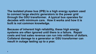


The isolated phase bus (IPB) connects large electric generators to the power grid. It operates reliably for decades with minimal care but failures can be costly. The presentation discusses common IPB designs and failure modes. Most failures can be prevented through proper inspection, maintenance, and testing. Key recommendations include keeping the IPB clean, dry, and performing routine visual inspections and infrared scans to detect deterioration early. Proper bolting techniques for connections are also emphasized as loose connections are a primary cause of failures.