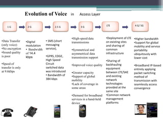
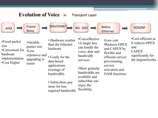
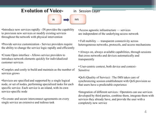
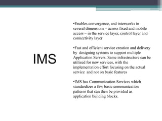
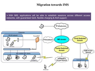
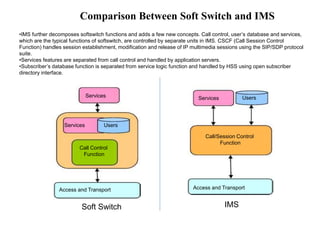
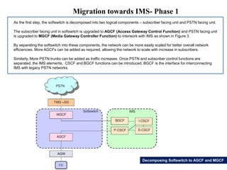
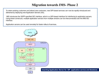
Telecom Study of IP 
Transformation 
By 
Altanai Bisht 
tara181989@gmail.com
1 G 2 G 2.5 G 3 G LTE 
• SMS (short 
messaging 
service), 
•GPRS, EDGE, 
High Speed 
Circuit 
switched data 
was introduced 
• Bandwidth of 
384 kbps 
•High-speed data 
transmissions 
•Symmetrical and 
asymmetrical data 
transmission support 
•Improved voice quality 
•Greater capacity 
•Support of global 
mobility 
•Lack of coverage in 
some areas 
•Demand for broadband 
services in a hand-held 
device 
•Deployment of LTE 
on existing sites 
and sharing of 
common 
infrastructure 
•Sharing of 
backhauling 
equipment 
between LTE/SAE 
and existing 
network 
technologies 
provided at the 
same site 
•Common network 
management 
platforms 
•Digital 
modulation 
• Bandwidth 
of 14.4 
kbps 
•Data Transfer 
(only voice) 
•No encryption 
•Sound quality 
is poor 
•Speed of 
transfer is only 
at 9.6kbps 
4 G/ 5G 
Evolution of Voice in Access Layer 
•Higher bandwidth 
•Support for global 
mobility and service 
portability 
ubiquitously with 
lower cost 
•Broadband IP-based 
entirely applying 
packet switching 
method of 
transmission with 
seamlessly access 
convergence
ATM 
Evolution of Voice in Transport Layer 
Frame 
Relay 
SDH/SONET NG- SDH Metro 
Ethernet 
ROADM 
• Hardware costlier 
than the Ethernet 
hardware 
• Costly for the 
data-based 
applications 
(wastage of 
bandwidth) 
• Subscribers pay 
more for less 
required bandwidth 
•Cost-effective 
•A single box 
can handle the 
voice, data and 
bandwidth 
services 
•More granular 
bandwidths are 
available and 
subscriber can 
enjoy the 
flexibility 
•Low cost 
•Reduces OPEX 
and CAPEX by 
flexible and 
efficient service 
provisioning, 
service 
activation and 
OAM functions 
•Cost-efficient as 
it reduces OPEX 
and 
CAPEX 
significantly for 
the largenetworks 
•Variable 
packet size 
•Less 
expensive and 
upgrading is 
easier 
•Fixed packet 
size 
•Convenient for 
hardware 
implementation 
•Cost Higher
4 
Evolution of Voice- in Session Layer 
IN IMS 
•Introduce new services rapidly - IN provides the capability 
to provision new services or modify existing services 
throughout the network with physical intervention 
•Provide service customization - Service providers require 
the ability to change the service logic rapidly and efficiently 
•Create Open interface - Allows service providers to 
introduce network elements quickly for individualized 
customer services 
•Complex and costly to build and maintain as the number of 
services grows 
•Services are specified and supported by a single logical 
node, or set of nodes, performing specialized tasks for each 
specific service. Each service is an island, with its own 
service-specific node 
•To create and secure interconnect agreements on every 
single service an extensive and tedious task 
•Access agnostic infrastructure — services 
are independent of the underlying access network 
• Full mobility — transparent connectivity across 
heterogeneous networks, protocols, and access mechanisms 
• Always on, always available capabilities, through sessions 
that cross networks and devices automatically and 
transparently 
• User-centric context, both device and context- 
Sensitive 
•QoS (Quality of Service) : The IMS takes care of 
synchronizing session establishment with QoS provision so 
that users have a predictable experience 
•Integration of different services : Operators can use services 
developed by third parties, combine them, integrate them with 
services they already have, and provide the user with a 
completely new service
•Enables convergence, and interworks in 
several dimensions – across fixed and mobile 
access – in the service layer, control layer and 
connectivity layer 
•Fast and efficient service creation and delivery 
by designing systems to support multiple 
Application Servers. Same infrastructure can be 
utilized for new services, with the 
implementation effort focusing on the actual 
service and not on basic features 
•IMS has Communication Services which 
standardizes a few basic communication 
patterns that can then be provided as 
application building blocks. 
IMS
Packet Cable Specification and DOCSIS
What is CMTS 
CMTS is a router with Ethernet interfaces (connections) on one side and coax RF 
interfaces on the other side. The RF/coax interfaces carry RF signals to and from the 
subscriber's cable modem. 
Architecture of a typical VoIP/SIP scenario
8
DOCSIS 
Data Over Cable Service Interface Specification (DOCSIS ) is an international 
telecommunications standard that permits the addition of high-speed data transfer to an 
existing cable TV(CATV) system. It is employed by many cable television operators to 
provide Internet access over their existing hybrid fiber-coaxial(HFC) infrastructure. 
Architecture of a typical VoIP/SIP scenario 
Features: 
Channel width: 
Down Steam- 6 MHz channels or 8 MHz channels 
upstream-between 200 kHz and 3.2 MHz DOCSIS 2.0 also specifies 6.4 MHz 
Modulation: 
Down Stream- 64-level or 256-level QAM 
Upstream- QPSK or 16-level QAM (16-QAM) for DOCSIS 1.x, and it uses QPSK, 8-QAM, 16-QAM, 32-QAM, 64-QAM 
for DOCSIS 2.0 & 3.0. DOCSIS 2.0 
 Throughput: 
Down Stream- 42.88 Mbits/s per 6 MHz channel, or 55.62 Mbit/s per 8 MHz channel 
Upstream- of 30.72 Mbit/s per 6.4 MHz channel, or 10.24 Mbit/s per 3.2 MHz channel
PacketCable 
 PacketCable architecture contains three networks: the "DOCSIS HFC Access Network", 
the "Managed IP Network" and the PSTN. The Cable Modem Termination System (CMTS) 
provides connectivity between the "DOCSIS HFC Access Network" and the "Managed IP 
Network". Both the Signaling Gateway (SG) and the Media Gateway (MG) provide 
connectivity between the "Managed IP Network" and the PSTN. 
Architecture of a typical VoIP/SIP scenario
PacketCable Implementation with Cisco BTS 
Architecture of a typical VoIP/SIP scenario
PacketCable Implementation- Contd.. 
 The diagram shows high level diagram of a PacketCable DQoS network architecture that shows the three segment 
model. In this diagram, the network elements impacted by DQoS are the Multimedia Terminal Adapter (MTA), the 
Cable Modem Termination System (CMTS), the Call Management Server (CMS), and the Record Keeping Server 
(RKS). 
 The Cisco BTS 10200 Softswitch performs the functions of the CMS in a DQoS capable network. 
Cable Modem Termination System (CMTS)-The CMTS is responsible for allocating and scheduling upstream and 
downstream bandwidth in accordance with MTA requests and QoS authorizations established by the network 
administrator. The CMTS implements a “DQoS Gate” between the DOCSIS cable network and an IP backbone. 
 Cable Modem (CM)-The CM is the PacketCable network element responsible for classifying, policing, and marking 
packets once the traffic flows are established by the DQoS signaling protocols. 
 Call Management Server (CMS)-The Call Management Server entity performs services that permit MTAs to 
establish Multimedia sessions . 
 Media Gateway Controller (MGC)-The Cisco BTS 10200 Softswitch performs the function of a media gateway 
controller (MGC),providing signaling to trunking gateways (TGWs). This allows calls to be connected between the 
PacketCable network and the PSTN
IMS Migration
Typical VOIP/SIP scenario without IMS 
Architecture of a typical VoIP/SIP scenario 
 A basic enterprise VoIP/SIP solution 
is illustrated in Figure. The key element 
is a soft switch (SIP PBX) which might 
be implemented as a combination of 
several SIP entities, such as SIP 
registrar, proxy server, redirect server, 
forking server, Back-To-Back User 
Agent (B2BUA) etc. 
 SIP clients can be SIP hard-phones 
or soft-phones on PCs, PDAs etc. A 
PSTN gateway links the enterprise SIP 
PBX to the public PSTN. 
 Enterprise applications, media 
servers, presence servers, and the 
VoIP/SIP PBX are interconnected 
through a company intranet.
Migration towards IMS 
 With IMS, applications will be able to establish sessions across different access 
networks, with guaranteed QoS, flexible charging & AAA support.
 In this solution, the enterprise domain always forks incoming calls to operator.com. 
The enterprises SIP PBX works as a forking proxy during call setup. 
INVITE 
Migration towards IMS- forking calls 
INVITE 
Forking Solution
Migration towards IMS- Roaming 
 When a user turns on a mobile terminal, it will register with the operator domain for 
access. World-wide access is supported thanks to operator-operator roaming agreements. 
Once able to send IP-packets, the client will contact the enterprise.com domain to register 
under its new location and thereby inform SIP PBX about the location change. 
INVITE 
INVITE 
Client Based Solution
Migration towards IMS- Presence 
In this solution, both domains interconnect their presence servers. These two domains 
have a business agreement so that they can watch the presence status off each other’s 
domain for certain clients. 
Presence Based Solution
Migration towards IMS- Possible Migration Scenarios 
This solution requires an initial setup as the operator needs to store information that a 
certain user belongs to a certain enterprise domain uses a certain pre-defined enterprise 
based SIP URI. 
 In enterprise domain there is an application server that handles the link registration using 
subscribe-notify mechanism to do link-register service subscription. 
Link Registration
Soft Switch Migration Towards IMS
Comparison Between Soft Switch and IMS 
•IMS further decomposes softswitch functions and adds a few new concepts. Call control, user’s database and services, 
which are the typical functions of softswitch, are controlled by separate units in IMS. CSCF (Call Session Control 
Function) handles session establishment, modification and release of IP multimedia sessions using the SIP/SDP protocol 
suite. 
•Services features are separated from call control and handled by application servers. 
•Subscriber’s database function is separated from service logic function and handled by HSS using open subscriber 
directory interface. 
Services Services 
Users 
Users 
Services 
Call Control 
Function 
Call/Session Control 
Function 
Access and Transport Access and Transport 
Soft Switch IMS
Migration towards IMS- Phase 1 
As the first step, the softswitch is decomposed into two logical components – subscriber facing unit and PSTN facing unit. 
The subscriber facing unit in softswitch is upgraded to AGCF (Access Gateway Control Function) and PSTN facing unit 
is upgraded to MGCF (Media Gateway Controller Function) to interwork with IMS as shown in Figure 3. 
By separating the softswitch into these components, the network can be more easily scaled for better overall network 
efficiencies. More AGCFs can be added as required, allowing the network to scale with increase in subscribers. 
Similarly, More PSTN trunks can be added as traffic increases. Once PSTN and subscriber control functions are 
separated, the IMS elements, CSCF and BGCF functions can be introduced. BGCF is the interface for interconnecting 
IMS with legacy PSTN networks. 
Decomposing Softswitch to AGCF and MGCF
Migration towards IMS- Phase 2 
To retain existing customers and attract new customers, new SIP-based services can now be rapidly introduced and 
delivered by deploying new Application Servers (AS). 
IMS introduces the 3GPP specified ISC interface, which is a SIP-based interface for interfacing to application servers. 
Using these constructs, multiple application servers from multiple vendors can be interconnected over the IMS ISC 
interface. 
Application servers can be used remotely for faster rollout of services. 
Inserting Application Server for SIP application service and Solutions
Migration towards IMS- Phase 3 
Moving toward fixed/mobile convergence(FMC), a service provider can address several business needs relating to the 
introduction of “triple play on the move.” 
The dual-mode devices can communicate over the cellular network, or act as a new endpoint on the IP network. 
The Home Subscriber Server (HSS), the last missing piece of the IMS architecture, is introduced. It is needed to manage 
subscriber data uniformly between the cellular and IP worlds. 
The Handoff Server is also introduced in this phase. It runs on top of the ISC interface, and provides a seamless 
experience when subscribers move from the cellular network to a Wi-Fi network. 
The AGCF remains the functional centre of the 
network, but with the introduction of the HSS, has 
added the Cx and Sh interfaces defined by the 
IMS, taking it a step further to becoming a 
complete SCSCF. 
Inserting HSS and Handoff Server for Fixed/Mobile Convergence
Thank you 
http://altanaitelecom.wordpress.com

Ip transformation by altanai

  • 1.
    Telecom Study ofIP Transformation By Altanai Bisht tara181989@gmail.com
  • 2.
    1 G 2G 2.5 G 3 G LTE • SMS (short messaging service), •GPRS, EDGE, High Speed Circuit switched data was introduced • Bandwidth of 384 kbps •High-speed data transmissions •Symmetrical and asymmetrical data transmission support •Improved voice quality •Greater capacity •Support of global mobility •Lack of coverage in some areas •Demand for broadband services in a hand-held device •Deployment of LTE on existing sites and sharing of common infrastructure •Sharing of backhauling equipment between LTE/SAE and existing network technologies provided at the same site •Common network management platforms •Digital modulation • Bandwidth of 14.4 kbps •Data Transfer (only voice) •No encryption •Sound quality is poor •Speed of transfer is only at 9.6kbps 4 G/ 5G Evolution of Voice in Access Layer •Higher bandwidth •Support for global mobility and service portability ubiquitously with lower cost •Broadband IP-based entirely applying packet switching method of transmission with seamlessly access convergence
  • 3.
    ATM Evolution ofVoice in Transport Layer Frame Relay SDH/SONET NG- SDH Metro Ethernet ROADM • Hardware costlier than the Ethernet hardware • Costly for the data-based applications (wastage of bandwidth) • Subscribers pay more for less required bandwidth •Cost-effective •A single box can handle the voice, data and bandwidth services •More granular bandwidths are available and subscriber can enjoy the flexibility •Low cost •Reduces OPEX and CAPEX by flexible and efficient service provisioning, service activation and OAM functions •Cost-efficient as it reduces OPEX and CAPEX significantly for the largenetworks •Variable packet size •Less expensive and upgrading is easier •Fixed packet size •Convenient for hardware implementation •Cost Higher
  • 4.
    4 Evolution ofVoice- in Session Layer IN IMS •Introduce new services rapidly - IN provides the capability to provision new services or modify existing services throughout the network with physical intervention •Provide service customization - Service providers require the ability to change the service logic rapidly and efficiently •Create Open interface - Allows service providers to introduce network elements quickly for individualized customer services •Complex and costly to build and maintain as the number of services grows •Services are specified and supported by a single logical node, or set of nodes, performing specialized tasks for each specific service. Each service is an island, with its own service-specific node •To create and secure interconnect agreements on every single service an extensive and tedious task •Access agnostic infrastructure — services are independent of the underlying access network • Full mobility — transparent connectivity across heterogeneous networks, protocols, and access mechanisms • Always on, always available capabilities, through sessions that cross networks and devices automatically and transparently • User-centric context, both device and context- Sensitive •QoS (Quality of Service) : The IMS takes care of synchronizing session establishment with QoS provision so that users have a predictable experience •Integration of different services : Operators can use services developed by third parties, combine them, integrate them with services they already have, and provide the user with a completely new service
  • 5.
    •Enables convergence, andinterworks in several dimensions – across fixed and mobile access – in the service layer, control layer and connectivity layer •Fast and efficient service creation and delivery by designing systems to support multiple Application Servers. Same infrastructure can be utilized for new services, with the implementation effort focusing on the actual service and not on basic features •IMS has Communication Services which standardizes a few basic communication patterns that can then be provided as application building blocks. IMS
  • 6.
  • 7.
    What is CMTS CMTS is a router with Ethernet interfaces (connections) on one side and coax RF interfaces on the other side. The RF/coax interfaces carry RF signals to and from the subscriber's cable modem. Architecture of a typical VoIP/SIP scenario
  • 8.
  • 9.
    DOCSIS Data OverCable Service Interface Specification (DOCSIS ) is an international telecommunications standard that permits the addition of high-speed data transfer to an existing cable TV(CATV) system. It is employed by many cable television operators to provide Internet access over their existing hybrid fiber-coaxial(HFC) infrastructure. Architecture of a typical VoIP/SIP scenario Features: Channel width: Down Steam- 6 MHz channels or 8 MHz channels upstream-between 200 kHz and 3.2 MHz DOCSIS 2.0 also specifies 6.4 MHz Modulation: Down Stream- 64-level or 256-level QAM Upstream- QPSK or 16-level QAM (16-QAM) for DOCSIS 1.x, and it uses QPSK, 8-QAM, 16-QAM, 32-QAM, 64-QAM for DOCSIS 2.0 & 3.0. DOCSIS 2.0  Throughput: Down Stream- 42.88 Mbits/s per 6 MHz channel, or 55.62 Mbit/s per 8 MHz channel Upstream- of 30.72 Mbit/s per 6.4 MHz channel, or 10.24 Mbit/s per 3.2 MHz channel
  • 10.
    PacketCable  PacketCablearchitecture contains three networks: the "DOCSIS HFC Access Network", the "Managed IP Network" and the PSTN. The Cable Modem Termination System (CMTS) provides connectivity between the "DOCSIS HFC Access Network" and the "Managed IP Network". Both the Signaling Gateway (SG) and the Media Gateway (MG) provide connectivity between the "Managed IP Network" and the PSTN. Architecture of a typical VoIP/SIP scenario
  • 11.
    PacketCable Implementation withCisco BTS Architecture of a typical VoIP/SIP scenario
  • 12.
    PacketCable Implementation- Contd..  The diagram shows high level diagram of a PacketCable DQoS network architecture that shows the three segment model. In this diagram, the network elements impacted by DQoS are the Multimedia Terminal Adapter (MTA), the Cable Modem Termination System (CMTS), the Call Management Server (CMS), and the Record Keeping Server (RKS).  The Cisco BTS 10200 Softswitch performs the functions of the CMS in a DQoS capable network. Cable Modem Termination System (CMTS)-The CMTS is responsible for allocating and scheduling upstream and downstream bandwidth in accordance with MTA requests and QoS authorizations established by the network administrator. The CMTS implements a “DQoS Gate” between the DOCSIS cable network and an IP backbone.  Cable Modem (CM)-The CM is the PacketCable network element responsible for classifying, policing, and marking packets once the traffic flows are established by the DQoS signaling protocols.  Call Management Server (CMS)-The Call Management Server entity performs services that permit MTAs to establish Multimedia sessions .  Media Gateway Controller (MGC)-The Cisco BTS 10200 Softswitch performs the function of a media gateway controller (MGC),providing signaling to trunking gateways (TGWs). This allows calls to be connected between the PacketCable network and the PSTN
  • 13.
  • 14.
    Typical VOIP/SIP scenariowithout IMS Architecture of a typical VoIP/SIP scenario  A basic enterprise VoIP/SIP solution is illustrated in Figure. The key element is a soft switch (SIP PBX) which might be implemented as a combination of several SIP entities, such as SIP registrar, proxy server, redirect server, forking server, Back-To-Back User Agent (B2BUA) etc.  SIP clients can be SIP hard-phones or soft-phones on PCs, PDAs etc. A PSTN gateway links the enterprise SIP PBX to the public PSTN.  Enterprise applications, media servers, presence servers, and the VoIP/SIP PBX are interconnected through a company intranet.
  • 15.
    Migration towards IMS  With IMS, applications will be able to establish sessions across different access networks, with guaranteed QoS, flexible charging & AAA support.
  • 16.
     In thissolution, the enterprise domain always forks incoming calls to operator.com. The enterprises SIP PBX works as a forking proxy during call setup. INVITE Migration towards IMS- forking calls INVITE Forking Solution
  • 17.
    Migration towards IMS-Roaming  When a user turns on a mobile terminal, it will register with the operator domain for access. World-wide access is supported thanks to operator-operator roaming agreements. Once able to send IP-packets, the client will contact the enterprise.com domain to register under its new location and thereby inform SIP PBX about the location change. INVITE INVITE Client Based Solution
  • 18.
    Migration towards IMS-Presence In this solution, both domains interconnect their presence servers. These two domains have a business agreement so that they can watch the presence status off each other’s domain for certain clients. Presence Based Solution
  • 19.
    Migration towards IMS-Possible Migration Scenarios This solution requires an initial setup as the operator needs to store information that a certain user belongs to a certain enterprise domain uses a certain pre-defined enterprise based SIP URI.  In enterprise domain there is an application server that handles the link registration using subscribe-notify mechanism to do link-register service subscription. Link Registration
  • 20.
  • 21.
    Comparison Between SoftSwitch and IMS •IMS further decomposes softswitch functions and adds a few new concepts. Call control, user’s database and services, which are the typical functions of softswitch, are controlled by separate units in IMS. CSCF (Call Session Control Function) handles session establishment, modification and release of IP multimedia sessions using the SIP/SDP protocol suite. •Services features are separated from call control and handled by application servers. •Subscriber’s database function is separated from service logic function and handled by HSS using open subscriber directory interface. Services Services Users Users Services Call Control Function Call/Session Control Function Access and Transport Access and Transport Soft Switch IMS
  • 22.
    Migration towards IMS-Phase 1 As the first step, the softswitch is decomposed into two logical components – subscriber facing unit and PSTN facing unit. The subscriber facing unit in softswitch is upgraded to AGCF (Access Gateway Control Function) and PSTN facing unit is upgraded to MGCF (Media Gateway Controller Function) to interwork with IMS as shown in Figure 3. By separating the softswitch into these components, the network can be more easily scaled for better overall network efficiencies. More AGCFs can be added as required, allowing the network to scale with increase in subscribers. Similarly, More PSTN trunks can be added as traffic increases. Once PSTN and subscriber control functions are separated, the IMS elements, CSCF and BGCF functions can be introduced. BGCF is the interface for interconnecting IMS with legacy PSTN networks. Decomposing Softswitch to AGCF and MGCF
  • 23.
    Migration towards IMS-Phase 2 To retain existing customers and attract new customers, new SIP-based services can now be rapidly introduced and delivered by deploying new Application Servers (AS). IMS introduces the 3GPP specified ISC interface, which is a SIP-based interface for interfacing to application servers. Using these constructs, multiple application servers from multiple vendors can be interconnected over the IMS ISC interface. Application servers can be used remotely for faster rollout of services. Inserting Application Server for SIP application service and Solutions
  • 24.
    Migration towards IMS-Phase 3 Moving toward fixed/mobile convergence(FMC), a service provider can address several business needs relating to the introduction of “triple play on the move.” The dual-mode devices can communicate over the cellular network, or act as a new endpoint on the IP network. The Home Subscriber Server (HSS), the last missing piece of the IMS architecture, is introduced. It is needed to manage subscriber data uniformly between the cellular and IP worlds. The Handoff Server is also introduced in this phase. It runs on top of the ISC interface, and provides a seamless experience when subscribers move from the cellular network to a Wi-Fi network. The AGCF remains the functional centre of the network, but with the introduction of the HSS, has added the Cx and Sh interfaces defined by the IMS, taking it a step further to becoming a complete SCSCF. Inserting HSS and Handoff Server for Fixed/Mobile Convergence
  • 25.