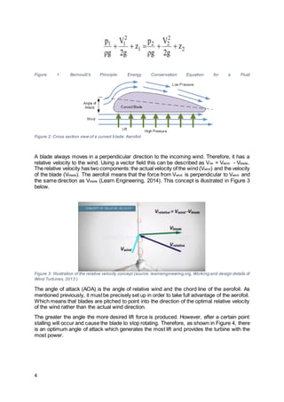
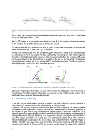
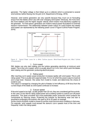
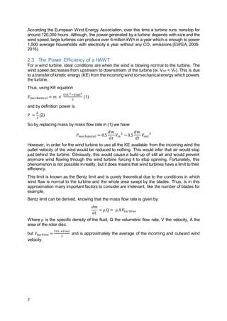
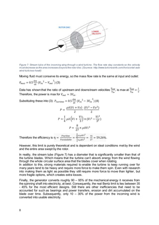
This document provides an overview of wind turbines and their mechanical properties. It discusses how wind turbines work by capturing the kinetic energy of wind and converting it to electrical energy. The key components that enable this are the turbine blades, which are designed with an aerodynamic shape called an aerofoil that generates lift from the wind. The optimal angle of attack for the blades is important to maximize energy capture while avoiding stall. Wind turbines start generating power at a minimum wind speed and reach maximum power output at their rated wind speed before feathering their blades at very high wind speeds to protect components. The theoretical maximum efficiency of a wind turbine is calculated as 1/3 of the incoming wind speed based on fluid dynamics principles.

![14
*The Renewables Obligation (RO) is one of the main support mechanisms for large-scale
renewable electricity projects in the UK. […] The RO came into effect in 2002 in England and
Wales, and Scotland, followed by Northern Ireland in 2005. It places an obligation on UK
electricity suppliers to source an increasing proportion of the electricity they supply from
renewable sources.’ (Office of Gas and Electricity Markets, 2016)
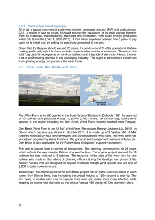
** based on the wind farm’s predicted energy yield of 37.55GWh and the 2013 UK average
annual household energy consumption to be 4128kWh from data published by the Department
of Energy and Climate Change.
3 Discussion
One of the main reproaches faced by wind turbines today is their lack of power efficiency. At
30% efficiency at best, they are well behind other current leading energy sources, particularly
those powered from fossil fuels. However, ways of increasing their overall power output are
becoming more and moreattainable. In particular, blades in new models are looking to exceed
100m in length. Lots of research is focussing on finding a new kind of material with the best
combination of high strength to low weight ratio material for blades, as well as, long lasting
materials and coatings to produce prolong the device’s lifespan. While staying reasonably
priced.
3.1 How to enhance wind turbine designs?
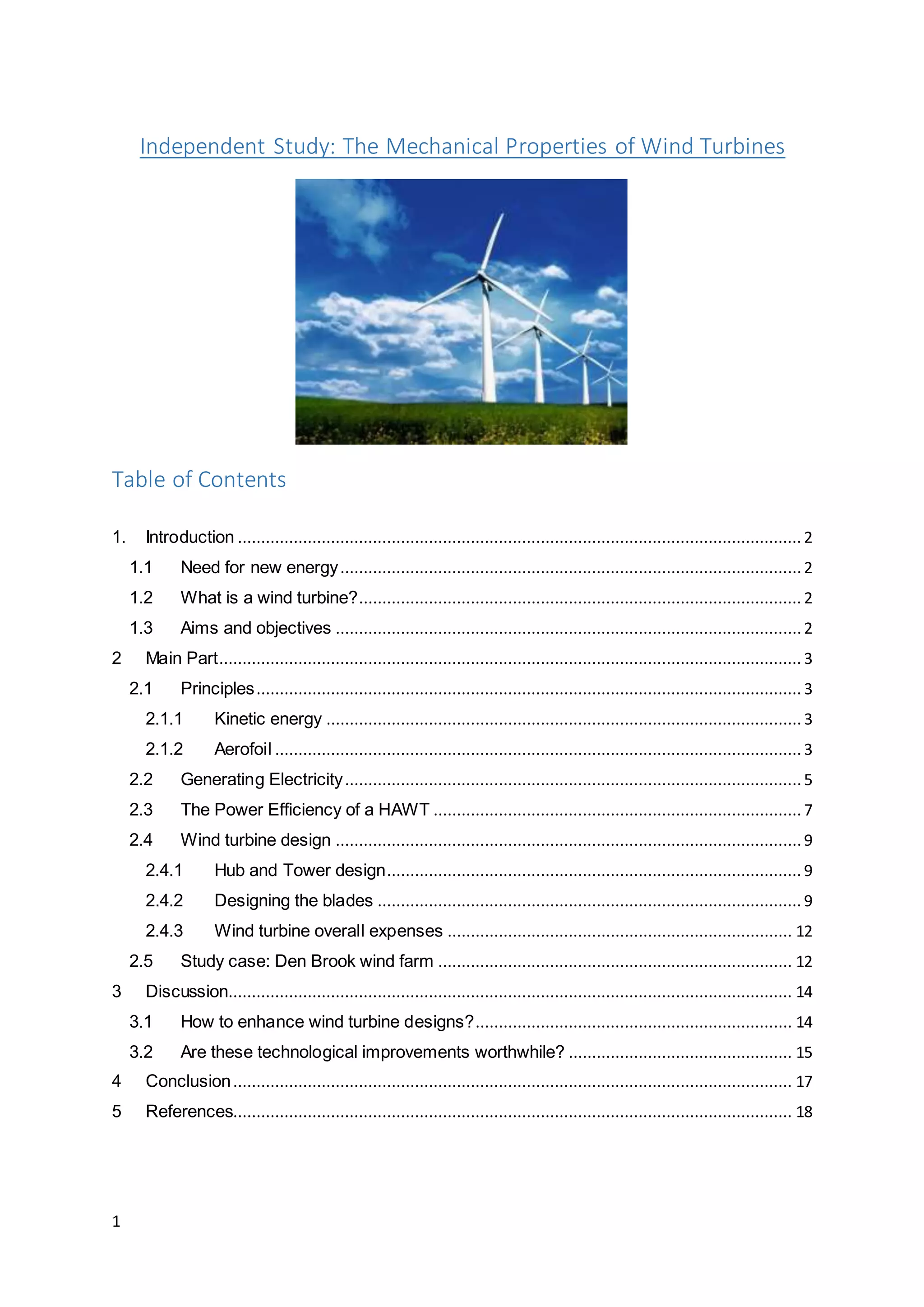
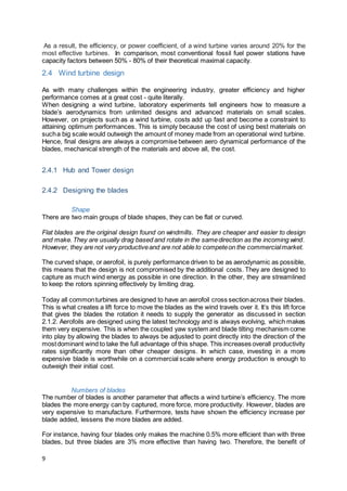
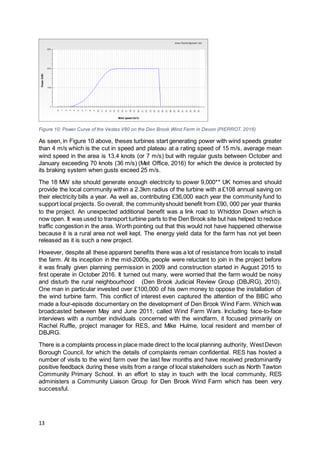
Some are already experimenting with carbon fibre blades, because they are somewhat
stronger than fibre-glass and much less dense could solve this issue. Unluckily, it a lot more
expensive to buy and to handle when manufacturing. These statements are made obvious
from Figure 11, that compares the density, strength and cost of different fibres used to build
wind turbine blades
Yet, another important point to account for is that by having lighter blades the tower and the
rest of the turbine components do not have to be as strong and stiff to cope with any excess
weight. Therefore, in somecases,the extra costof investing carbon fibre could be outweighed
by the additional power that can be produced by the extra length in the blades, as well as, by
cutting the costs of the materials for the rest of the turbine.
Figure 11: ACP Composites fibre matrix comparison ( ACP Composites, 2010)](https://image.slidesharecdn.com/0439cc26-c459-4ce9-863e-3c4dfc5e06a0-170124184400/85/IP-attempt-2-14-320.jpg)
![18
5 References
ACPComposites,2010. Acpsales.com. [Online]
Available at:http://www.acpsales.com/pages.php?pageid=35
[Accessed2016 10 24].
Conserve-Energy-Futur,2016. [Online]
Available at:http://www.conserve-energy-future.com/AlternativeEnergySources.php
Conti-Ramsden,D.J.,2015. http://www.renewableenergyworld.com. [Online]
Available at:http://www.renewableenergyworld.com/articles/2015/07/materials-are-blowing-in-
the-wind.html
[Accessed2016 10 25].
Daniels,L.,2005. Windustry. [Online]
Available at:http://www.windustry.org/community_wind_toolbox_5_siting_guidelines
[Accessed111 2016].
DenBrook Judicial ReviewGroup(DBJRG),2010. Denbrookvalley.co.uk. [Online]
Available at:http://www.denbrookvalley.co.uk/files/PressRelease_20July10.pdf
[Accessed112 2016].
DWEA, 2014. [Online]
Available at:http://distributedwind.org/wp-content/uploads/2012/08/DWEA-Tower-Height.pdf
[Accessed11 11 2016].
Ethan Zindler,2015. Bloomberg NewEnergy Finance. [Online]
Available at:https://about.bnef.com/press-releases/wind-solar-boost-cost-competitiveness-versus-
fossil-fuels/
[Accessed18 11 2016].
EWEA, 2005-2016. Wind energy frequently asked questions(FAQ)|EWEA. [Online]
Available at:http://www.ewea.org/wind-energy-basics/faq/
[Accessed310 2016].
Gardner BusinessMedia,2016. Wind turbineblades:Glass vs.carbon fiber: CompositesWorld.
[Online]
Available at:http://www.compositesworld.com/articles/wind-turbine-blades-glass-vs-carbon-fiber
[Accessed23 10 2016].
InternetbureauRedkiwi,2011 -2016. EWT B.V.. [Online]
Available at:http://www.ewtdirectwind.com/technology/direct-drive-technology.html
[Accessed512 2016].
Komal Habib,,.H. W.,20 January2016. Reviewingresource criticalityassessmentfromadynamic
and technologyspecificperspective –usingthe case of direct-drive windturbines.In: Jornalof
Cleanerproduction. s.l.:Elsevier,p.3852–3863.
Learn Engineering,2014. Howdo Wind Turbineswork?. [Online]
Available at:https://www.youtube.com/watch?v=qSWm_nprfqE
[Accessed510 2016].
Ltd, L. S. L. -.A. E. C. a. V.,2016. [Interview] (1011 2016).](https://image.slidesharecdn.com/0439cc26-c459-4ce9-863e-3c4dfc5e06a0-170124184400/85/IP-attempt-2-18-320.jpg)
![19
Met Office,2016. metoffice.gov.uk. [Online]
Available at:http://www.metoffice.gov.uk/public/weather/climate/gbvrpf1yf
[Accessed512 2016].
MIT WindEnergyGroup &RenewableEnergyProjectsinActionRenewable EnergyProjectsinAction,
n.d. Wind PowerFundamentals. s.l.:s.n.
National ResearchCouncil,1991. Assessmentof Research NeedsforWind TurbineRotor Materials
Technology. [Online]
Available at:https://www.nap.edu/read/1824/chapter/5#39
[Accessed811 2016].
Nixon,N.,2008. Timeline: The history of wind power. [Online]
Available at:https://www.theguardian.com/environment/2008/oct/17/wind-power-renewable-
energy
[Accessed112 2016].
Office of Gas and ElectricityMarkets,2016. Office of Gas and Electricity Markets. [Online]
Available at:https://www.ofgem.gov.uk/environmental-programmes/ro/about-ro
[Accessed512 2016].
PIERROT,M., 2016. The Wind Power. [Online]
Available at:http://www.thewindpower.net/turbine_en_30_vestas_2000.php
[Accessed112 2016].
Pilotsweb.com, 2005. Pilotsweb.com. [Online]
Available at:http://www.pilotsweb.com/principle/liftdrag.htm
[Accessed30 10 2016].
RenewableEnergySystemsLtd,2016. Den BrookWind Farm. [Online]
Available at:http://www.den-brook.co.uk/
[Accessed112 2016].
Sanne Wittrup,2014. BIOFOS. [Online]
Available at:https://ing.dk/artikel/lm-windpower-bygger-verdens-laengste-vindmoellevinge-185073
[Accessed512 2016].
U.S. Departmentof Energy,2016. Energy.gov. [Online]
Available at:http://www.energy.gov/eere/wind/inside-wind-turbine-0
[Accessed210 2016].
WindPowerProgram,2016. Wind-power-program.com. [Online]
Available at:http://www.wind-power-program.com/turbine_characteristics.htm
[Accessed811 2016].](https://image.slidesharecdn.com/0439cc26-c459-4ce9-863e-3c4dfc5e06a0-170124184400/85/IP-attempt-2-19-320.jpg)