Download to read offline
![IJRET: International Journal of Research in Engineering and Technology eISSN: 2319-1163 | pISSN: 2321-7308
__________________________________________________________________________________________
Volume: 03 Special Issue: 07 | May-2014, Available @ http://www.ijret.org 129
INVALIDATING VULNERABLE BROADCASTER NODES USING
MAXIMUM LIKELIHOOD EXPECTATION
Jeril Kuriakose1
, Amruth V2
, Swathy Nandhini N3
, Iyer Snehal Gopalakrishnan4
, Cyril Kuriakose5
1
Research Scholar, School of Computing and Information Technology (SCIT), Manipal University Jaipur, Jaipur, India
2
Assistant Professor, Department of Information Science and Engineering, Bearys Institute of Technology, Mangalore,
India
3
Assistant Professor, Department of Information Technology, Jayam College of Engineering and Technology,
Dharmapuri, India
4
M Tech student, SCIT, Manipal University Jaipur, Jaipur, India
5
Senior Support Executive, Allsec Technology Ltd., Chennai, India
Abstract
Discovering the cheating or vulnerable anchor node (or broadcaster node) is an essential problem in wireless sensor networks
(WSNs). In wireless sensor networks, anchor nodes are the nodes that know its current location. Neighboring nodes or non-anchor
nodes calculate its location (or its location reference) with the help of anchor nodes. Ingenuous localization is not possible in the
presence of a cheating anchor node or a cheating node. Nowadays, it’s a challenging task to identify the cheating anchor node or
cheating node in a network. Even after finding out the location of the cheating anchor node, there is no assurance, that the identified
node is legitimate or not. This paper aims to localize the cheating anchor nodes using trilateration algorithm and later associate it
with maximum likelihood expectation technique (MLE) to obtain maximum accuracy in localization. We were able to attain a
considerable reduction in the error achieved during localization. For implementation purpose we simulated our scheme using ns-3
network simulator.
Keywords: Maximum likelihood expectation; trilateration; anchor node; security; distance-based localization; wireless
sensor networks;
-----------------------------------------------------------------------***----------------------------------------------------------------------
1. INTRODUCTION
Wireless ad hoc and sensor networks are on a steady rise in
the recent decade. This is because of their reduced cost in
deployment and maintenance. Advancements in radio
frequency spectrum also carved way for the improvement in
the data rate for communication. Many devices belong to
wireless ad hoc and sensor networks; one among them is
anchor node [1 - 8]. Anchor nodes are the nodes that know its
current location. Neighboring nodes or non-anchor nodes
calculate its location (or location reference) with the help of
anchor nodes, and its working is quite referable to Light
House.
The location of the nodes plays a significant role in many
areas as routing, surveillance and monitoring, military etc. The
sensor nodes must know their location reference to carryout
Location-based routing (LR) [9 - 12]. To find out the shortest
route, the Location Aided Routing (LAR) [13 - 15] makes use
of the locality reference of the sensor nodes. In some
industries the sensor nodes are used to identify minute changes
as pressure, temperature and gas leak, and in military, robots
are used to detect landmines where in both the cases location
information plays a key part.
Anchor nodes can also be used to find the current location of
any device (mobile phones, objects and people). It does that
by transmitting anchor frames periodically or at regular
intervals. Usually anchor frames are used to advertise the
occurrence of a wireless modem or an Access Point (AP).
Each anchor frame carries some details about the
configuration of AP and a little security information for the
clients.
When the technologies are on a massive upswing, the need for
security of the relevant technologies arises. There can be
several occasion where the anchor nodes can be vulnerable to
security breach. Because of the security breach the anchor
node starts to cheat by giving false information. In the
presence of cheating anchor nodes the chances of localization
drastically decreases. Many papers [16 - 19] discuss about the
localization of cheating anchor nodes, but with inconsistent
accuracy. So, to overcome this, we localize the cheating or
vulnerable anchor node using trilateration technique and](https://image.slidesharecdn.com/invalidatingvulnerablebroadcasternodesusing-140824234343-phpapp01/85/Invalidating-vulnerable-broadcaster-nodes-using-1-320.jpg)
![IJRET: International Journal of Research in Engineering and Technology eISSN: 2319-1163 | pISSN: 2321-7308
__________________________________________________________________________________________
Volume: 03 Special Issue: 07 | May-2014, Available @ http://www.ijret.org 130
associate the results with maximum likelihood expectation
technique [20].
Organization of the paper - Section 2 provides the
localization using trilateration algorithm and section 3 studies
the maximum likelihood expectation. Simulation and results
are covered in section 4 and section 5 concludes the paper.
2. LOCALIZATION USING TRILATERATION
ALGORITHM
Anchor nodes are widely used for tacking and localization;
whereas nowadays it is also used for navigation and route-
identification. With the help of anchor nodes, a user can find
out his current location. Consider a scenario like a hotel or
museum, there may be many occasions where people go out of
track. Thiscan be flabbergasted by installing anchor nodes
installed in various locations, so that people can trace out there
location very easily and it ispossible only when the anchor
nodes are authentic. Nowadays hackers are on a rise; anybody
can easily get into any system and change its settings.
Similarly, they can hack any anchor nodes and change its
location reference to some other false location reference,
making people lose their track; thus leading to a bad imprint
about the system (i.e., hotel, museum).
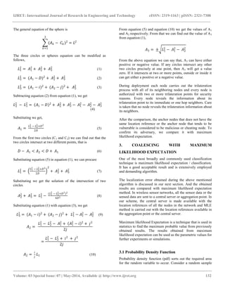
An attack is exemplified in fig. 1 and fig. 2. Fig. 1 shows the
initial deployment of anchor nodes A1, A2, A3; with location
reference (x1, y1), (x2, y2), (x3, y3); and distance L1, L2, L3;
respectively, from the trilateration point T, having location
reference (xt, yt). Fig. 2 demonstrates the logical deployment
of anchor nodes after the attack i.e., multiple changes in
location reference of anchor node A2.
The three dimensional location coordinate of any device or
node can be estimated using trilateration calculations.
Trilateration technique uses distance measurements rather than
angular measurements; latter technique is also used in many
localization techniques [21 -23, 32]. Using some iterative
schemes like least square, least median square [17], least
trimmed square [24] and gradient descent [25], can equitably
increase the accuracy of trilateration technique.
Fig. 1. Initial setup of anchor nodes
Fig. 2. Anchor nodes after attack
Trilateration techniques use the distance measurement
between the nodes to calculate the location reference. The
distances between the nodes are identified using Received
Signal Strength (RSSI) [26, 32] or Time of Arrival (ToA) [27,
28, 32] or Time Difference of Arrival (TDoA) [29, 30, 32].
When a node (requesting node) wants to identify its location
information using trilateration technique, it does with the help
of three or more neighboring anchor nodes. The
exemplification of trilateration techniques is as follows:
a) A node that wants to find its location reference (or
location coordinate) sends a localization request to any](https://image.slidesharecdn.com/invalidatingvulnerablebroadcasternodesusing-140824234343-phpapp01/85/Invalidating-vulnerable-broadcaster-nodes-using-2-320.jpg)
![IJRET: International Journal of Research in Engineering and Technology eISSN: 2319-1163 | pISSN: 2321-7308
__________________________________________________________________________________________
Volume: 03 Special Issue: 07 | May-2014, Available @ http://www.ijret.org 131
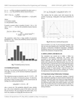
of its neighboring anchor nodes. The anchor node sends
a reply with its current location reference and its RSSI
measurement with respect to the node that wants to
localize. Based on this information, we put up a virtual
wireless ring (VWR) (or logical ring) [31] as shown in
fig. 3. The assumption of the logical ring is made with
the anchor node as center. The requesting node can be
located anywhere on the circumference of the logical
ring, and thus making it difficult to guess its exact
location.
Fig. 3. Virtual wireless ring with one anchor node
b) Next the same requesting node sends another
localization request to a different neighboring anchor
node. The anchor node follows the same process as
discussed in the previous step. Again another logical
ring is updated to the previous one, shown in fig. 4.
From the logical observation we can analyze that the
location of the requesting node could be present in any
one of the intersecting point of the two logical rings.
Fig. 4. Virtual wireless ring with two anchor nodes
c) Finally to ease the muddle, the same requesting node
sends another localization request to a different
neighboring anchor node other than the previous two
anchor nodes. The same process is repeated with the
new neighboring anchor node. When the final virtual
wireless ring is drawn, we would be able to extract the
exact location of the requesting node. Fig. 5 shows the
localization of a node using trilateration technique.
Fig. 5. Virtual wireless ring with three anchor node
The mathematical computation of trilateration is as follows:
Consider three circles or spheres with center C1, C2 and C3,
radius L1, L2 and L3 from points A1, A2 and A3 (anchor node
location), refer fig. 6.
Fig.6. Trilateration measurements](https://image.slidesharecdn.com/invalidatingvulnerablebroadcasternodesusing-140824234343-phpapp01/85/Invalidating-vulnerable-broadcaster-nodes-using-3-320.jpg)

![IJRET: International Journal of Research in Engineering and Technology eISSN: 2319-1163 | pISSN: 2321-7308
__________________________________________________________________________________________
Volume: 03 Special Issue: 07 | May-2014, Available @ http://www.ijret.org 135
using Maximum Likelihood Expectation we can obtain
consistent and efficient results. Our results show that as the
malicious anchor nodes increases, the simulation time and
error obtained during location discovery slightly increases.
The accuracy obtained in our work can be used as assistance
in some wireless applications.
REFERENCES
[1] R. Want, A. Hopper, V. Falcao, and J. Gibbons, “The
Active Badge Location System,” ACM Trans.
Information Systems, vol. 10, pp. 91 - 102, 1992.
[2] J. Liu, Y. Zhang, and F. Zhao, “Robust Distributed
Node Localization with Error Management,”
Proceedings ACM MobiHoc, 2006
[3] M.W. Carter, H.H. Jin, M.A. Saunders, and Y. Ye,
“SpaseLoc: An Adaptive Subproblem Algorithm for
Scalable Wireless Sensor Network Localization,” SIAM
J. Optimization, 2006.
[4] P. Bahl and V.N. Padmanabhan, “RADAR: An In-
Building RFBased User Location and Tracking
System,” Proc. IEEE INFOCOM, 2000.
[5] D. Niculescu and B. Nath, “DV Based Positioning in
Ad Hoc Networks,” J. Telecomm. Systems, vol. 22, pp.
267-280, 2003.
[6] N. Priyantha, A. Chakraborty, and H. Balakrishnan,
“The Cricket Location-Support System,” Proc. ACM
MobiCom, 2000.
[7] R. Stoleru and J.A. Stankovic, “Probability Grid: A
Location Estimation Scheme for Wireless Sensor
Networks,” Proc. First IEEE Conf. Sensor and Ad Hoc
Comm. and Networks (SECON ’04), 2004.
[8] N. Bulusu, J. Heidemann, and D. Estrin, “GPS-Less
Low Cost Outdoor Localization for Very Small
Devices,” IEEE Personal Comm. Magazine, vol. 7, no.
5, pp. 28-34, Oct. 2000.
[9] Tracy Camp, Jeff Boleng, Brad Williams, Lucas
Wilcox and William Navidi, “Performance Comparison
of Two Location Based Routing Protocols for Ad Hoc
Networks,” IEEE Infocom, 2002.
[10] LjubicaBlazevic, Jean-Yves Le Boudec and Silvia
Giordano, “A Location-Based Routing Method for
Mobile Ad Hoc Networks,” IEEE Transactions on
Mobile Computing, 2005.
[11] HolgerFußler, Martin Mauve, et al., “Location Based
Routing for Vehicular AdHoc Networks,” Proceedings
of ACM MOBICOM, 2002.
[12] H. Qu, S. B. Wicke, “Co-designed anchor-free
localization and location-based routing algorithm for
rapidly-deployed wireless sensor networks,”
Information Fusion, 2008.
[13] F. Kuhn, R. Wattenhofer, A. Zollinger, “Worst-case
optimal and average-case efficient geometric ad-hoc
routing,” Proceedings of the 4th ACM International
Symposium on Mobile Ad Hoc Networking &
Computing, 2003.
[14] Karim El Defrawy, Gene Tsudik, “ALARM:
Anonymous Location-Aided Routing in Suspicious
MANETs,”
[15] Young-BaeKo and Nitin H. Vaidya, “Location-Aided
Routing (LAR) in mobile ad hoc networks,” Wireless
Networks, 2000
[16] MurtuzaJadliwala, Sheng Zhong, ShambhuUpadhyaya,
ChunmingQiao and Jean-Pierre Hubaux, “Secure
Distance-Based Localization in the Presence of
Cheating Anchor Nodes,” IEEE Transactions on
Mobile Computing, 2010.
[17] Z. Li, W. Trappe, Y. Zhang, and B. Nath, “Robust
Statistical Methods for Securing Wireless Localization
in Sensor Networks,” Proceedings of Fourth
International Symposium on Information Processing in
Sensor Networks (IPSN ’05), 2005.
[18] D. Liu, P. Ning, and W. Du, “Attack-Resistant
Location Estimation in Sensor Networks,” Proceedings
of Fourth International Symposium on Information
Processing in Sensor Networks (IPSN ’05), 2005.
[19] D. Liu, P. Ning, and W. Du, “Detecting Malicious
Beacon Nodes for Secure Location Discovery in
Wireless Sensor Networks,” Proceedings of 25th
International Conference Distributed Computing
Systems (ICDCS ’05), 2005.
[20] In Jae Myung, “Tutorial on maximum likelihood
estimation,” Journal of Mathematical Psychology,
2003.
[21] R. Peng, M. L. Sichitiu, “Angle of Arrival Localization
for Wireless Sensor Networks,” Third Annual IEEE
Communications Society Conference on Sensor and Ad
Hoc Communications and Networks, 2006.
[22] D. Niculescu and B. Nath, “Ad hoc positioning system
(APS) using AOA,” IEEE INFOCOM, 2003.
[23] A. Nasipuri and K. Li, “A directionality based location
discovery scheme for wireless sensor networks,” ACM
International Workshop on Wireless Sensor Networks
and Applications, 2002.
[24] P. Rousseeuw and K. Driessen, “Computing LTS
regression for large data sets,” Data Mining Knowledge
Discovery, vol. 12, no. 1, pp. 29–45, 2006.
[25] Ravi Garg, Avinash L. Varna and Min Wu, “An
Efficient Gradient Descent Approach to Secure
Localization in Resource Constrained Wireless Sensor
Networks,” IEEE Transactions on Information
Forensics and Security, Vol. 7, No. 2, April 2012.
[26] G. Mao, B.D.O. Anderson, and B. Fidan, “Path Loss
Exponent Estimation for Wireless Sensor Network
Localization,” Computer Networks, vol. 51, pp. 2467-
2483, 2007.
[27] R. Moses, D. Krishnamurthy, and R. Patterson, “A
Self-Localization Method for Wireless Sensor
Networks,” Eurasip J. Applied Signal Processing,
special issue on sensor networks, vol. 2003, pp. 348-
358, 2003.](https://image.slidesharecdn.com/invalidatingvulnerablebroadcasternodesusing-140824234343-phpapp01/85/Invalidating-vulnerable-broadcaster-nodes-using-7-320.jpg)
![IJRET: International Journal of Research in Engineering and Technology eISSN: 2319-1163 | pISSN: 2321-7308
__________________________________________________________________________________________
Volume: 03 Special Issue: 07 | May-2014, Available @ http://www.ijret.org 136
[28] G. Sarigiannidis, “Localization for Ad Hoc Wireless
Sensor Networks,” M.S. thesis, Technical University
Delft, The Netherlands, August 2006.
[29] J. Xiao, L. Ren, and J. Tan, “Research of TDOA Based
Self-Localization Approach in Wireless Sensor
Network,” Proceedings IEEE/RSJ International
Conference on Intelligent Robots and Systems, 2006.
[30] N. Priyantha, A. Chakraborty, and H. Balakrishnan,
“The Cricket Location-Support System,” Proceedings
ACM MobiCom, 2000.
[31] George Aggelou, Mobile Ad Hoc Networks from
Wireless LANs to 4G Network, India: Tata McGraw
Hill Education, 2009, Print.
[32] Jeril Kuriakose, Sandeep Joshi, VikramRaju R, and
AravindKilaru, "A Review on Localization in Wireless
Sensor Networks," Advances in Signal Processing and
Intelligent Recognition Systems. Springer International
Publishing, 2014. 599-610.
[33] http://en.wikipedia.org/wiki/3-sphere
[34] http://en.wikipedia.org/wiki/Trilateration
BIOGRAPHIES
Jeril Kuriakose received the B Tech degree
from Jeppiaar Engineering College, India,
in 2010, and M Tech degree from
University of Mysore, India, in 2012, all in
information technology. He is currently
pursuing PhD in Manipal University Jaipur,
India. His research interests include mobile computing, mobile
ad hoc network, network and information security, and
scientific computing
Amruth V received B Tech Degree from
Coorg Institute of Technology, India, and M
Tech Degree from University of Mysore,
India, in 2009 and 2012, respectively, all in
information technology. At present he is
working as assistant professor in Bearys
Institute of Technology, Mangalore, India, in the department
of information science and engineering. His research areas
include remote sensing, algorithms, network and information
security, and wireless networking.
Swathy Nandhini N completed UG degree
in KSR College of Engineering and PG
degree in VaruvanVadivelan Institute of
Technology, Anna University, in India, in
2010 and 2012, respectively.At present she
is working as assistant professor in Jayam
College of Engineering and Technology. Herarea of interest
includes Cryptography and Network Security, Computer
Networks, Operating Systems, and Web Technology.
Iyer Snehal Gopalakrishnan is a M
Tech student in Manipal University
Jaipur, India. He completed his B Tech
in Computer Science from Coorg
Institute of Technology, in India, in
2012. His research interests include
mobile ad hoc network, number theory and crytography, and
wireless sensor network.
Cyril Kuriakose is a senior support
executive at Allsec Technologies Ltd.
He received the B.Sc. degree from St.
Joseph‟s College, Trichy, India, in 2007,
and M.Sc. degree from Kongu
Engineering College, India, in 2012, in
computer science and information technology, respectively.
He is a Governor and President Award winner in scout, in
2001 and 2002, respectively. His research areas include
wireless sensor network, ad hoc network, cryptography, and
network security.](https://image.slidesharecdn.com/invalidatingvulnerablebroadcasternodesusing-140824234343-phpapp01/85/Invalidating-vulnerable-broadcaster-nodes-using-8-320.jpg)

This document describes a method for identifying vulnerable or cheating anchor nodes in a wireless sensor network using trilateration and maximum likelihood expectation. Trilateration is used to localize anchor nodes based on distance measurements, which can identify potential cheating nodes. The localized nodes are then analyzed using maximum likelihood expectation to determine the most probable nodes and validate if identified nodes are legitimate or cheating with high accuracy. The method was tested through simulation in ns-3, and was able to significantly reduce localization errors compared to other techniques.


![[IJET-V1I3P14] Authors :Kruthika R.](https://cdn.slidesharecdn.com/ss_thumbnails/ijet-v1i3p14-150618182420-lva1-app6891-thumbnail.jpg?width=640&height=640&fit=bounds)