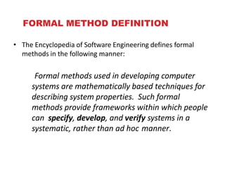
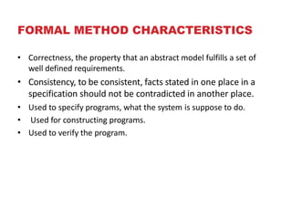
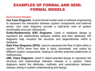
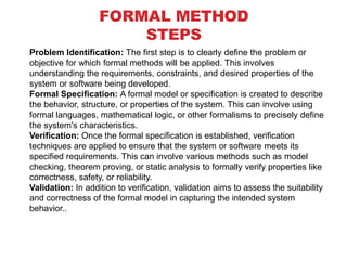
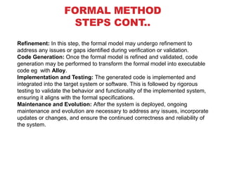
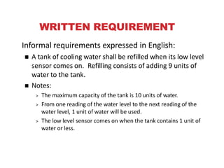
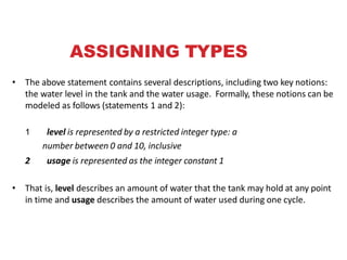
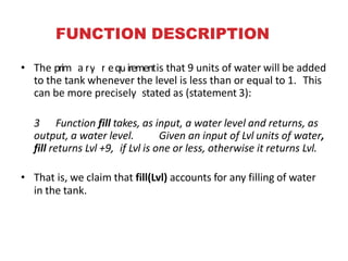
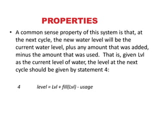
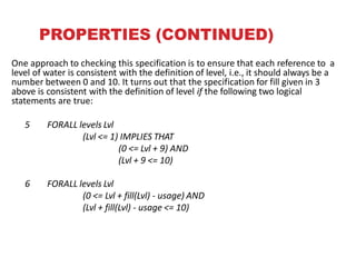
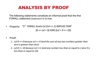
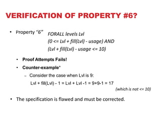
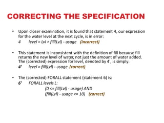
FORMAL METHODS IN SOFTWARE
ENGINEERING
NDZE REGINA KUKIWIN
Uba20S0900
FS, Math and C.S
CSCS5102 – Software Engineering 2
FORMAL METHOD DEFINITION
• The Encyclopedia of Software Engineering defines formal
methods in the following manner:
Formal methods used in developing computer
systems are mathematically based techniques for
describing system properties. Such formal
methods provide frameworks within which people
can specify, develop, and verify systems in a
systematic, rather than ad hoc manner.
FORMAL METHOD CHARACTERISTICS
• Correctness, the property that an abstract model fulfills a set of
well defined requirements.
• Consistency, to be consistent, facts stated in one place in a
specification should not be contradicted in another place.
• Used to specify programs, what the system is suppose to do.
• Used for constructing programs.
• Used to verify the program.
WHY FORMAL METHODS ARE REQUIRED
⚫History of software
⚫Softwares encountered notorious bugs that were the
cause of financial lose and deaths of many people.
⚫Famous bugs are
⚫Therac-25
⚫ Computerized radiation therapy machine called the Therac-25. Killed
many people, controller could not stop radiation due to software bug.
⚫AT & T long distance breakdown bug 1990
⚫ Ill placed break statement in the code, caused the 1/3rd of entire
American network to go down for 9 hours.
WHY FORMAL METHODS ARE REQUIRED
– Patriot Missile Failure Gulf war
• This missile hit the own American troops a software
defect in 1991. Killing 28 people and many injured
– Pentium bug
• Software error in microcode of Pentium
microprocessor, which resulted in error of floating point
calculation problems. Intel had to take back all the
Pentiums, and it caused huge loss.
IMPORTANCE OF FORMAL METHODS IN
SOFTWARE
⚫This is what we are going to study in formal methods.
⚫Methods to ensure that software is
⚫ Correct
⚫Reliable
⚫These two attributes deal with the software quality.
⚫To achieve software quality, we apply different
techniques.
⚫Testing
⚫Verification
⚫Validation
TESTING
• Black box testing
– Test input versus output
– Input
• Two numbers
– Output
• average
• White box testing
– Test the structure of program.
• Loops testing, condition testing
"TESTING CAN SHOW THE PRESENCE OF ERRORS,
BUT NOT THEIR ABSENCE."
- Edsger Dijkstra
TESTING
CONTD..
• In testing we develop test cases and define
scenarios, it is not possible to have all
scenarios .
• Program to show equalness of two strings.
• isEqual(“cat”,”dog”) expected false
• isEqual(“testing”,”testing”) expected true
• isEqual(“house”,”home”) expected false
• isEqual(“house”,”mouse”) expected false.
HOW FORMAL METHODS ARE
DEVELOPED?
• We develop models of system.
• With the help of models we will argue and
prove correctness of models.
• What is a model?
– An item, a structure, a style,….
EXAMPLES OF FORMAL AND SEMI-
FORMAL MODELS
Formal Models:
State Machines: A formal model that represents the
behavior of a system through a set of states and transitions
between them. State machines can be represented using
formal languages like Finite State Machines (FSM) or Petri
Nets.
Mathematical Logic: Formal models using mathematical
logic, such as propositional logic, predicate logic, or
temporal logic, to specify properties, constraints, and
relationships within a system.
EXAMPLES OF FORMAL AND SEMI-
FORMAL MODELS
Semi-Formal Models:
Use Case Diagrams: A semi-formal model used in software engineering
to represent the interaction between system components and external
actors. Use case diagrams provide a high-level view of system
functionality and user interactions.
Entity-Relationship (ER) Diagrams: Used in database design to
represent the relationships between entities and their attributes. ER
diagrams help visualize the structure and dependencies within a
database.
Data Flow Diagrams (DFD): Used to represent the flow of data within a
system. DFDs show how data is input, processed, and output by
different system components, helping to identify potential bottlenecks or
inefficiencies.
UML Class Diagrams: Used in object-oriented design to represent the
structure and relationships between classes in a system. Class
diagrams depict the attributes, methods, and associations between
classes, aiding in system understanding and design.
FORMAL METHOD
STEPS
Problem Identification: The first step is to clearly define the problem or
objective for which formal methods will be applied. This involves
understanding the requirements, constraints, and desired properties of the
system or software being developed.
Formal Specification: A formal model or specification is created to describe
the behavior, structure, or properties of the system. This can involve using
formal languages, mathematical logic, or other formalisms to precisely define
the system's characteristics.
Verification: Once the formal specification is established, verification
techniques are applied to ensure that the system or software meets its
specified requirements. This can involve various methods such as model
checking, theorem proving, or static analysis to formally verify properties like
correctness, safety, or reliability.
Validation: In addition to verification, validation aims to assess the suitability
and correctness of the formal model in capturing the intended system
behavior..
FORMAL METHOD
STEPS CONT..
Refinement: In this step, the formal model may undergo refinement to
address any issues or gaps identified during verification or validation.
Code Generation: Once the formal model is refined and validated, code
generation may be performed to transform the formal model into executable
code eg with Alloy.
Implementation and Testing: The generated code is implemented and
integrated into the target system or software. This is followed by rigorous
testing to validate the behavior and functionality of the implemented system,
ensuring it aligns with the formal specifications.
Maintenance and Evolution: After the system is deployed, ongoing
maintenance and evolution are necessary to address any issues, incorporate
updates or changes, and ensure the continued correctness and reliability of
the system.
WRITTEN REQUIREMENT
Informal requirements expressed in English:
 A tank of cooling water shall be refilled when its low level
sensor comes on. Refilling consists of adding 9 units of
water to the tank.
 Notes:
> The maximum capacity of the tank is 10 units of water.
> From one reading of the water level to the next reading of the
water level, 1 unit of water will be used.
> The low level sensor comes on when the tank contains 1 unit of
water or less.
e F
ASSIGNING TYPES
• The above statement contains several descriptions, including two key notions:
the water level in the tank and the water usage. Formally, these notions can be
modeled as follows (statements 1 and 2):
1 level is represented by a restricted integer type: a
number between 0 and 10, inclusive
2 usage is represented as the integer constant 1
• That is, level describes an amount of water that the tank may hold at any point
in time and usage describes the amount of water used during one cycle.
FUNCTION DESCRIPTION
• The primMaertyhordesquxirementis that 9 units of water will be added
to the tank whenever the level is less than or equal to 1. This
can be more precisely stated as (statement 3):
3 Function fill takes, as input, a water level and returns, as
output, a water level. Given an input of Lvl units of water,
fill returns Lvl +9, if Lvl is one or less, otherwise it returns Lvl.
• That is, we claim that fill(Lvl) accounts for any filling of water
in the tank.
PROPERTIES
• A common sense property of this system is that, at
the next cycle, the new water level will be the
current water level, plus any amount that was added,
minus the amount that was used. That is, given Lvl
as the current level of water, the level at the next
cycle should be given by statement 4:
4 level = Lvl + fill(Lvl) - usage
e
PROPERTIES (CONTINUED)
One approach to checking this specification is to ensure that each reference to a
level of water is consistent with the definition of level, i.e., it should always be a
number between 0 and 10. It turns out that the specification for fill given in 3
above is consistent with the definition of level if the following two logical
statements are true:
5 FORALL levels Lvl
(Lvl <= 1) IMPLIES THAT
(0 <= Lvl + 9) AND
(Lvl + 9 <= 10)
6 FORALL levels Lvl
(0 <= Lvl + fill(Lvl) - usage) AND
(Lvl + fill(Lvl) - usage <= 10)
ANALYSIS BY PROOF
• Property: “5” FORALL levels Lvl (Lvl <= 1) IMPLIES THAT
(0 <= Lvl + 9) AND (Lvl + 9 <= 10)
• Proof:
1. Lvl+9 >= 0 because Lvl >= 0 (and the sum of any two numbers greater than
zero is greater than zero)
2. Lvl+9 <= 10 because Lvl <=1 (and any number less than or equal to 1 plus 9 is
less than or equal to 10)
The following statements constitute an informal proof that the first
FORALL statement (statement 5) is true
VERIFICATION OF PROPERTY #6?
• Proof Attempts Fails!
• Counter-example*
– Consider the case when Lvl is 9:
Lvl + fill(Lvl) - 1 = Lvl + Lvl -1 = 9+9-1 = 17
• Property “6” FORALL levels Lvl
(0 <= Lvl + fill(Lvl) - usage) AND
(Lvl + fill(Lvl) - usage <= 10)
(which is not <= 10)
• The specification is flawed and must be corrected.
e Formal Me ample
CORRECTING THE SPECIFICATION
• Upon closer examination, it is found that statement 4, our expression
for the water level at the next cycle, is in error:
4 level = Lvl + fill(Lvl) - usage (incorrect)
• This statement is inconsistent with the definition of fill because fill
returns the new level of water, not just the amount of water added.
The (corrected) expression for level, denoted by 4', is simply:
4' level = fill(Lvl) - usage (correct)
• The (corrected) FORALL statement (statement 6) is:
6' FORALL levels L:
(0 <= fill(Lvl) - usage) AND
(fill(Lvl) - usage <= 10) (correct)

Introduction to formal methods lecture notes

  • 1.
    FORMAL METHODS INSOFTWARE ENGINEERING NDZE REGINA KUKIWIN Uba20S0900 FS, Math and C.S CSCS5102 – Software Engineering 2
  • 2.
    FORMAL METHOD DEFINITION •The Encyclopedia of Software Engineering defines formal methods in the following manner: Formal methods used in developing computer systems are mathematically based techniques for describing system properties. Such formal methods provide frameworks within which people can specify, develop, and verify systems in a systematic, rather than ad hoc manner.
  • 3.
    FORMAL METHOD CHARACTERISTICS •Correctness, the property that an abstract model fulfills a set of well defined requirements. • Consistency, to be consistent, facts stated in one place in a specification should not be contradicted in another place. • Used to specify programs, what the system is suppose to do. • Used for constructing programs. • Used to verify the program.
  • 4.
    WHY FORMAL METHODSARE REQUIRED ⚫History of software ⚫Softwares encountered notorious bugs that were the cause of financial lose and deaths of many people. ⚫Famous bugs are ⚫Therac-25 ⚫ Computerized radiation therapy machine called the Therac-25. Killed many people, controller could not stop radiation due to software bug. ⚫AT & T long distance breakdown bug 1990 ⚫ Ill placed break statement in the code, caused the 1/3rd of entire American network to go down for 9 hours.
  • 5.
    WHY FORMAL METHODSARE REQUIRED – Patriot Missile Failure Gulf war • This missile hit the own American troops a software defect in 1991. Killing 28 people and many injured – Pentium bug • Software error in microcode of Pentium microprocessor, which resulted in error of floating point calculation problems. Intel had to take back all the Pentiums, and it caused huge loss.
  • 6.
    IMPORTANCE OF FORMALMETHODS IN SOFTWARE ⚫This is what we are going to study in formal methods. ⚫Methods to ensure that software is ⚫ Correct ⚫Reliable ⚫These two attributes deal with the software quality. ⚫To achieve software quality, we apply different techniques. ⚫Testing ⚫Verification ⚫Validation
  • 7.
    TESTING • Black boxtesting – Test input versus output – Input • Two numbers – Output • average • White box testing – Test the structure of program. • Loops testing, condition testing
  • 8.
    "TESTING CAN SHOWTHE PRESENCE OF ERRORS, BUT NOT THEIR ABSENCE." - Edsger Dijkstra
  • 9.
    TESTING CONTD.. • In testingwe develop test cases and define scenarios, it is not possible to have all scenarios . • Program to show equalness of two strings. • isEqual(“cat”,”dog”) expected false • isEqual(“testing”,”testing”) expected true • isEqual(“house”,”home”) expected false • isEqual(“house”,”mouse”) expected false.
  • 10.
    HOW FORMAL METHODSARE DEVELOPED? • We develop models of system. • With the help of models we will argue and prove correctness of models. • What is a model? – An item, a structure, a style,….
  • 11.
    EXAMPLES OF FORMALAND SEMI- FORMAL MODELS Formal Models: State Machines: A formal model that represents the behavior of a system through a set of states and transitions between them. State machines can be represented using formal languages like Finite State Machines (FSM) or Petri Nets. Mathematical Logic: Formal models using mathematical logic, such as propositional logic, predicate logic, or temporal logic, to specify properties, constraints, and relationships within a system.
  • 12.
    EXAMPLES OF FORMALAND SEMI- FORMAL MODELS Semi-Formal Models: Use Case Diagrams: A semi-formal model used in software engineering to represent the interaction between system components and external actors. Use case diagrams provide a high-level view of system functionality and user interactions. Entity-Relationship (ER) Diagrams: Used in database design to represent the relationships between entities and their attributes. ER diagrams help visualize the structure and dependencies within a database. Data Flow Diagrams (DFD): Used to represent the flow of data within a system. DFDs show how data is input, processed, and output by different system components, helping to identify potential bottlenecks or inefficiencies. UML Class Diagrams: Used in object-oriented design to represent the structure and relationships between classes in a system. Class diagrams depict the attributes, methods, and associations between classes, aiding in system understanding and design.
  • 13.
    FORMAL METHOD STEPS Problem Identification:The first step is to clearly define the problem or objective for which formal methods will be applied. This involves understanding the requirements, constraints, and desired properties of the system or software being developed. Formal Specification: A formal model or specification is created to describe the behavior, structure, or properties of the system. This can involve using formal languages, mathematical logic, or other formalisms to precisely define the system's characteristics. Verification: Once the formal specification is established, verification techniques are applied to ensure that the system or software meets its specified requirements. This can involve various methods such as model checking, theorem proving, or static analysis to formally verify properties like correctness, safety, or reliability. Validation: In addition to verification, validation aims to assess the suitability and correctness of the formal model in capturing the intended system behavior..
  • 14.
    FORMAL METHOD STEPS CONT.. Refinement:In this step, the formal model may undergo refinement to address any issues or gaps identified during verification or validation. Code Generation: Once the formal model is refined and validated, code generation may be performed to transform the formal model into executable code eg with Alloy. Implementation and Testing: The generated code is implemented and integrated into the target system or software. This is followed by rigorous testing to validate the behavior and functionality of the implemented system, ensuring it aligns with the formal specifications. Maintenance and Evolution: After the system is deployed, ongoing maintenance and evolution are necessary to address any issues, incorporate updates or changes, and ensure the continued correctness and reliability of the system.
  • 15.
    WRITTEN REQUIREMENT Informal requirementsexpressed in English:  A tank of cooling water shall be refilled when its low level sensor comes on. Refilling consists of adding 9 units of water to the tank.  Notes: > The maximum capacity of the tank is 10 units of water. > From one reading of the water level to the next reading of the water level, 1 unit of water will be used. > The low level sensor comes on when the tank contains 1 unit of water or less. e F
  • 16.
    ASSIGNING TYPES • Theabove statement contains several descriptions, including two key notions: the water level in the tank and the water usage. Formally, these notions can be modeled as follows (statements 1 and 2): 1 level is represented by a restricted integer type: a number between 0 and 10, inclusive 2 usage is represented as the integer constant 1 • That is, level describes an amount of water that the tank may hold at any point in time and usage describes the amount of water used during one cycle.
  • 17.
    FUNCTION DESCRIPTION • TheprimMaertyhordesquxirementis that 9 units of water will be added to the tank whenever the level is less than or equal to 1. This can be more precisely stated as (statement 3): 3 Function fill takes, as input, a water level and returns, as output, a water level. Given an input of Lvl units of water, fill returns Lvl +9, if Lvl is one or less, otherwise it returns Lvl. • That is, we claim that fill(Lvl) accounts for any filling of water in the tank.
  • 18.
    PROPERTIES • A commonsense property of this system is that, at the next cycle, the new water level will be the current water level, plus any amount that was added, minus the amount that was used. That is, given Lvl as the current level of water, the level at the next cycle should be given by statement 4: 4 level = Lvl + fill(Lvl) - usage e
  • 19.
    PROPERTIES (CONTINUED) One approachto checking this specification is to ensure that each reference to a level of water is consistent with the definition of level, i.e., it should always be a number between 0 and 10. It turns out that the specification for fill given in 3 above is consistent with the definition of level if the following two logical statements are true: 5 FORALL levels Lvl (Lvl <= 1) IMPLIES THAT (0 <= Lvl + 9) AND (Lvl + 9 <= 10) 6 FORALL levels Lvl (0 <= Lvl + fill(Lvl) - usage) AND (Lvl + fill(Lvl) - usage <= 10)
  • 20.
    ANALYSIS BY PROOF •Property: “5” FORALL levels Lvl (Lvl <= 1) IMPLIES THAT (0 <= Lvl + 9) AND (Lvl + 9 <= 10) • Proof: 1. Lvl+9 >= 0 because Lvl >= 0 (and the sum of any two numbers greater than zero is greater than zero) 2. Lvl+9 <= 10 because Lvl <=1 (and any number less than or equal to 1 plus 9 is less than or equal to 10) The following statements constitute an informal proof that the first FORALL statement (statement 5) is true
  • 21.
    VERIFICATION OF PROPERTY#6? • Proof Attempts Fails! • Counter-example* – Consider the case when Lvl is 9: Lvl + fill(Lvl) - 1 = Lvl + Lvl -1 = 9+9-1 = 17 • Property “6” FORALL levels Lvl (0 <= Lvl + fill(Lvl) - usage) AND (Lvl + fill(Lvl) - usage <= 10) (which is not <= 10) • The specification is flawed and must be corrected. e Formal Me ample
  • 22.
    CORRECTING THE SPECIFICATION •Upon closer examination, it is found that statement 4, our expression for the water level at the next cycle, is in error: 4 level = Lvl + fill(Lvl) - usage (incorrect) • This statement is inconsistent with the definition of fill because fill returns the new level of water, not just the amount of water added. The (corrected) expression for level, denoted by 4', is simply: 4' level = fill(Lvl) - usage (correct) • The (corrected) FORALL statement (statement 6) is: 6' FORALL levels L: (0 <= fill(Lvl) - usage) AND (fill(Lvl) - usage <= 10) (correct)