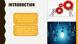
The document discusses various advanced control systems used in process control and instrumentation, including on-off controllers, feed-forward control, feedback control, ratio control, adaptive controllers, and cascade control. Each system is explained in terms of its operation, advantages, disadvantages, and common applications, emphasizing their roles in maintaining desired performance in industrial processes. It provides insight into the mechanics of how these controllers adjust outputs based on input variables, aiming for optimal control and efficiency.


![INTRODUCTION
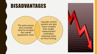
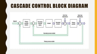
The simplest cascade control scheme involves two control loops that use two
measurement signals to control one primary variable.
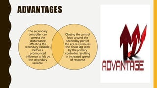
In such a control system, the output of the primary controller determines the set point
for the secondary controller.
The output of the secondary controller is used to adjust the control variable.
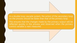
Generally, the secondary controller changes quickly while the primary controller
changes slowly.
Once cascade control is implemented, disturbances from rapid changes of the
secondary controller will not affect the primary controller. [ Extracted from : Wikipedia ]](https://image.slidesharecdn.com/advancedcontrolsystem-240721075231-4e59a043/85/introduction-to-advanced-control-systems-55-320.jpg)

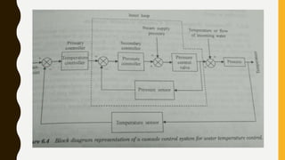
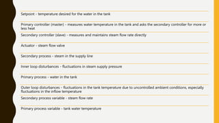
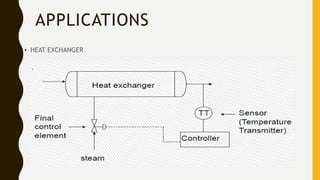
![In the water heater example, the tank temperature controller would be primary since it defines
the setpoint that the steam flow controller is required to achieve. The water in the tank, the
tank temperature, the steam, and the steam flow rate would be the primary process, the
primary process variable, the secondary process, and the secondary process variable,
respectively (refer to the Cascade Control Block Diagram). The valve that the steam flow
controller uses to maintain the steam flow rate serves as the actuator which acts directly on
the secondary process and indirectly on the primary process.[ Extracted from : controleng.com
]](https://image.slidesharecdn.com/advancedcontrolsystem-240721075231-4e59a043/85/introduction-to-advanced-control-systems-60-320.jpg)