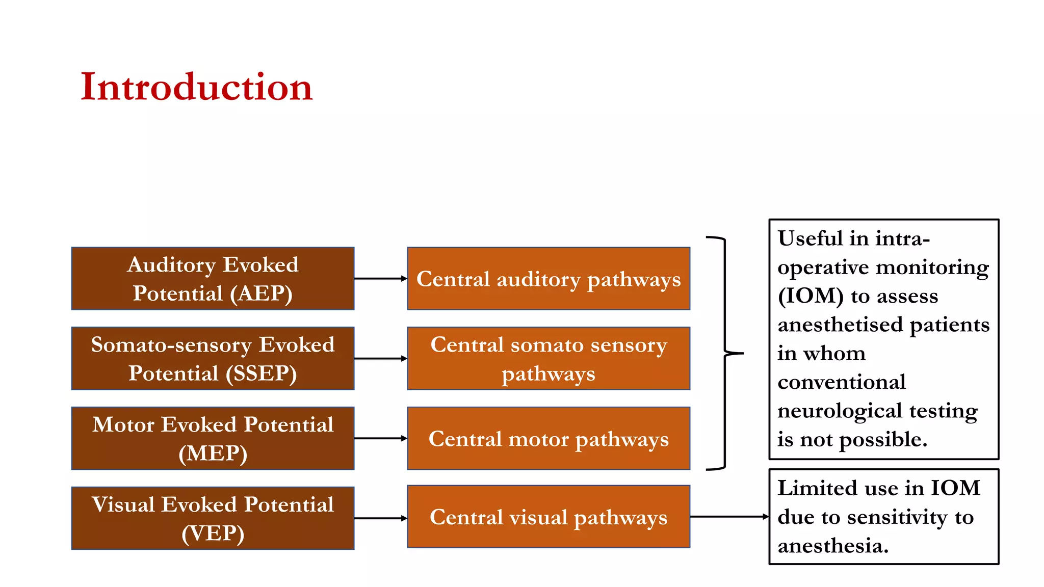
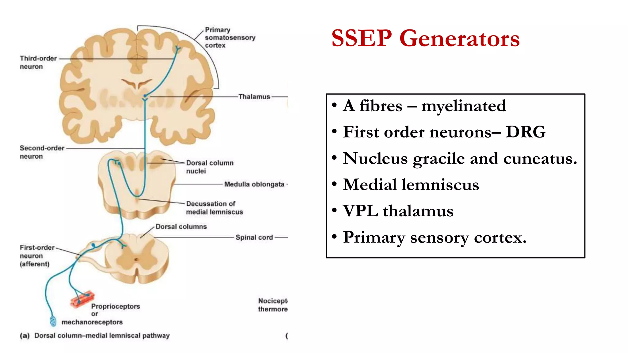
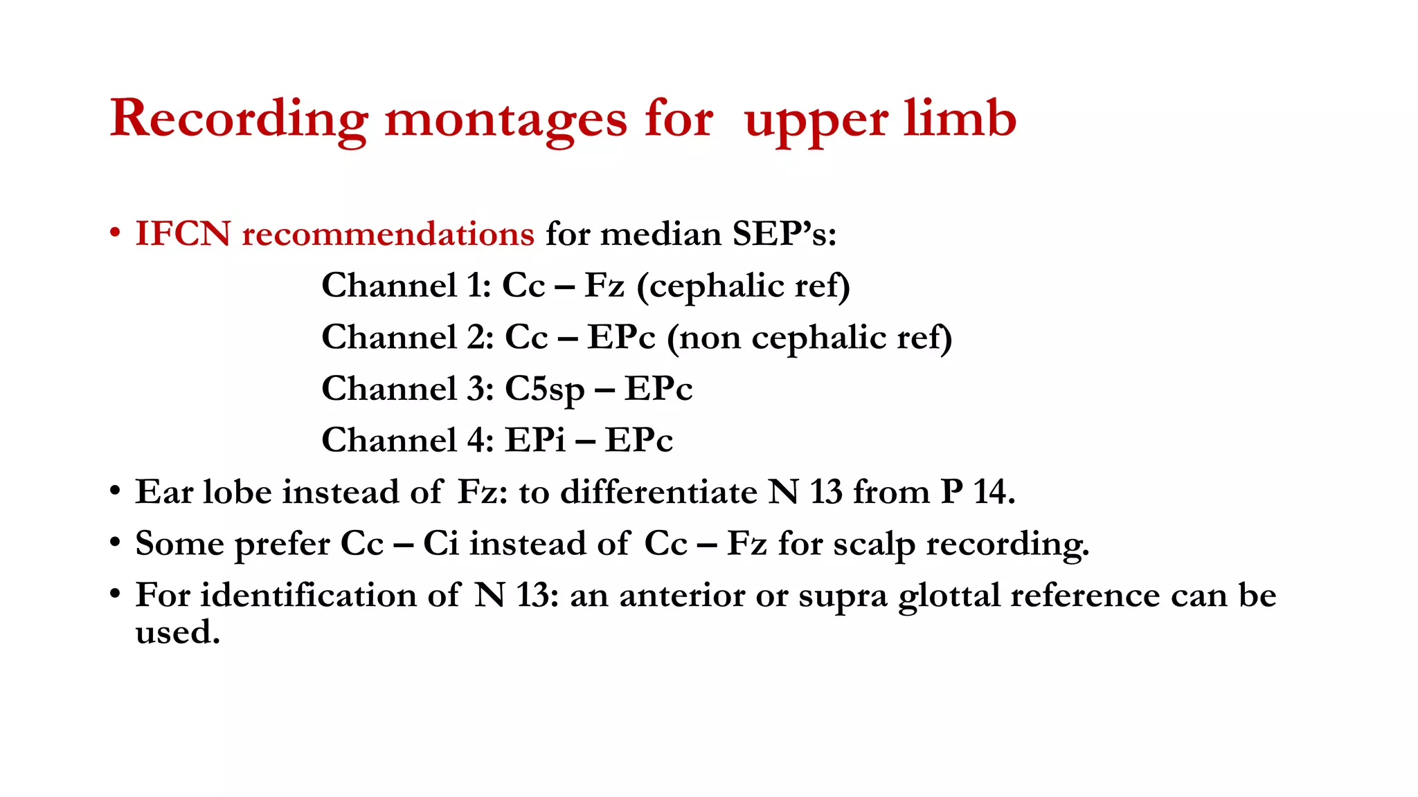
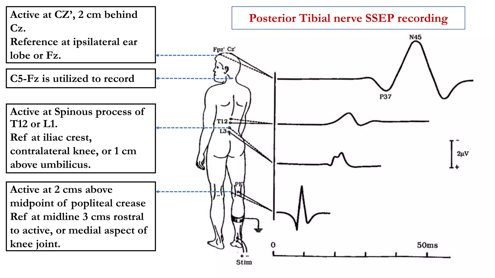
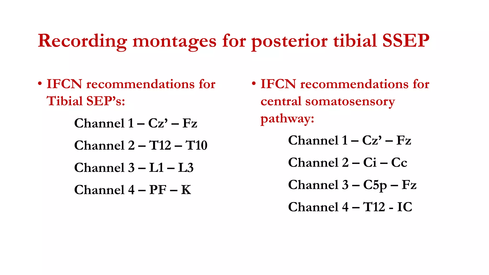
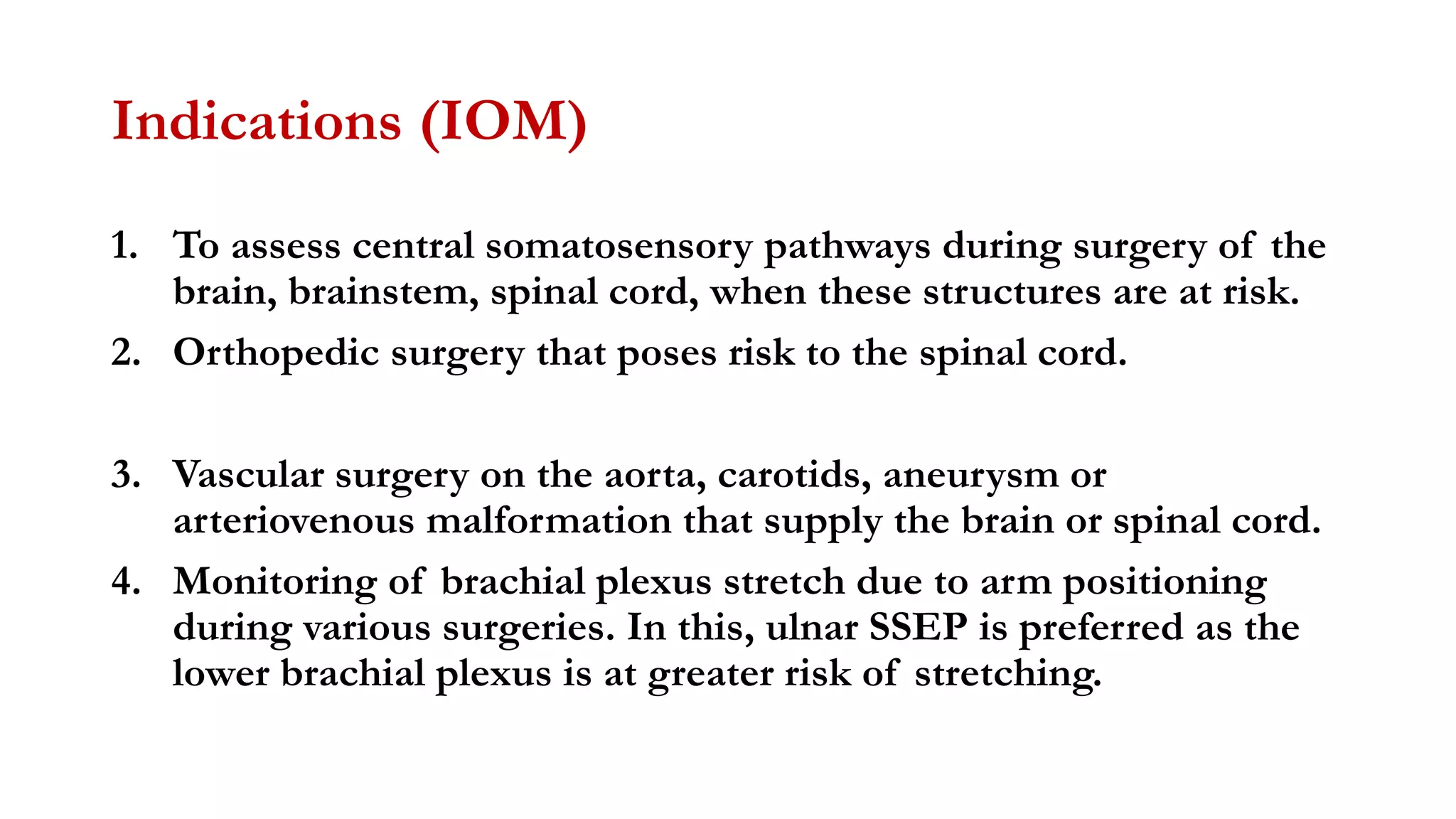
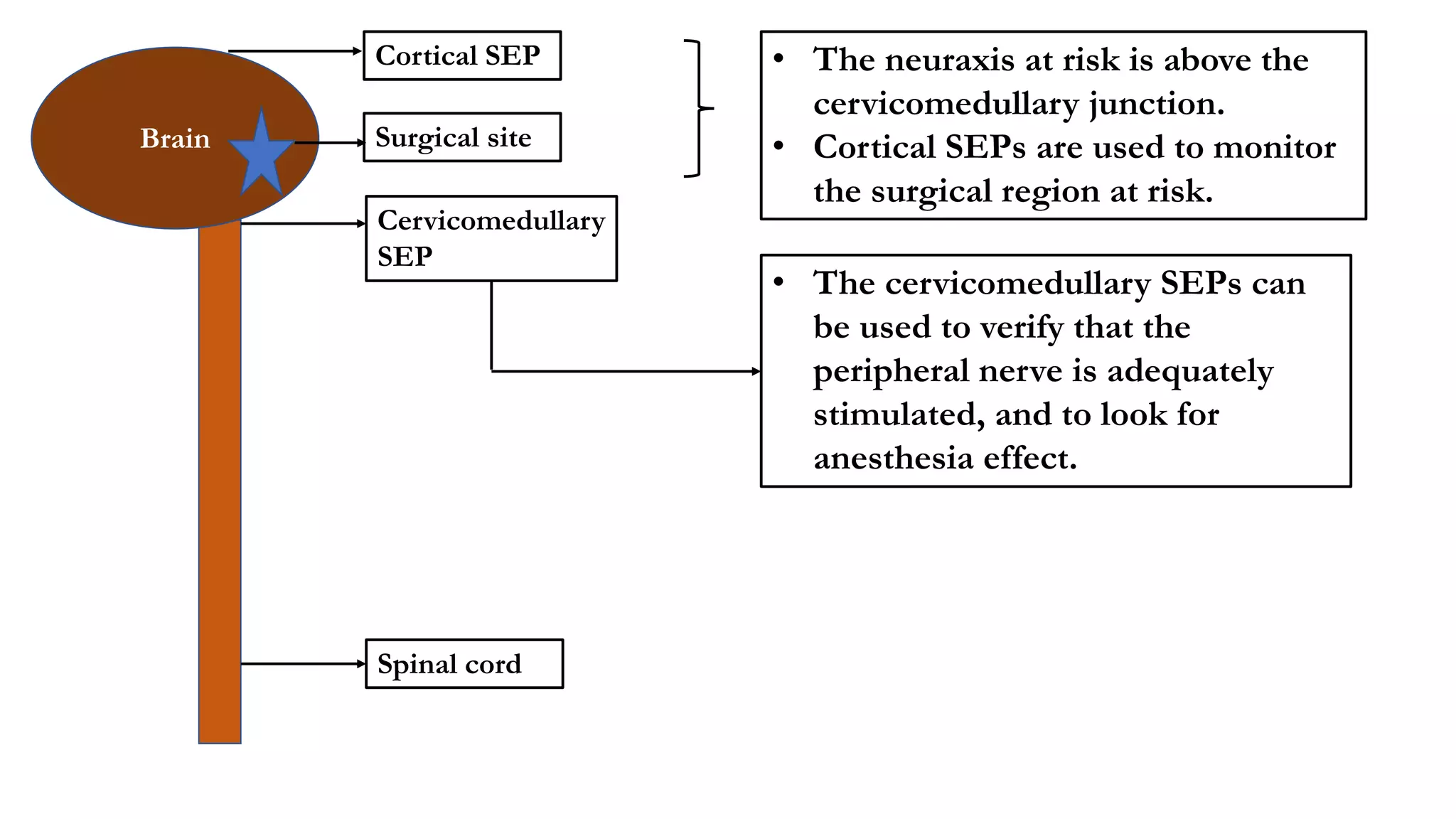
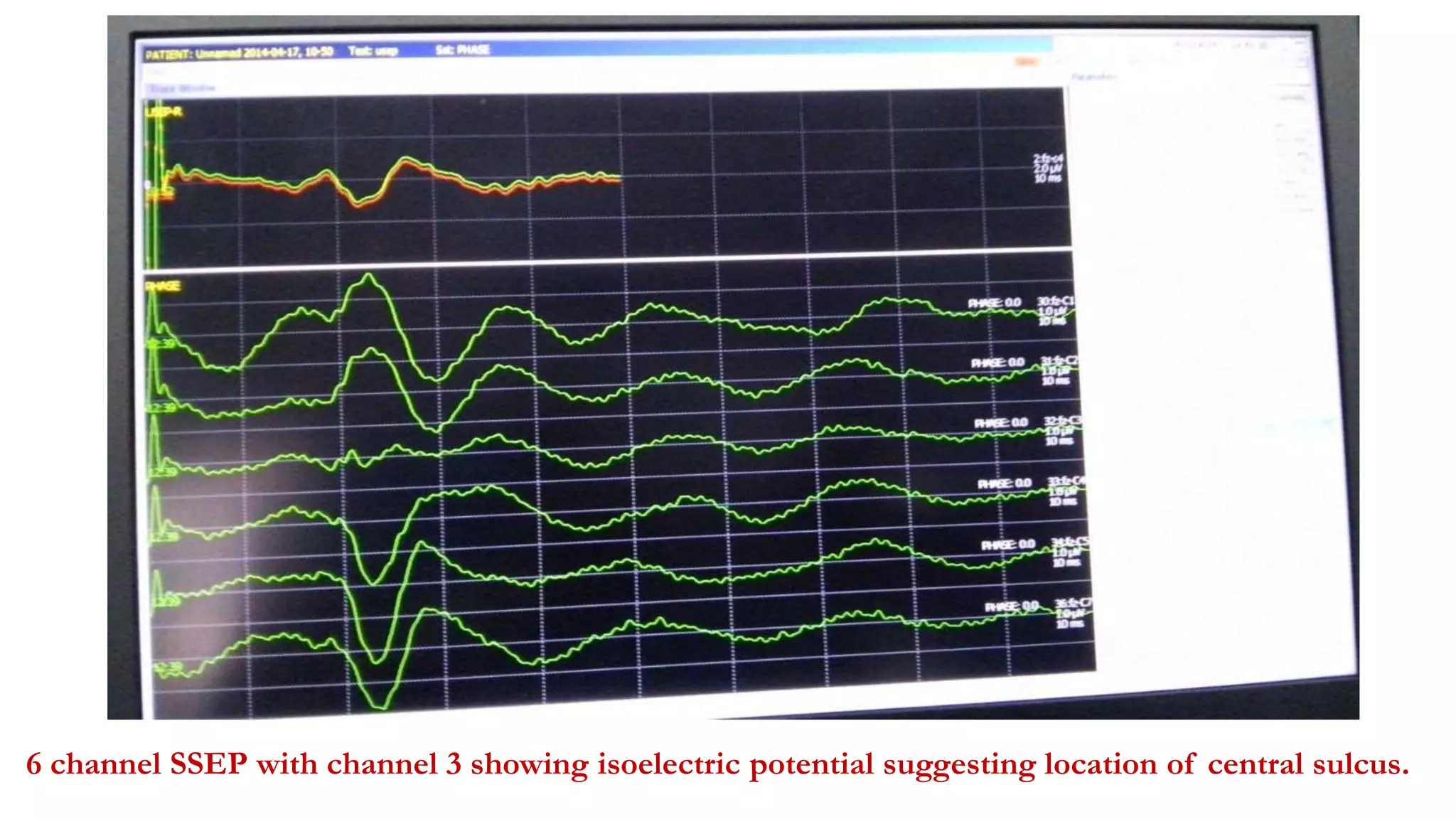
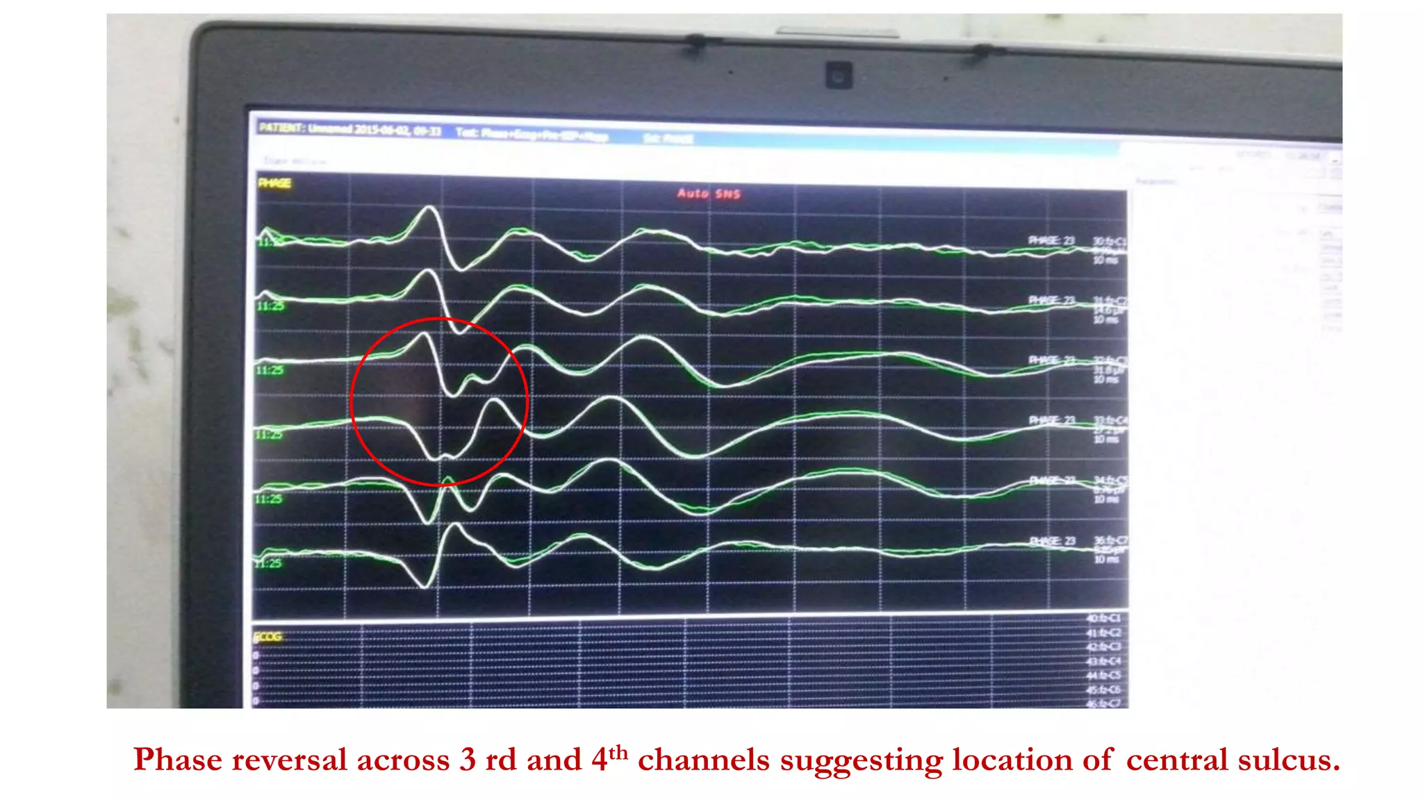
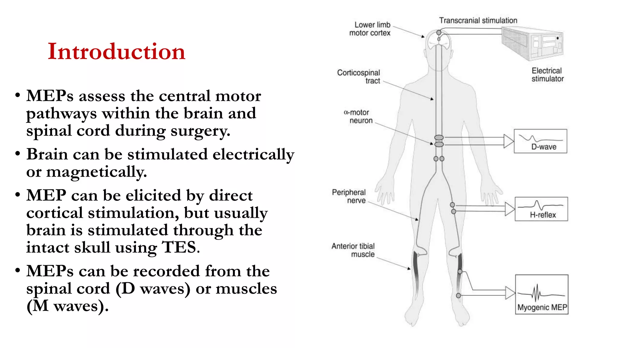
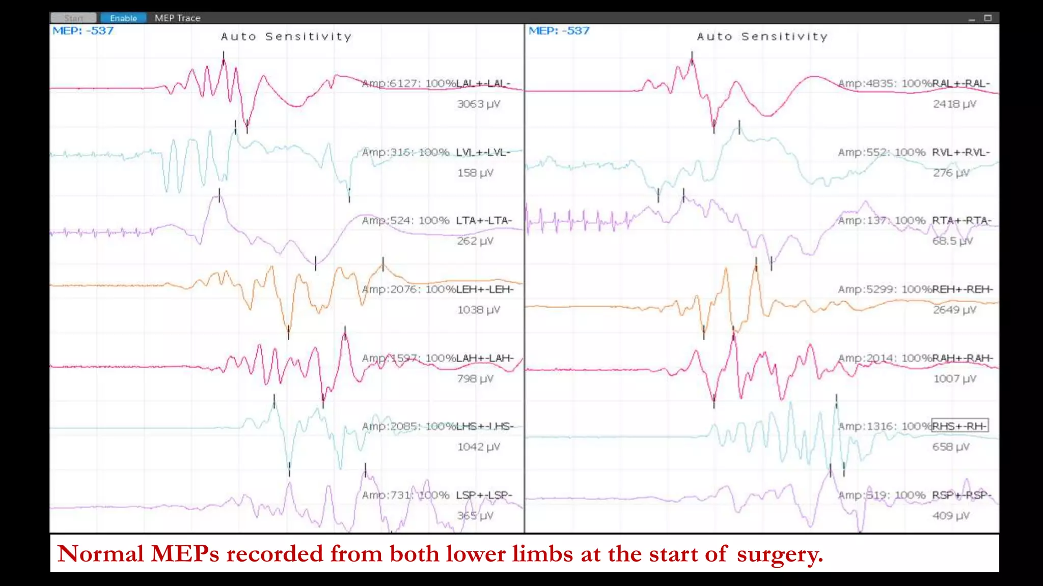
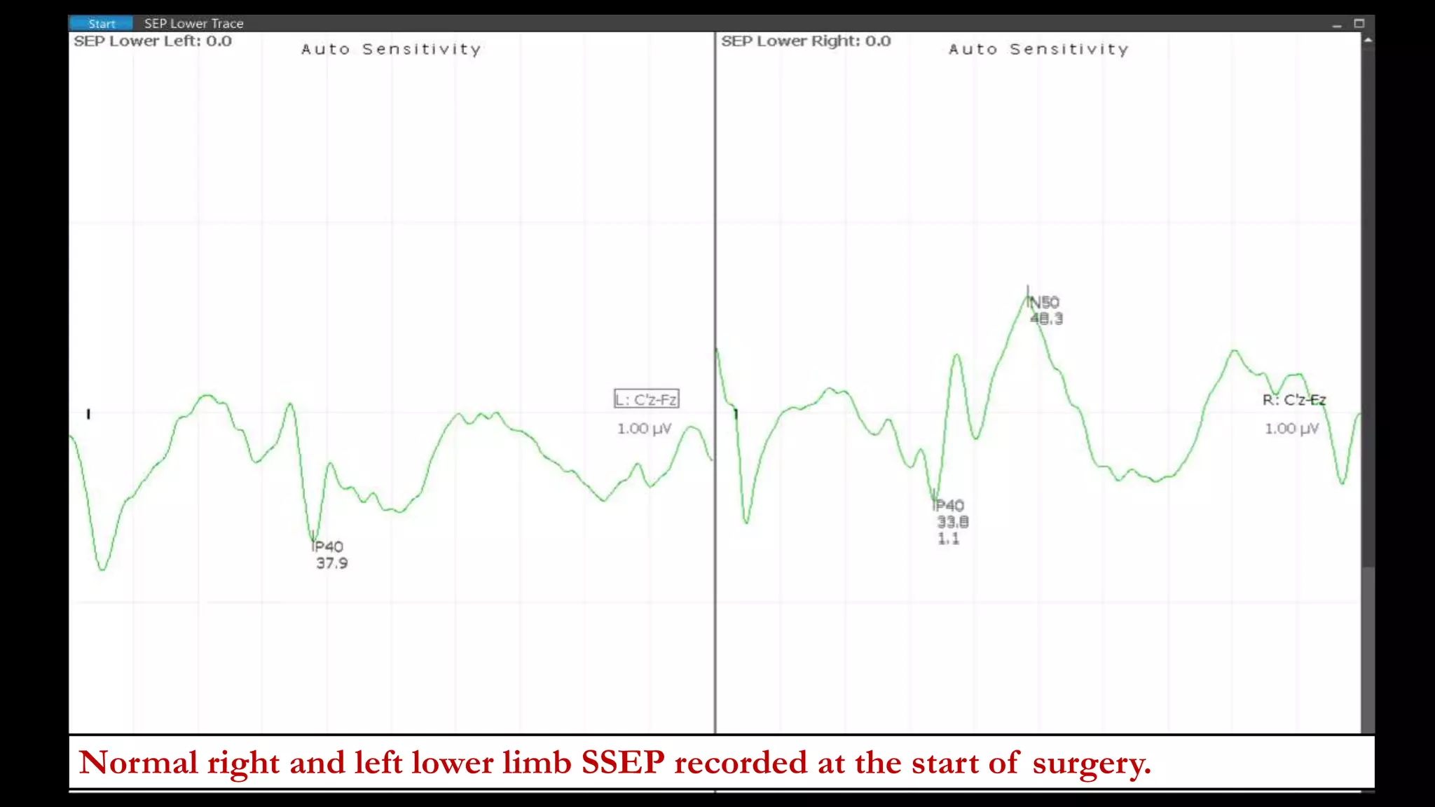
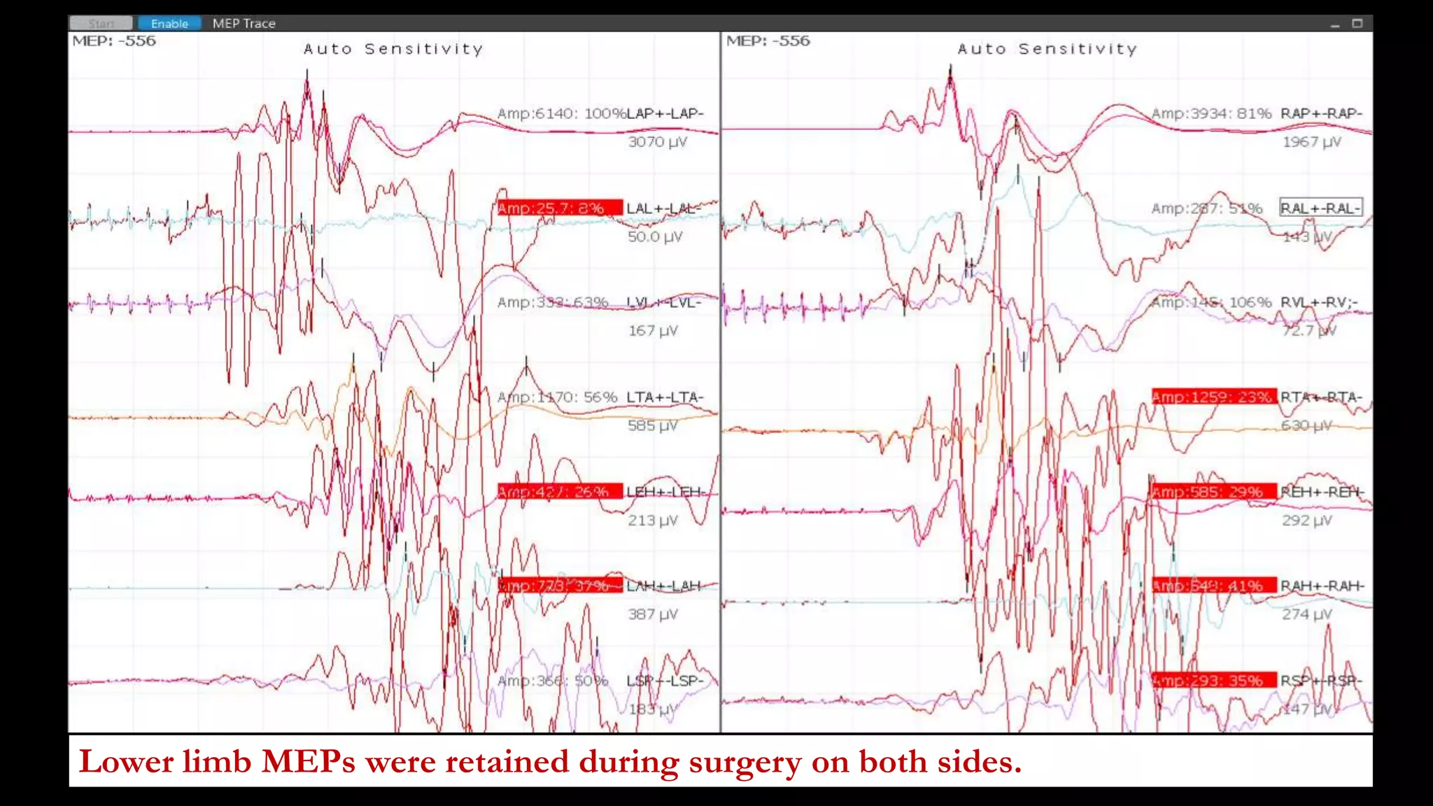
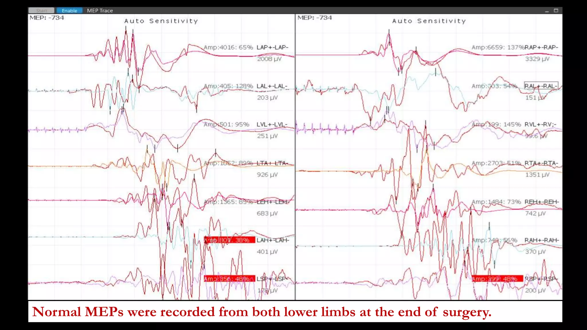
Intraoperative Evoked Potential
Monitoring
Dr Pramod Krishnan
MD (Int Med), DM Neurology (NIMHANS)
Fellowship in Epilepsy (SCTIMST), (LMU, Munich)
World Sleep Federation Certified Sleep Medicine Specialist.
Consultant Neurologist and Epileptologist
Head of the Department of Neurology,
Manipal Hospital, Bengaluru.
Introduction
Auditory Evoked
Potential (AEP)
Somato-sensory Evoked
Potential (SSEP)
Motor Evoked Potential
(MEP)
Visual Evoked Potential
(VEP)
Central auditory pathways
Central somato sensory
pathways
Central motor pathways
Central visual pathways
Limited use in IOM
due to sensitivity to
anesthesia.
Useful in intra-
operative monitoring
(IOM) to assess
anesthetised patients
in whom
conventional
neurological testing
is not possible.
I. Somatosensory Evoked
Potentials
SSEP Generators
• A fibres – myelinated
• First order neurons– DRG
• Nucleus gracile and cuneatus.
• Medial lemniscus
• VPL thalamus
• Primary sensory cortex.
Physiological basis of SSEP
• SEP stimulus excites mainly the large diameter myelinated fibers
(group Ia and II afferents) that travel through the dorsal columns.
• Number of axons activated synchronously are large which provide
large and easily recordable potentials.
• Therefore, lesions of posterior columns have the biggest impact on
SSEPs.
• The preferred method of eliciting potentials is by repeated
electrical stimulation of the peripheral nerves.
Preferred nerves
• SEPs are elicited by stimulation of the median/ulnar nerves in the
upper limbs; posterior tibial/peroneal nerves in the lower limbs.
• Median nerve is preferred over ulnar nerve, because of the
common occurrence of a degree of ulnar neuropathy at the elbow.
• Median nerve SEPs cannot monitor the spinal cord below C6, and
ulnar nerve SEPs cannot monitor the cord below C8 level.
Posterior tibial better than peroneal nerve
• Stimulation is easier; at the ankle, behind the medial malleolus.
• Posterior tibial SSEPs are typically larger.
• Electrodes at the ankle are easier to reach and replace.
• Stimulation causes less patient movement.
SSEP types
SEP types Comments.
Short latency SEP (< 10 msec) Generated in the peripheral nerves, spinal cord,
cervico-medullary junction are relatively insenstive
to anaesthetic effects and are useful in IOM.
Middle latency SEP (10- 50 msec) Primary cortical SEP, eg N20, P27, P37, are
affected by anaesthesia but can be used for IOM if
the anaesthesia is not excessive.
Long latency SEP (> 50 msec) Greatly affected by anaesthesia and are not useful
in IOM.
Therefore, in IOM, SEP can be used to monitor the central somatosensory
pathways only up through the level of the primary somatosensory cortex.
Upper limb (median nerve) SSEP components
UL SSEP Waveform Generator
N 9 Brachial plexus. Recorded at Erb’s point. Difficult to record
during surgery because of positioning, technical issues.
N 11 Dorsal cervical roots. Inconsistent. Not useful for IOM.
N 13 Gray matter of the spinal cord at the level of the root entry.
Too small and difficult to record for IOM.
P 14 Dorsal column nucleus/ cervico medullary junction. Useful
for IOM.
N 18 Subcortical white matter structures. Preserved in lesions of
the thalamus or cortex.
N 20 Primary sensory cortex. Useful for IOM.
Right median nerve SSEP
SSEP components on upper limb stimulation
Brachial plexus
Root entry zone
Cervicomedullary junction
Primary sensory cortex
Lower limb (posterior tibial) SSEP components
Waveforms Generator
N 8 Recorded from the tibial/ sciatic nerve using a midline electrode
behind the knee.
N 22 From the gray matter of the spinal cord at the level of root entry.
Limited utility in IOM because of they are too small and difficult to
record, and often close to the surgical field.
N 26 Rarely recorded over the cervical cord, due to temporal dispersion.
P 31 Dorsal column nucleus/ cervico medullary junction. Useful for IOM.
P 37 Primary sensory cortex. May be followed by N45. Useful for IOM.
P39-N50-P60 Form a W-shaped complex over the centro-parietal region.
P37 and P27 (peroneal nerve cortical SEP) are largest in the midline or over the
ipsilateral parietal area (paradoxical localisation) due to dipole orientation.
N8: Popliteal fossa
Far- field cortical
potentials
N22: Root entry
zone
P37: primary
sensory cortex
P31: Cervico-
medullary junction
• .
Normal left and right upper limb SSEP on stimulating the median nerve, showing
the N20 waveforms.
N20 N20
Normal left and right lower limb SSEP on stimulating the posterior tibial nerve,
showing the P37 and N45 waveforms.
P37
N45
P37
N45
Unilateral stimulation
• EPs should only be recorded to unilateral stimulation.
• In simultaneous bilateral stimulation, a normal EP to stimulation
of one side might prevent recognition of an abnormal or absent
EP to stimulation of the other side.
• Modern EP recording systems permit interleaving of sensory
stimuli (stimuli are delivered alternately to the left and right side).
• The data sweeps are then sorted into left and right side averages.
Normal left and right lower limb SSEP on stimulating the posterior tibial nerve,
showing the P40 and N50 waveforms.
P40 P40
Stimulation technique
• SEPs are elicited using a pair of stimulating electrodes with the
cathode proximal to prevent possibility of anodal block of the
afferent signal.
• During IOM higher stimulus intensities are used (to cover for
factors like edema) than in extra-operative studies.
• Trains of 200 μsec duration constant current pulses are used to
stimulate the nerve, with stimulus rates of 2-8/sec.
• Current strength of 5-15 mA. Impedance of less than 5 k ohm.
Surface electrodes or subdermal needle stimulating electrodes (directed away from
each other) with spacing of 3 cm are used for stimulation.
Recording techniques
• LFF of 5-30Hz; HFF of 1000- 3000 Hz.
• Avoid notch filters as they can cause a ‘ringing’ oscillatory artefact.
• Epoch (sweep) duration: atleast twice the latency of the longest
EP component of interest.
• Epoch duration for upper limb: 50 msec; lower limb: 80-100 msec.
• Number of sweeps per average (depends on SNR): 200-2000.
• Recording electrodes can also be placed directly on the cortex or
spinal cord for better signals.
• Recording electrodes are
placed at C3’ and C4’
(between C3 and P3, and
C4 and P4 respectively).
• Recording electrodes at
right and left Erbs point,
C5 spinous process.
• Fz is the reference
electrode.
• P14, N18 and N20 should
be studied.
Monitoring cervical spinal cord
Recording montages for upper limb
• IFCN recommendations for median SEP’s:
Channel 1: Cc – Fz (cephalic ref)
Channel 2: Cc – EPc (non cephalic ref)
Channel 3: C5sp – EPc
Channel 4: EPi – EPc
• Ear lobe instead of Fz: to differentiate N 13 from P 14.
• Some prefer Cc – Ci instead of Cc – Fz for scalp recording.
• For identification of N 13: an anterior or supra glottal reference can be
used.
Active at 2 cms above
midpoint of popliteal crease
Ref at midline 3 cms rostral
to active, or medial aspect of
knee joint.
Active at Spinous process of
T12 or L1.
Ref at iliac crest,
contralateral knee, or 1 cm
above umbilicus.
Active at CZ’, 2 cm behind
Cz.
Reference at ipsilateral ear
lobe or Fz.
C5-Fz is utilized to record
Posterior Tibial nerve SSEP recording
Recording montages for posterior tibial SSEP
• IFCN recommendations for
Tibial SEP’s:
Channel 1 – Cz’ – Fz
Channel 2 – T12 – T10
Channel 3 – L1 – L3
Channel 4 – PF – K
• IFCN recommendations for
central somatosensory
pathway:
Channel 1 – Cz’ – Fz
Channel 2 – Ci – Cc
Channel 3 – C5p – Fz
Channel 4 – T12 - IC
Indications (IOM)
1. To assess central somatosensory pathways during surgery of the
brain, brainstem, spinal cord, when these structures are at risk.
2. Orthopedic surgery that poses risk to the spinal cord.
3. Vascular surgery on the aorta, carotids, aneurysm or
arteriovenous malformation that supply the brain or spinal cord.
4. Monitoring of brachial plexus stretch due to arm positioning
during various surgeries. In this, ulnar SSEP is preferred as the
lower brachial plexus is at greater risk of stretching.
Clinical utility in routine diagnostics
• Peripheral neuropathies and radiculopathies like GBS.
• Brachial plexopathy.
• Demyelinating diseases of the CNS: eg Multiple sclerosis.
• Ataxic disorders.
• Syringomyelia.
• Traumatic CNS injuries.
• Prognostication after severe cerebral insult like HIE.
• Progressive myoclonic epilepsy: giant SSEP.
Measurements
1. Latency: onset or peak latency.
2. Amplitude: measured from peak
to trough.
3. Inter peak latency (IPL): to
measure conduction at various
segments. Most centres consider
latencies within 3 SDs of the mean
to be within normal limits.
4. Central sensory conduction time
(CSCT).
Stimulus N 9 N 13 P 14 N 20N 11 N 18
• Abnormal N9-N13 IPL: conduction defect between brachial plexus to lower
medulla. Eg: Radiculopathy.
• N13-N20 IPL: Central Sensory Conduction Time (CSCT). If abnormal, defect is
between root entry zone to primary sensory cortex.
• Bilateral absent N20 is a poor prognostic marker in coma, eg HIE.
• N9 not recordable but other waveforms are normal – Normal.
• N9 absent and absolute latencies are prolonged – Peripheral nerve.
• N9- N13 helps to evaluate proximal brachial plexus.
• P14-N20: intracranial conduction time.
Stimulus N 8 N 26 P 31 P37N 22
• Prolonged or absent N8, N22: severe peripheral neuropathy.
• N22- P37: Central Sensory Conduction Time (CSCT).
• Prolonged N22-P37 IPL, median nerve SSEP abnormal: lesion between cauda
equina and cortex.
• N22- P31: intraspinal conduction time.
• Inferior displacement of N22 recording site: e.g. tethered cord.
• P31-P37: intracranial conduction time.
• Prolonged N22-P37 IPL, median nerve SSEP normal: between cauda equina
and C6 level of cord.
Assessment of IOM data
• Interpretation of extra operative EP studies is mainly based on
latencies as amplitudes vary substantially across subjects.
• However, component amplitudes on repeated recordings in the
same subject are usually quite consistent.
• Amplitude changes occur earlier than, or without latency changes.
• Therefore, both the amplitudes and latencies should be assessed.
• Typical alarm criteria are a 50% drop in component amplitudes
and a 10% increase in component latencies.
Causes of adverse EP changes
1. True positive changes: which reflect compromise of the
structures that is being monitored, due to:
• Mechanical injury.
• Thermal injury
• Ischemic injury: vasospasm, occlusion, generalised hypotension.
• Combination of these factors.
1. Changes due to anesthetic effects, hypothermia, etc.
2. Changes due to technical problems, operator error.
Assessment of IOM data
Rostral SEP
absent
Check CMAP CMAP presentAbsent CMAP
Compromise of afferent
somatosensory pathway due
to surgery. Notify surgeon.
Technical factors,
limb ischemia,
limb compression
Brain
Cortical SEP
Cervicomedullary
SEP
Surgical site
Spinal cord
If the neuraxis at risk is caudal to
the cervico-medullary junction (e.g.
spinal cord), either the primary
cortical or cervicomedullary SEP
can be used for IOM.
Brain
Cortical SEP
Cervicomedullary
SEP
Surgical site
Spinal cord
• The cervicomedullary SEPs can
be used to verify that the
peripheral nerve is adequately
stimulated, and to look for
anesthesia effect.
• The neuraxis at risk is above the
cervicomedullary junction.
• Cortical SEPs are used to monitor
the surgical region at risk.
Adverse changes due to anesthesia
• Increased anesthetic effect can cause attenuation and latency
prolongation of the cortical SEPs, mimicking tissue compromise.
• Presence of adequate cervicomedullary SEPs can be used to
determine if the cortical SEP changes are due to anesthetic effect.
• If the anesthetic dose or regimen is significantly altered during
surgery, the baseline amplitude and latency should be reassessed.
• Such anesthetic changes should be avoided during critical stages
of the monitoring.
Technical causes of abnormal findings
• If the constant current SEP stimulator is unable to deliver a preset
current level, the IOM equipment will indicate high impedence or
open-circuit stimulus condition (e.g. broken wires, dislodged
electrodes).
• If the paired stimulating electrodes are short circuited together, as
by a salt bridge, the nerve will not be stimulated effectively, the
SEP will deteriorate, but the equipment will not indicate any error.
Limitations
• The rostral SEPs used for IOM are mediated almost entirely by the
dorsal columns (because the spinothalamic tracts have slower
conduction velocity and temporal dispersion).
• The SEPs therefore assess only that portion of the spinal cord
supplied by the posterior spinal artery.
• SEP monitoring may rarely fail to detect ischemic or mechanical
spinal cord injury limited to the anterior cord.
Case 1
• 17yr/Female.
• Progressive deformity of the back of 5 years duration.
• Normal birth and development. Twin has similar deformity.
• No history of trauma, respiratory symptoms or limb weakness.
• Diagnosis: Adolescent idiopathic thoracic scoliosis: Lenke Type I;
Kings Type III with convexity to the right.
• Main thoracic Cobbs Angle: 67 Degrees, with Lumbar
compensatory curve.
Pre Op X-rays
TcMEP stimulators
C4’
C3’
Cz’
Fz
Arrangement of recording and stimulating electrodes. Cz’ is the recording electrode for LL
SSEP. C3’ is the recording electrodes for right UL and C4’ for left UL stimulated SSEP
respectively. TcMEP are transcranial stimulators for MEP (C1, C2).
C1
C2
Normal left and right upper limb SSEP on stimulating the median nerve, showing the N20
waveforms, at the start of surgery.
N20 N20
Normal left and right lower limb SSEP on stimulating the posterior tibial nerve, showing
the normal waveforms, at the start of surgery.
P37
P37
Baseline
Normal left and right lower limb SSEP on stimulating the posterior tibial nerve, showing
the normal waveforms, at the end of surgery.
Baseline
Normal left and right upper limb SSEP on stimulating the posterior tibial nerve, showing
the normal waveforms, at the end of surgery.
Post-Op X rays of thoracic spine
Follow up
• Her shoulders were at same level, pelvis was squared and she was
standing in erect posture and walking with normal gait.
• Post op X-ray showed correction of thoracic deformity with
residual deformity of 25 degrees and her shoulders and pelvis were
at same level.
• No neurological deficits.
• Doing well; 2 years of follow up.
Central sulcus mapping
• Surgeries involving fronto-
parietal cortex.
• After exposure of the cortex,
record using 6 or 8 contact strip
across the central sulcus (active
electrode).
• Contra-lateral median nerve is
stimulated.
• Reference electrode placed at
FpZ, ground electrode on the
hand.
P20
N20
P20
N20
The N20/P20 waveforms are recorded over the somatosensory cortex, whereas waves of
the opposite polarity, are recorded over the primary motor cortex. Area of highest
amplitude of N20 and P20 corresponds to the hand areas of the sensory and motor
cortex respectively, and the location of phase reversal corresponds to the central sulcus.
Phase reversal across 3 rd and 4th channels suggesting location of central sulcus.
6 channel SSEP with channel 3 showing isoelectric potential suggesting location of central sulcus.
Phase reversal across 3 rd and 4th channels suggesting location of central sulcus.
II. Auditory Evoked
Potentials
Indications
1. BAEPs can be used for IOM of the VIIIth nerve, infratentorial
auditory pathways up through the level of the mesencephalon.
2. Vestibular Schwannomas.
3. Tumors or vascular abnormalities of the posterior fossa, both
extra-axial and within the brainstem.
4. Useful in detecting VIIIth nerve stretch during surgery.
AEP types
AEP Characteristics
Short latency (<10 ms) Minimally affected by anesthesia. Useful for IOM. Relatively
easy to record and have consistent waveforms. Most of the
components are generated in the brainstem auditory pathways;
hence called brainstem auditory evoked potentials (BAEPs).
Middle latency (10-50 ms) Generated within cerebral cortex, primary auditory cortex and
surrounding areas. Markedly affected by anesthesia; so not
useful for IOM. Can be used as an indicator of the depth of
anesthesia.
Long latency (>50 ms) Generated within the cerebral cortex, association areas.
Suppressed by anesthesia; so not useful for IOM.
Stimulation techniques
• Acoustic stimuli are delivered using ear inserts. It is connected to
an acoustic transducer.
• Acoustic clicks, produced by delivering trains of 100 μsec duration
electrical square pulses to the acoustic transducer are used for
BAEP.
• Stimulus rate of 10/sec.
Ear inserts for stimulation
Recording BAEPs
• Filter settings: LFF of 100-150 Hz; HFF of 3000 Hz.
• Notch filter can be used.
• Epoch duration: 15 ms.
• Sweep speed: 1000-2000
• Positive BAEP peaks are displayed as upward deflections (unlike
EEG, SEP), and labelled with roman numerals.
• BAEP potentials, except Wave I are far field potentials, so minor
changes in electrode positions do not alter the waveform.
Wave II: often absent. Arises from proximal auditory nerve, cochlear nucleus.
Wave I: present ipsilaterally. Arises from distal auditory nerve.
Wave III: should be detectable in all healthy individuals. It is bilateral, but lower amplitude
on the contralateral side. Arises from caudal pontine tegmentum, superior olivary complex.
Wave IV: Forms a complex with wave V. Reflects activity in the dorsal and rostral pons.
Wave V: Bilateral, should be detectable in all healthy individuals. Reflects activity in the inferior
colliculus and rostral portion of the lateral lemniscus.
Wave VI and VII: variable, often absent. Reflects activity in more rostral structures like MGB.
Normal BAEP waveforms seen during IOM: Waves I, II, III and IV-V complex.
Assessment of IOM data
• The peak latencies of waves I, III, V are measured, and the
amplitude of each of these components is measured with respect
to the trough that follows it.
• Central transmission time (wave I-V interval) can be measured.
• Typical alarm criteria are a 50% drop in component amplitudes
and a 1 ms increase in component latencies or in the central
transmission time.
Finding Interpretation
Loss or delay of wave I and subsequent
waves
Cochlear dysfunction due to ischemia,
infarction.
Wave 1 preserved, but loss or delay of
wave III, V
Compromise of the proximal VIIIth nerve or
lower pons.
Wave 1 and III preserved, but loss or
delay of wave V
Compromise of auditory pathways within the
brainstem, between the lower pons and the
mesencephalon.
If the BAEP findings are unilateral or asymmetrical, the predominant
pathology is most often ipsilateral to the ear whose stimulation gives the most
abnormal BAEPs.
Internal auditory artery compromise
• Cochlea is supplied by the internal auditory artery, a branch of the
AICA, and passes through the internal auditory canal alongside
the VIII th nerve.
• Damage to this artery will cause cochlear ischemia/ infarction and
cause loss or delay of wave I and all subsequent BAEP waves.
• This is the most common cause for loss of all BAEP components
during surgery.
VIII th nerve stretch
• During retraction of cerebellum to gain access to the CP angle, the
VIII th nerve can get stretched, leading to hearing loss.
• BAEP monitoring can be used to detect excessive VIII th nerve
stretch and to notify surgeons that the retraction needs to be
reduced or readjusted.
Motor Evoked Potentials
Introduction
• MEPs assess the central motor
pathways within the brain and
spinal cord during surgery.
• Brain can be stimulated electrically
or magnetically.
• MEP can be elicited by direct
cortical stimulation, but usually
brain is stimulated through the
intact skull using TES.
• MEPs can be recorded from the
spinal cord (D waves) or muscles
(M waves).
Indications
1. To monitor the integrity of the corticospinal tract (CST) during
surgery on the brain, brainstem or spinal cord.
2. Orthopedic surgery that poses risk to the spinal cord.
3. Surgery on the aorta or other vessels that supply the brain or
spinal cord.
4. To assess the function of cranial nerves or spinal nerve roots by
recording MEPs in the muscles they innervate.
Normal MEPs (M waves) recorded from the right and left lower limbs following
transcranial electrical stimuation.
MEP waves
M waves D waves
Most sensitive to anesthesia among all EPs, due
to anesthetic effects on anterior horn cell.
Insensitive to anesthetic effects as there are
no intervening synapses.
Attenuated by neuromuscular blockade (NMB). Not attenuated by NMB.
Variable morphology. More consistent from run to run.
Surface or needle electrodes placed in the
muscles of interest.
Invasive electrodes placed in epidural space
placed percutaneously using a Touhey needle.
Can be used to monitor lower spinal cord. Not useful.
May show changes earlier than D waves. Changes may be delayed after M wave.
Useful when D waves are not recordable due to
pre-existing cord pathology which has
desynchronised the descending CST volley.
Useful when M waves are not recordable due
to pre-existing nerve pathology or anesthetic
effects.
2 contact D wave electrode and its placement in
the epidural space.
D wave recording during spinal cord surgery. Red is the baseline. White is the
current averaged D wave. Green is the last averaged D wave.
Normal right and left MEPs- M waves (upper half of figure) along with D waves
(lower half) recorded from the lower limbs and spinal cord respectively.
Normal right and left lower limb MEP M waves, along with D waves (upper half) along
with lower limb SSEP (lower half).
Stimulation techniques
• High intensity, multipulse stimulator is used to produce multiple
closely spaced descending volleys in the CST, so that temporal
summation of EPSPs they produce fire the AHCs.
• 3-7 stimulus pulses per train.
• Interpulse intervals of 2-4 msec within the train.
• Wide open filters (e.g. 5 to 3000 Hz).
• Each stimulus activates a small pool of AHCs. The subset of
AHCs activated varies with each stimulus. So, M wave morphology
also changes from run to run.
Stimulation using cockscrew electrodes and recording from
muscles using needle electrodes.
Recording techniques
• M waves have good amplitude; signal averaging is not required.
• D waves are smaller and signal averaging of a small number of
sweeps (5-25) is useful.
• As there is no intervening synapse, pulse train stimulation is not
used for D waves. Therefore less chance of patient movement
during stimulation.
• TES stimulus intensity should be kept to a level that produces
MEPs in one limb only.
Assessment of MEP data
• For D waves, 50% drop in amplitude or 10% increase in latency is
the alarm criteria.
• For M waves, in view of varying morphology, complete absence, or
greater than 75% drop in amplitude is the alarm criteria.
• For assessing M waves, anesthesia regimen should be considered.
• For prolonged surgeries, MEP amplitudes tend to decrease, and
threshold to elicit MEP tends to rise (anesthetic fade). In such
cases, MEP baseline should be reassessed.
Adverse MEP changes
• Direct mechanical, thermal or ischemic injury.
• Anesthesia and NMB affects M waves. Total intravenous
anesthesia without inhalational agents is best to record MEP.
• M waves can be recorded during partial NMB, but the NMB
should be maintained by a continuous infusion of paralytic drug
than intermittent bolus dose.
• If the spinal cord below the neck is at risk, upper limb MEP can
be used as controls to identify anesthesia effects.
Case 2
• 6 Yr/ Male.
• Cerebral palsy with mental subnormality, spastic quadriparesis.
• Focal epilepsy.
• Hand functions are impaired due to spasticity. Severe lower limb
spasticity without response to botulinum toxin and physiotherapy.
• Flexor spasms present; ankles plantar flexed posture.
• Brisk DTRs, Clonus in Lower limbs.
• Overall Gross Motor Function Classification System score - Level 4
Modified Ashworth Score for spasticity
Upper limb Left Right
Shoulder 0 0
Elbow flexion 0 1
Elbow extension 3 2
Wrist 0 0
Lower limb Left Right
Hip abduction 0 0
Hip adduction 0 2
Hip flexion/ Ext 0 0
Knee flexion 3 2
Knee extension 0 1
Ankle dorsiflexion 0 0
Ankle plantar flexion 2 2
Right and left MEP recorded from the lower limbs during dorsal rhizotomy. Poorly formed
MEP waveforms at the start of surgery.
Right and left MEP recorded from the lower limbs during dorsal rhizotomy. Well formed
MEP waveforms at the end of surgery.
loss
Left and right lower limb SSEP recorded with posterior tibial nerve stimulation. Poorly
formed SSEP on the right side.
Post-Op Ashworth Score for spasticity
Upper limb Left Right
Shoulder 0 0
Elbow flexion 0 0
Elbow extension 2 2
Wrist 0 0
Lower limb Left Right
Hip abduction 0 0
Hip adduction 0 2
Hip flexion/ ext 0 0
Knee flexion 3 0
Knee extension 0 1
Ankle dorsiflexion 0 0
Ankle plantar flexion 2 1
Case 3
• 37 year/ Female.
• Neuromuscular kyphoscoliosis (poliomyelitis at age 10 years) with
Cobb's angle 130 degrees.
• Restrictive lung disease and Interstitial fibrosis.
• Significant weakness and wasting of predominantly left sided
limbs.
• Progressive deformity of back since age of 10 years and disability.
• Progressive difficulty in sitting without support and walking since
the past 3 years. No bowel or bladder involvement.
Pre-Op Xray
Normal right and left MEP recorded from the lower limbs at the start of surgery.
After fixing screws on the left, there was a drop in left sided MEP amplitudes.
After fixing iliac screws there was a slight drop in right sided MEPs, while the left sided
MEPs remained absent. Recordings from anal sphincter were normal.
After removing a few screws, there was no improvement in right sided or left sided
MEPs.
After placing rod on the left side, right sided MEPs reduced markedly. Left sided MEPs
remained absent. Anal sphincter activity remained normal throughout on both sides.
After placing rods on both sides, the MEPs remained the same.
At the end of surgery, barely detectable MEPs were noted on the right side and absent
MEPs on the left side. Good anal sphincter activity was noted on both sides.
Follow up
• Had severe paraparesis after surgery.
• Required significant physiotherapy post op.
• Had prolonged hospitalization following post-op sepsis, worsening
of lung function requiring home oxygenation therapy.
• Poor neurological outcome.
• Lost to follow-up.
Case 4
• 9 years/ Male.
• Normal birth and development.
• Myelomeningocele with spina bifida at S1, S2 levels and tethered
cord.
• Swelling over the lower back since birth, which is gradually
increasing in size.
• Pain over the swelling for the last 6 months, with intermittent
discharge.
• No limb weakness or sphincter disturbance.
Spina bifida at S1, S2 level with meningomyelocele with tethered cord syndrome.
Normal MEPs recorded from both lower limbs at the start of surgery.
Normal right and left lower limb SSEP recorded at the start of surgery.
Lower limb MEPs were retained during surgery on both sides.
Normal MEPs were recorded from both lower limbs at the end of surgery.
Follow Up
• No Intraoperative and post operative complications.
• No deficits post op.
• Doing well 1 year post op.
Case 5
• 19 years/female, with insidious onset,
progressively increasing deformity of
the back for 6 months.
• Numbness in all limbs.
• Diagnosis: Adolescent Idiopathic right
thoracic scoliosis with Cobbs angle 40
degrees. Lenke 1A.
• Surgery: T4-L1 posterior corrective
instrumentation and fusion and
multiple facetectomy.
Normal baseline MEP recording on the right and left side at the start of surgery.
Improved MEP amplitudes noted on both sides as surgery progresses.
Improvement in MEP amplitudes persisted all through the surgery.
Final recording at the end of surgery showed improvement in the amplitudes, better than
baseline levels.
Upper and lower limb SSEPs remained normal throughout the surgery.
Follow up
• Uneventful post-operative
period. No deficits.
• Underwent physiotherapy
for 6 months. Doing well
at 6 months follow up and
has no deficits.
Case 6
• 1 year 8 month old male child.
• Normal birth and development.
• Swelling over the lower back since birth that is progressively
increasing in size over the last 1 month.
• Fever for the last 5 days. Not able to walk since then.
Diagnosis: Neurocutaneous dermoid sinus at S3 and infected
intradural intramedullary epidermoid cyst L2-S2 with focal
diastematomyelia with cord edema, syrinx extending till D11.
Normal MEPs are recorded from both lower limbs at the beginning of surgery.
>50% drop in MEP amplitude recorded from the right and left vastus lateralis
and left tibialis anterior during the surgery.
Final recording at the end of surgery continued to show drop in amplitude recorded
from the right and left vastus lateralis and left tibialis anterior during the surgery.
Normal upper limb SSEP but poorly formed lower limb SSEP waveforms from
right side at the beginning of surgery.
Lower limb SSEP remained the same at the end of surgery, and did not show any
deterioration.
Follow up
• Mild weakness of both lower limbs following surgery.
• Recovered well with time.
• Normal motor function of the lower limbs on follow up.
Somatosensory (SEP) and motor evoked potential (MEP) recording.
Important consideration
• MEPs monitor the integrity of the CST (anterolateral cord).
• SEPs monitor the integrity of the dorsal columns (posterior cord).
• Therefore, for monitoring the spinal cord during surgery, both SEP
and MEP should be used. This also provides a measure of
redundancy.
• For spinal cord surgery below C8, upper limb SSEP and MEP
should also be recorded to serve as control.
Conclusion
• Intraoperative evoked potentials are a reliable and effective means
to monitor the central somato-sensory, auditory and motor
pathways during surgery of the brain, brainstem and spinal cord.
• Combining multiple modalities provides for redundancy and
increases the chance of identifying tissue compromise and
classifying technical and anesthesias related changes.
• Increased training of neurologists, neurotechnologists and
increased awareness amongst surgeons and anaesthetists is
required to enhance the scope and efficacy of IOM.
THANK YOU

Intraoperative Evoked Potential Monitoring

  • 1.
    Intraoperative Evoked Potential Monitoring DrPramod Krishnan MD (Int Med), DM Neurology (NIMHANS) Fellowship in Epilepsy (SCTIMST), (LMU, Munich) World Sleep Federation Certified Sleep Medicine Specialist. Consultant Neurologist and Epileptologist Head of the Department of Neurology, Manipal Hospital, Bengaluru.
  • 2.
    Introduction Auditory Evoked Potential (AEP) Somato-sensoryEvoked Potential (SSEP) Motor Evoked Potential (MEP) Visual Evoked Potential (VEP) Central auditory pathways Central somato sensory pathways Central motor pathways Central visual pathways Limited use in IOM due to sensitivity to anesthesia. Useful in intra- operative monitoring (IOM) to assess anesthetised patients in whom conventional neurological testing is not possible.
  • 3.
  • 4.
    SSEP Generators • Afibres – myelinated • First order neurons– DRG • Nucleus gracile and cuneatus. • Medial lemniscus • VPL thalamus • Primary sensory cortex.
  • 5.
    Physiological basis ofSSEP • SEP stimulus excites mainly the large diameter myelinated fibers (group Ia and II afferents) that travel through the dorsal columns. • Number of axons activated synchronously are large which provide large and easily recordable potentials. • Therefore, lesions of posterior columns have the biggest impact on SSEPs. • The preferred method of eliciting potentials is by repeated electrical stimulation of the peripheral nerves.
  • 6.
    Preferred nerves • SEPsare elicited by stimulation of the median/ulnar nerves in the upper limbs; posterior tibial/peroneal nerves in the lower limbs. • Median nerve is preferred over ulnar nerve, because of the common occurrence of a degree of ulnar neuropathy at the elbow. • Median nerve SEPs cannot monitor the spinal cord below C6, and ulnar nerve SEPs cannot monitor the cord below C8 level.
  • 7.
    Posterior tibial betterthan peroneal nerve • Stimulation is easier; at the ankle, behind the medial malleolus. • Posterior tibial SSEPs are typically larger. • Electrodes at the ankle are easier to reach and replace. • Stimulation causes less patient movement.
  • 8.
    SSEP types SEP typesComments. Short latency SEP (< 10 msec) Generated in the peripheral nerves, spinal cord, cervico-medullary junction are relatively insenstive to anaesthetic effects and are useful in IOM. Middle latency SEP (10- 50 msec) Primary cortical SEP, eg N20, P27, P37, are affected by anaesthesia but can be used for IOM if the anaesthesia is not excessive. Long latency SEP (> 50 msec) Greatly affected by anaesthesia and are not useful in IOM. Therefore, in IOM, SEP can be used to monitor the central somatosensory pathways only up through the level of the primary somatosensory cortex.
  • 9.
    Upper limb (mediannerve) SSEP components UL SSEP Waveform Generator N 9 Brachial plexus. Recorded at Erb’s point. Difficult to record during surgery because of positioning, technical issues. N 11 Dorsal cervical roots. Inconsistent. Not useful for IOM. N 13 Gray matter of the spinal cord at the level of the root entry. Too small and difficult to record for IOM. P 14 Dorsal column nucleus/ cervico medullary junction. Useful for IOM. N 18 Subcortical white matter structures. Preserved in lesions of the thalamus or cortex. N 20 Primary sensory cortex. Useful for IOM.
  • 10.
  • 11.
    SSEP components onupper limb stimulation Brachial plexus Root entry zone Cervicomedullary junction Primary sensory cortex
  • 12.
    Lower limb (posteriortibial) SSEP components Waveforms Generator N 8 Recorded from the tibial/ sciatic nerve using a midline electrode behind the knee. N 22 From the gray matter of the spinal cord at the level of root entry. Limited utility in IOM because of they are too small and difficult to record, and often close to the surgical field. N 26 Rarely recorded over the cervical cord, due to temporal dispersion. P 31 Dorsal column nucleus/ cervico medullary junction. Useful for IOM. P 37 Primary sensory cortex. May be followed by N45. Useful for IOM. P39-N50-P60 Form a W-shaped complex over the centro-parietal region. P37 and P27 (peroneal nerve cortical SEP) are largest in the midline or over the ipsilateral parietal area (paradoxical localisation) due to dipole orientation.
  • 13.
    N8: Popliteal fossa Far-field cortical potentials N22: Root entry zone P37: primary sensory cortex P31: Cervico- medullary junction
  • 14.
    • . Normal leftand right upper limb SSEP on stimulating the median nerve, showing the N20 waveforms. N20 N20
  • 15.
    Normal left andright lower limb SSEP on stimulating the posterior tibial nerve, showing the P37 and N45 waveforms. P37 N45 P37 N45
  • 16.
    Unilateral stimulation • EPsshould only be recorded to unilateral stimulation. • In simultaneous bilateral stimulation, a normal EP to stimulation of one side might prevent recognition of an abnormal or absent EP to stimulation of the other side. • Modern EP recording systems permit interleaving of sensory stimuli (stimuli are delivered alternately to the left and right side). • The data sweeps are then sorted into left and right side averages.
  • 17.
    Normal left andright lower limb SSEP on stimulating the posterior tibial nerve, showing the P40 and N50 waveforms. P40 P40
  • 18.
    Stimulation technique • SEPsare elicited using a pair of stimulating electrodes with the cathode proximal to prevent possibility of anodal block of the afferent signal. • During IOM higher stimulus intensities are used (to cover for factors like edema) than in extra-operative studies. • Trains of 200 μsec duration constant current pulses are used to stimulate the nerve, with stimulus rates of 2-8/sec. • Current strength of 5-15 mA. Impedance of less than 5 k ohm.
  • 19.
    Surface electrodes orsubdermal needle stimulating electrodes (directed away from each other) with spacing of 3 cm are used for stimulation.
  • 20.
    Recording techniques • LFFof 5-30Hz; HFF of 1000- 3000 Hz. • Avoid notch filters as they can cause a ‘ringing’ oscillatory artefact. • Epoch (sweep) duration: atleast twice the latency of the longest EP component of interest. • Epoch duration for upper limb: 50 msec; lower limb: 80-100 msec. • Number of sweeps per average (depends on SNR): 200-2000. • Recording electrodes can also be placed directly on the cortex or spinal cord for better signals.
  • 21.
    • Recording electrodesare placed at C3’ and C4’ (between C3 and P3, and C4 and P4 respectively). • Recording electrodes at right and left Erbs point, C5 spinous process. • Fz is the reference electrode. • P14, N18 and N20 should be studied. Monitoring cervical spinal cord
  • 22.
    Recording montages forupper limb • IFCN recommendations for median SEP’s: Channel 1: Cc – Fz (cephalic ref) Channel 2: Cc – EPc (non cephalic ref) Channel 3: C5sp – EPc Channel 4: EPi – EPc • Ear lobe instead of Fz: to differentiate N 13 from P 14. • Some prefer Cc – Ci instead of Cc – Fz for scalp recording. • For identification of N 13: an anterior or supra glottal reference can be used.
  • 23.
    Active at 2cms above midpoint of popliteal crease Ref at midline 3 cms rostral to active, or medial aspect of knee joint. Active at Spinous process of T12 or L1. Ref at iliac crest, contralateral knee, or 1 cm above umbilicus. Active at CZ’, 2 cm behind Cz. Reference at ipsilateral ear lobe or Fz. C5-Fz is utilized to record Posterior Tibial nerve SSEP recording
  • 24.
    Recording montages forposterior tibial SSEP • IFCN recommendations for Tibial SEP’s: Channel 1 – Cz’ – Fz Channel 2 – T12 – T10 Channel 3 – L1 – L3 Channel 4 – PF – K • IFCN recommendations for central somatosensory pathway: Channel 1 – Cz’ – Fz Channel 2 – Ci – Cc Channel 3 – C5p – Fz Channel 4 – T12 - IC
  • 25.
    Indications (IOM) 1. Toassess central somatosensory pathways during surgery of the brain, brainstem, spinal cord, when these structures are at risk. 2. Orthopedic surgery that poses risk to the spinal cord. 3. Vascular surgery on the aorta, carotids, aneurysm or arteriovenous malformation that supply the brain or spinal cord. 4. Monitoring of brachial plexus stretch due to arm positioning during various surgeries. In this, ulnar SSEP is preferred as the lower brachial plexus is at greater risk of stretching.
  • 26.
    Clinical utility inroutine diagnostics • Peripheral neuropathies and radiculopathies like GBS. • Brachial plexopathy. • Demyelinating diseases of the CNS: eg Multiple sclerosis. • Ataxic disorders. • Syringomyelia. • Traumatic CNS injuries. • Prognostication after severe cerebral insult like HIE. • Progressive myoclonic epilepsy: giant SSEP.
  • 27.
    Measurements 1. Latency: onsetor peak latency. 2. Amplitude: measured from peak to trough. 3. Inter peak latency (IPL): to measure conduction at various segments. Most centres consider latencies within 3 SDs of the mean to be within normal limits. 4. Central sensory conduction time (CSCT).
  • 28.
    Stimulus N 9N 13 P 14 N 20N 11 N 18 • Abnormal N9-N13 IPL: conduction defect between brachial plexus to lower medulla. Eg: Radiculopathy. • N13-N20 IPL: Central Sensory Conduction Time (CSCT). If abnormal, defect is between root entry zone to primary sensory cortex. • Bilateral absent N20 is a poor prognostic marker in coma, eg HIE. • N9 not recordable but other waveforms are normal – Normal. • N9 absent and absolute latencies are prolonged – Peripheral nerve. • N9- N13 helps to evaluate proximal brachial plexus. • P14-N20: intracranial conduction time.
  • 29.
    Stimulus N 8N 26 P 31 P37N 22 • Prolonged or absent N8, N22: severe peripheral neuropathy. • N22- P37: Central Sensory Conduction Time (CSCT). • Prolonged N22-P37 IPL, median nerve SSEP abnormal: lesion between cauda equina and cortex. • N22- P31: intraspinal conduction time. • Inferior displacement of N22 recording site: e.g. tethered cord. • P31-P37: intracranial conduction time. • Prolonged N22-P37 IPL, median nerve SSEP normal: between cauda equina and C6 level of cord.
  • 30.
    Assessment of IOMdata • Interpretation of extra operative EP studies is mainly based on latencies as amplitudes vary substantially across subjects. • However, component amplitudes on repeated recordings in the same subject are usually quite consistent. • Amplitude changes occur earlier than, or without latency changes. • Therefore, both the amplitudes and latencies should be assessed. • Typical alarm criteria are a 50% drop in component amplitudes and a 10% increase in component latencies.
  • 31.
    Causes of adverseEP changes 1. True positive changes: which reflect compromise of the structures that is being monitored, due to: • Mechanical injury. • Thermal injury • Ischemic injury: vasospasm, occlusion, generalised hypotension. • Combination of these factors. 1. Changes due to anesthetic effects, hypothermia, etc. 2. Changes due to technical problems, operator error.
  • 32.
    Assessment of IOMdata Rostral SEP absent Check CMAP CMAP presentAbsent CMAP Compromise of afferent somatosensory pathway due to surgery. Notify surgeon. Technical factors, limb ischemia, limb compression
  • 33.
    Brain Cortical SEP Cervicomedullary SEP Surgical site Spinalcord If the neuraxis at risk is caudal to the cervico-medullary junction (e.g. spinal cord), either the primary cortical or cervicomedullary SEP can be used for IOM.
  • 34.
    Brain Cortical SEP Cervicomedullary SEP Surgical site Spinalcord • The cervicomedullary SEPs can be used to verify that the peripheral nerve is adequately stimulated, and to look for anesthesia effect. • The neuraxis at risk is above the cervicomedullary junction. • Cortical SEPs are used to monitor the surgical region at risk.
  • 35.
    Adverse changes dueto anesthesia • Increased anesthetic effect can cause attenuation and latency prolongation of the cortical SEPs, mimicking tissue compromise. • Presence of adequate cervicomedullary SEPs can be used to determine if the cortical SEP changes are due to anesthetic effect. • If the anesthetic dose or regimen is significantly altered during surgery, the baseline amplitude and latency should be reassessed. • Such anesthetic changes should be avoided during critical stages of the monitoring.
  • 36.
    Technical causes ofabnormal findings • If the constant current SEP stimulator is unable to deliver a preset current level, the IOM equipment will indicate high impedence or open-circuit stimulus condition (e.g. broken wires, dislodged electrodes). • If the paired stimulating electrodes are short circuited together, as by a salt bridge, the nerve will not be stimulated effectively, the SEP will deteriorate, but the equipment will not indicate any error.
  • 37.
    Limitations • The rostralSEPs used for IOM are mediated almost entirely by the dorsal columns (because the spinothalamic tracts have slower conduction velocity and temporal dispersion). • The SEPs therefore assess only that portion of the spinal cord supplied by the posterior spinal artery. • SEP monitoring may rarely fail to detect ischemic or mechanical spinal cord injury limited to the anterior cord.
  • 38.
    Case 1 • 17yr/Female. •Progressive deformity of the back of 5 years duration. • Normal birth and development. Twin has similar deformity. • No history of trauma, respiratory symptoms or limb weakness. • Diagnosis: Adolescent idiopathic thoracic scoliosis: Lenke Type I; Kings Type III with convexity to the right. • Main thoracic Cobbs Angle: 67 Degrees, with Lumbar compensatory curve.
  • 39.
  • 40.
    TcMEP stimulators C4’ C3’ Cz’ Fz Arrangement ofrecording and stimulating electrodes. Cz’ is the recording electrode for LL SSEP. C3’ is the recording electrodes for right UL and C4’ for left UL stimulated SSEP respectively. TcMEP are transcranial stimulators for MEP (C1, C2). C1 C2
  • 41.
    Normal left andright upper limb SSEP on stimulating the median nerve, showing the N20 waveforms, at the start of surgery. N20 N20
  • 42.
    Normal left andright lower limb SSEP on stimulating the posterior tibial nerve, showing the normal waveforms, at the start of surgery. P37 P37
  • 43.
    Baseline Normal left andright lower limb SSEP on stimulating the posterior tibial nerve, showing the normal waveforms, at the end of surgery.
  • 44.
    Baseline Normal left andright upper limb SSEP on stimulating the posterior tibial nerve, showing the normal waveforms, at the end of surgery.
  • 45.
    Post-Op X raysof thoracic spine
  • 46.
    Post-Op X raysof thoracic spine
  • 47.
    Follow up • Hershoulders were at same level, pelvis was squared and she was standing in erect posture and walking with normal gait. • Post op X-ray showed correction of thoracic deformity with residual deformity of 25 degrees and her shoulders and pelvis were at same level. • No neurological deficits. • Doing well; 2 years of follow up.
  • 48.
  • 49.
    Central sulcus mapping •Surgeries involving fronto- parietal cortex. • After exposure of the cortex, record using 6 or 8 contact strip across the central sulcus (active electrode). • Contra-lateral median nerve is stimulated. • Reference electrode placed at FpZ, ground electrode on the hand.
  • 50.
    P20 N20 P20 N20 The N20/P20 waveformsare recorded over the somatosensory cortex, whereas waves of the opposite polarity, are recorded over the primary motor cortex. Area of highest amplitude of N20 and P20 corresponds to the hand areas of the sensory and motor cortex respectively, and the location of phase reversal corresponds to the central sulcus.
  • 51.
    Phase reversal across3 rd and 4th channels suggesting location of central sulcus.
  • 52.
    6 channel SSEPwith channel 3 showing isoelectric potential suggesting location of central sulcus.
  • 53.
    Phase reversal across3 rd and 4th channels suggesting location of central sulcus.
  • 54.
  • 55.
    Indications 1. BAEPs canbe used for IOM of the VIIIth nerve, infratentorial auditory pathways up through the level of the mesencephalon. 2. Vestibular Schwannomas. 3. Tumors or vascular abnormalities of the posterior fossa, both extra-axial and within the brainstem. 4. Useful in detecting VIIIth nerve stretch during surgery.
  • 56.
    AEP types AEP Characteristics Shortlatency (<10 ms) Minimally affected by anesthesia. Useful for IOM. Relatively easy to record and have consistent waveforms. Most of the components are generated in the brainstem auditory pathways; hence called brainstem auditory evoked potentials (BAEPs). Middle latency (10-50 ms) Generated within cerebral cortex, primary auditory cortex and surrounding areas. Markedly affected by anesthesia; so not useful for IOM. Can be used as an indicator of the depth of anesthesia. Long latency (>50 ms) Generated within the cerebral cortex, association areas. Suppressed by anesthesia; so not useful for IOM.
  • 57.
    Stimulation techniques • Acousticstimuli are delivered using ear inserts. It is connected to an acoustic transducer. • Acoustic clicks, produced by delivering trains of 100 μsec duration electrical square pulses to the acoustic transducer are used for BAEP. • Stimulus rate of 10/sec.
  • 58.
    Ear inserts forstimulation
  • 59.
    Recording BAEPs • Filtersettings: LFF of 100-150 Hz; HFF of 3000 Hz. • Notch filter can be used. • Epoch duration: 15 ms. • Sweep speed: 1000-2000 • Positive BAEP peaks are displayed as upward deflections (unlike EEG, SEP), and labelled with roman numerals. • BAEP potentials, except Wave I are far field potentials, so minor changes in electrode positions do not alter the waveform.
  • 61.
    Wave II: oftenabsent. Arises from proximal auditory nerve, cochlear nucleus. Wave I: present ipsilaterally. Arises from distal auditory nerve. Wave III: should be detectable in all healthy individuals. It is bilateral, but lower amplitude on the contralateral side. Arises from caudal pontine tegmentum, superior olivary complex. Wave IV: Forms a complex with wave V. Reflects activity in the dorsal and rostral pons. Wave V: Bilateral, should be detectable in all healthy individuals. Reflects activity in the inferior colliculus and rostral portion of the lateral lemniscus. Wave VI and VII: variable, often absent. Reflects activity in more rostral structures like MGB.
  • 62.
    Normal BAEP waveformsseen during IOM: Waves I, II, III and IV-V complex.
  • 63.
    Assessment of IOMdata • The peak latencies of waves I, III, V are measured, and the amplitude of each of these components is measured with respect to the trough that follows it. • Central transmission time (wave I-V interval) can be measured. • Typical alarm criteria are a 50% drop in component amplitudes and a 1 ms increase in component latencies or in the central transmission time.
  • 64.
    Finding Interpretation Loss ordelay of wave I and subsequent waves Cochlear dysfunction due to ischemia, infarction. Wave 1 preserved, but loss or delay of wave III, V Compromise of the proximal VIIIth nerve or lower pons. Wave 1 and III preserved, but loss or delay of wave V Compromise of auditory pathways within the brainstem, between the lower pons and the mesencephalon. If the BAEP findings are unilateral or asymmetrical, the predominant pathology is most often ipsilateral to the ear whose stimulation gives the most abnormal BAEPs.
  • 65.
    Internal auditory arterycompromise • Cochlea is supplied by the internal auditory artery, a branch of the AICA, and passes through the internal auditory canal alongside the VIII th nerve. • Damage to this artery will cause cochlear ischemia/ infarction and cause loss or delay of wave I and all subsequent BAEP waves. • This is the most common cause for loss of all BAEP components during surgery.
  • 66.
    VIII th nervestretch • During retraction of cerebellum to gain access to the CP angle, the VIII th nerve can get stretched, leading to hearing loss. • BAEP monitoring can be used to detect excessive VIII th nerve stretch and to notify surgeons that the retraction needs to be reduced or readjusted.
  • 67.
  • 68.
    Introduction • MEPs assessthe central motor pathways within the brain and spinal cord during surgery. • Brain can be stimulated electrically or magnetically. • MEP can be elicited by direct cortical stimulation, but usually brain is stimulated through the intact skull using TES. • MEPs can be recorded from the spinal cord (D waves) or muscles (M waves).
  • 69.
    Indications 1. To monitorthe integrity of the corticospinal tract (CST) during surgery on the brain, brainstem or spinal cord. 2. Orthopedic surgery that poses risk to the spinal cord. 3. Surgery on the aorta or other vessels that supply the brain or spinal cord. 4. To assess the function of cranial nerves or spinal nerve roots by recording MEPs in the muscles they innervate.
  • 70.
    Normal MEPs (Mwaves) recorded from the right and left lower limbs following transcranial electrical stimuation.
  • 71.
    MEP waves M wavesD waves Most sensitive to anesthesia among all EPs, due to anesthetic effects on anterior horn cell. Insensitive to anesthetic effects as there are no intervening synapses. Attenuated by neuromuscular blockade (NMB). Not attenuated by NMB. Variable morphology. More consistent from run to run. Surface or needle electrodes placed in the muscles of interest. Invasive electrodes placed in epidural space placed percutaneously using a Touhey needle. Can be used to monitor lower spinal cord. Not useful. May show changes earlier than D waves. Changes may be delayed after M wave. Useful when D waves are not recordable due to pre-existing cord pathology which has desynchronised the descending CST volley. Useful when M waves are not recordable due to pre-existing nerve pathology or anesthetic effects.
  • 72.
    2 contact Dwave electrode and its placement in the epidural space.
  • 73.
    D wave recordingduring spinal cord surgery. Red is the baseline. White is the current averaged D wave. Green is the last averaged D wave.
  • 74.
    Normal right andleft MEPs- M waves (upper half of figure) along with D waves (lower half) recorded from the lower limbs and spinal cord respectively.
  • 75.
    Normal right andleft lower limb MEP M waves, along with D waves (upper half) along with lower limb SSEP (lower half).
  • 76.
    Stimulation techniques • Highintensity, multipulse stimulator is used to produce multiple closely spaced descending volleys in the CST, so that temporal summation of EPSPs they produce fire the AHCs. • 3-7 stimulus pulses per train. • Interpulse intervals of 2-4 msec within the train. • Wide open filters (e.g. 5 to 3000 Hz). • Each stimulus activates a small pool of AHCs. The subset of AHCs activated varies with each stimulus. So, M wave morphology also changes from run to run.
  • 77.
    Stimulation using cockscrewelectrodes and recording from muscles using needle electrodes.
  • 78.
    Recording techniques • Mwaves have good amplitude; signal averaging is not required. • D waves are smaller and signal averaging of a small number of sweeps (5-25) is useful. • As there is no intervening synapse, pulse train stimulation is not used for D waves. Therefore less chance of patient movement during stimulation. • TES stimulus intensity should be kept to a level that produces MEPs in one limb only.
  • 79.
    Assessment of MEPdata • For D waves, 50% drop in amplitude or 10% increase in latency is the alarm criteria. • For M waves, in view of varying morphology, complete absence, or greater than 75% drop in amplitude is the alarm criteria. • For assessing M waves, anesthesia regimen should be considered. • For prolonged surgeries, MEP amplitudes tend to decrease, and threshold to elicit MEP tends to rise (anesthetic fade). In such cases, MEP baseline should be reassessed.
  • 80.
    Adverse MEP changes •Direct mechanical, thermal or ischemic injury. • Anesthesia and NMB affects M waves. Total intravenous anesthesia without inhalational agents is best to record MEP. • M waves can be recorded during partial NMB, but the NMB should be maintained by a continuous infusion of paralytic drug than intermittent bolus dose. • If the spinal cord below the neck is at risk, upper limb MEP can be used as controls to identify anesthesia effects.
  • 81.
    Case 2 • 6Yr/ Male. • Cerebral palsy with mental subnormality, spastic quadriparesis. • Focal epilepsy. • Hand functions are impaired due to spasticity. Severe lower limb spasticity without response to botulinum toxin and physiotherapy. • Flexor spasms present; ankles plantar flexed posture. • Brisk DTRs, Clonus in Lower limbs. • Overall Gross Motor Function Classification System score - Level 4
  • 82.
    Modified Ashworth Scorefor spasticity Upper limb Left Right Shoulder 0 0 Elbow flexion 0 1 Elbow extension 3 2 Wrist 0 0 Lower limb Left Right Hip abduction 0 0 Hip adduction 0 2 Hip flexion/ Ext 0 0 Knee flexion 3 2 Knee extension 0 1 Ankle dorsiflexion 0 0 Ankle plantar flexion 2 2
  • 83.
    Right and leftMEP recorded from the lower limbs during dorsal rhizotomy. Poorly formed MEP waveforms at the start of surgery.
  • 84.
    Right and leftMEP recorded from the lower limbs during dorsal rhizotomy. Well formed MEP waveforms at the end of surgery.
  • 85.
    loss Left and rightlower limb SSEP recorded with posterior tibial nerve stimulation. Poorly formed SSEP on the right side.
  • 86.
    Post-Op Ashworth Scorefor spasticity Upper limb Left Right Shoulder 0 0 Elbow flexion 0 0 Elbow extension 2 2 Wrist 0 0 Lower limb Left Right Hip abduction 0 0 Hip adduction 0 2 Hip flexion/ ext 0 0 Knee flexion 3 0 Knee extension 0 1 Ankle dorsiflexion 0 0 Ankle plantar flexion 2 1
  • 87.
    Case 3 • 37year/ Female. • Neuromuscular kyphoscoliosis (poliomyelitis at age 10 years) with Cobb's angle 130 degrees. • Restrictive lung disease and Interstitial fibrosis. • Significant weakness and wasting of predominantly left sided limbs. • Progressive deformity of back since age of 10 years and disability. • Progressive difficulty in sitting without support and walking since the past 3 years. No bowel or bladder involvement.
  • 88.
  • 89.
    Normal right andleft MEP recorded from the lower limbs at the start of surgery.
  • 90.
    After fixing screwson the left, there was a drop in left sided MEP amplitudes.
  • 91.
    After fixing iliacscrews there was a slight drop in right sided MEPs, while the left sided MEPs remained absent. Recordings from anal sphincter were normal.
  • 92.
    After removing afew screws, there was no improvement in right sided or left sided MEPs.
  • 93.
    After placing rodon the left side, right sided MEPs reduced markedly. Left sided MEPs remained absent. Anal sphincter activity remained normal throughout on both sides.
  • 94.
    After placing rodson both sides, the MEPs remained the same.
  • 95.
    At the endof surgery, barely detectable MEPs were noted on the right side and absent MEPs on the left side. Good anal sphincter activity was noted on both sides.
  • 96.
    Follow up • Hadsevere paraparesis after surgery. • Required significant physiotherapy post op. • Had prolonged hospitalization following post-op sepsis, worsening of lung function requiring home oxygenation therapy. • Poor neurological outcome. • Lost to follow-up.
  • 97.
    Case 4 • 9years/ Male. • Normal birth and development. • Myelomeningocele with spina bifida at S1, S2 levels and tethered cord. • Swelling over the lower back since birth, which is gradually increasing in size. • Pain over the swelling for the last 6 months, with intermittent discharge. • No limb weakness or sphincter disturbance.
  • 98.
    Spina bifida atS1, S2 level with meningomyelocele with tethered cord syndrome.
  • 99.
    Normal MEPs recordedfrom both lower limbs at the start of surgery.
  • 100.
    Normal right andleft lower limb SSEP recorded at the start of surgery.
  • 101.
    Lower limb MEPswere retained during surgery on both sides.
  • 102.
    Normal MEPs wererecorded from both lower limbs at the end of surgery.
  • 103.
    Follow Up • NoIntraoperative and post operative complications. • No deficits post op. • Doing well 1 year post op.
  • 104.
    Case 5 • 19years/female, with insidious onset, progressively increasing deformity of the back for 6 months. • Numbness in all limbs. • Diagnosis: Adolescent Idiopathic right thoracic scoliosis with Cobbs angle 40 degrees. Lenke 1A. • Surgery: T4-L1 posterior corrective instrumentation and fusion and multiple facetectomy.
  • 105.
    Normal baseline MEPrecording on the right and left side at the start of surgery.
  • 106.
    Improved MEP amplitudesnoted on both sides as surgery progresses.
  • 107.
    Improvement in MEPamplitudes persisted all through the surgery.
  • 108.
    Final recording atthe end of surgery showed improvement in the amplitudes, better than baseline levels.
  • 109.
    Upper and lowerlimb SSEPs remained normal throughout the surgery.
  • 110.
    Follow up • Uneventfulpost-operative period. No deficits. • Underwent physiotherapy for 6 months. Doing well at 6 months follow up and has no deficits.
  • 111.
    Case 6 • 1year 8 month old male child. • Normal birth and development. • Swelling over the lower back since birth that is progressively increasing in size over the last 1 month. • Fever for the last 5 days. Not able to walk since then. Diagnosis: Neurocutaneous dermoid sinus at S3 and infected intradural intramedullary epidermoid cyst L2-S2 with focal diastematomyelia with cord edema, syrinx extending till D11.
  • 113.
    Normal MEPs arerecorded from both lower limbs at the beginning of surgery.
  • 114.
    >50% drop inMEP amplitude recorded from the right and left vastus lateralis and left tibialis anterior during the surgery.
  • 115.
    Final recording atthe end of surgery continued to show drop in amplitude recorded from the right and left vastus lateralis and left tibialis anterior during the surgery.
  • 116.
    Normal upper limbSSEP but poorly formed lower limb SSEP waveforms from right side at the beginning of surgery.
  • 117.
    Lower limb SSEPremained the same at the end of surgery, and did not show any deterioration.
  • 118.
    Follow up • Mildweakness of both lower limbs following surgery. • Recovered well with time. • Normal motor function of the lower limbs on follow up.
  • 119.
    Somatosensory (SEP) andmotor evoked potential (MEP) recording.
  • 120.
    Important consideration • MEPsmonitor the integrity of the CST (anterolateral cord). • SEPs monitor the integrity of the dorsal columns (posterior cord). • Therefore, for monitoring the spinal cord during surgery, both SEP and MEP should be used. This also provides a measure of redundancy. • For spinal cord surgery below C8, upper limb SSEP and MEP should also be recorded to serve as control.
  • 121.
    Conclusion • Intraoperative evokedpotentials are a reliable and effective means to monitor the central somato-sensory, auditory and motor pathways during surgery of the brain, brainstem and spinal cord. • Combining multiple modalities provides for redundancy and increases the chance of identifying tissue compromise and classifying technical and anesthesias related changes. • Increased training of neurologists, neurotechnologists and increased awareness amongst surgeons and anaesthetists is required to enhance the scope and efficacy of IOM.
  • 122.

Editor's Notes

  • #42 BASELINE OF UL SSEP NORMAL RESPONSES
  • #43 BASELINE OF LL SSEPs NORMAL RESPONSES
  • #44 Red colour is baseline and last average
  • #45 SAME RESPONSE TILL THE END SAME AS THE BASELINE
  • #86 Patient had right sensory loss, SSEP right is absent with left ssep normal
  • #90 Baseline meps
  • #92 There was drop in Meps on the left comparted to baselines
  • #93 There was no improvement in Meps of left side even after removing few screws ( except for Sphincter response bilaterally )
  • #94 Response got reduced on both the sides except for Sphincter muscle
  • #95 There was 80 % drop in Meps in all muscles bilatyerally except for Sphincter
  • #96 After correction the 80% of Meps which was lost remained the same patient had motor and sensory deficits post operative