
Recommended
Recommended
More Related Content
What's hot
What's hot (20)
Similar to Upper Extremity Somatosensory Evoked Potential (Upper SSEP)
Similar to Upper Extremity Somatosensory Evoked Potential (Upper SSEP) (20)
More from Anurag Tewari MD
More from Anurag Tewari MD (20)
Recently uploaded
Recently uploaded (20)
Upper Extremity Somatosensory Evoked Potential (Upper SSEP)
- 1. Upper Extremity SSEPs Anurag Tewari MD
- 2. How are Upper SSEPs Generated? • SSEPs are elicited by stimulation of somatic sensory nerves • In IONM the most common stimulus used is an electrical pulse • It is delivered to a peripheral nerve which is a large mixed motor and sensory nerves such as • Median nerve • Ulnar nerve Anurag Tewari MD
- 3. Nerves • Median Nerve (dorsal roots of C6, C7, C8, T1) • stimulation of the median nerve is sensitive to injury of the spinal cord at and above the C8 level • Ulnar Nerve (dorsal roots of C8, T1) • Radial Nerve (dorsal roots of C5, C6, C7, C8, T1) Anurag Tewari MD
- 4. How are Upper SSEPs Generated? • The peripheral nerve stimulation activates • The large diameter fast conducting Ia muscle afferent • Group II cutaneous nerve fibers This produces a neural transmission which proceeds both in the normal direction (orthodromic) and in the reverse direction (antidromic) Anurag Tewari MD
- 5. How are Upper SSEPs Generated? Orthodromic vs. Antidromic • The orthodromic motor stimulation elicits a muscle response which is seen as a twitch and confirms stimulation • The orthodromic sensory stimulation produces the SSEP Evoked Potentials Ortho means “Right or Correct” and Dromos means “running” Anurag Tewari MD
- 6. How are Upper SSEPs Generated? • The incoming volley of neural activity from stimulation represents primarily the pathway of proprioception and vibration that ascends the ipsilateral dorsal column synapsing in the dorsal column nuclei, nucleus cuneatus (first order fibers) • It then decussates near the cervico-medullary junction ascending via the contralateral medial lemniscus (second order fibers) • A second synapse occurs in the ventro-posterolateral nucleus of the thalamus • The third order fibers from the thalamus project to the frontoparietal sensory motor cortex Anurag Tewari MD
- 7. How are Upper SSEPs Generated? • SSEP responses from the upper extremity primarily represent activity in the posterior column pathway • Whereas those from the lower extremity also include additional components that pass in the spinocerebellar pathway. Anurag Tewari MD
- 8. Obtaining Upper SSEP • Median Nerve Stimulation • 2 cm from wrist crease • In between the tendons of Palmaris Longus and Flexor Carpi Radialis • Stimulation should produce a clearly visible muscle twitch causing Abduction Of The Thumb Anurag Tewari MD
- 9. Obtaining Upper SSEP • Ulnar Nerve Stimulation • 2 cm from wrist crease • In line with the smallest digit • Stimulation should produce a FLEXION of ulnar half of digits, or the 4th and 5th digits Anurag Tewari MD
- 10. Electrodes for upper SSEPs • The commonly used electrodes are • Standard disc electroencephalogram (EEG) electrodes or • 12 mm twisted pair subdermal platinum-iridium tip needle electrodes (27-gauge) • Ensure proper skin preparation • Secure the electrode placement or they may come off during the procedure • Either surgical spirit or Gel is used Anurag Tewari MD
- 11. Minimal Montage for Upper SSEP • Montage • Channel I: Epi - Epc • Channel 2: CSp5-Reference • Channel 3: CPi-Reference • Channel 4: CPc-CPi Anurag Tewari MD
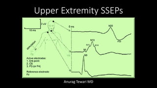
- 12. Electrode Placement • Erb’s point on each side (EP) • Over the second or fifth cervical spine process (CSp2 or CSp5) • Scalp over the contralateral cortex (CPc) and ipsilateral cortex (CPi) • Non-cephalic electrode (Ref) Anurag Tewari MD
- 13. Upper SSEPs Recording Parameters • A CONSTANT-CURRENT stimulator is the best choice for stimulation of peripheral nerves and dermatomes • because changes in the electrode impedance will not affect the current that is delivered to the nerve. • The stimulus rate should be set so that an interpretable record can be obtained in as short a time as possible • the number of responses that can be collected in a certain time increases with an increasing stimulus rate Amplitude of the response DECREASES if stimulus rate is increased above a certain value Anurag Tewari MD
- 14. Upper SSEPs Recording Parameters • In most patients, the optimal stimulus rate for • the Upper SSEP is approximately 10 pulse per second • the Lower SSEP is approximately 5 pulse per second • In patients with peripheral neuropathy, (e.g. diabetes mellitus) a lower stimulus rate yields a better response • Avoid selecting rates that are divisors of 60 Hz in North America in order to reduce contamination of the recordings with line frequency signals • Each extremity should be stimulated, one at a time Anurag Tewari MD
- 15. Upper SSEPs Recording Parameters • Number of Trials as per ACNS = 250-1000 • Number of Trials as per ASNM = 500-2000 • Analysis Time as per ACNS = 40ms • Analysis Time as per ASNM = 50ms • Stimulation Rate as per ACNS = 2-8 per second • Stimulation Rate as per ASNM = 2-5 per second Anurag Tewari MD
- 16. Upper SSEPs Recording Parameters • Pulse Width = 100-300microseconds • Stimulation Intensity = 30-40 mA • Till EP amplitude no longer increases in size • Twice motor threshold (around 6-10mA) • Impedance < 5 Kilo Ohms • for both Stimulating and Recording electrodes • Monophasic rectangular pulses Anurag Tewari MD
- 17. Upper SSEPs Recording Parameters • Bandpass as per ACNS = 30 - 1000Hz (-3dB) • Low Cut = 30Hz and • High Cut = 1000Hz (up to 3000Hz if trying to record P14) • Bandpass as per ASNM = 30 - 1000Hz (-3dB) • 30 -100Hz to 250-3000Hz for Corticals • 30-100Hz to 1000-3000Hz for Subcorticals Notch Filter OFF Anurag Tewari MD
- 18. Upper SSEPs Waveform Nomenclature • N = Negative • Peak • P = Positive • Valley • Number represents Latency • Amplitude from peak to valley • Time of slope is the duration Anurag Tewari MD
- 19. Generator Name for Upper SSEPs Montage • N9: Proximal Peripheral (Brachial Plexus) = EPi – EPc • N13: Dorsal Horn in Spinal Cord (C6) record post synaptic potential • Both Parietal and Frontal Non-Cephalic montages, referenced to contralateral shoulder (CP-Sh or Fz-Sh) record passage of ascending volleys through • Brachial Plexus (P9) • Dorsal root entry zone (P11) • Cervicomedullary junction (p14) • P14 may be composed of two peaks P13 & P14 Far Field responses are usually positive Anurag Tewari MD
- 20. Roadmap for an SSEP Anurag Tewari MD
- 21. Neural Generator for Median Nerve SSEP Label Generator Montage Used Alternate Label N9 Brachial Plexus EPi – EPc Erb’s N11 Spinal Nerve Root CSp – Fpz N13a Dorsal Horn Interneuron CSp6 – Fpz Cervical/Subcortical N13b Dorsal Column CSp2 – Fpz Cervical/Subcortical P13 Spino-medullary Junction CSp – Fpz, Mast – Fpz Cervical/Subcortical P14 Lemniscal pathway/Cuneatus Nuclei CSp – Fpz, Mast – Fpz Cervical/Subcortical N18 Brainstem/Thalamic Ci – noncephalic N19 Primary Sensory Cortex Cc – Fz, Cc – Ci N20, Cortical P22 Primary Sensory Cortex Cc – Fz, Cc – Ci Cc: C3’ or C4’, which ever is contralateral Ci: ipsilateral C3’ or C4’, which ever is ipsilateral Anurag Tewari MD
- 22. Neural Generator for Median Nerve SSEP Label Generator Montage Used Alternate Label N9 Brachial Plexus EPi – EPc Erb’s N11 Spinal Nerve Root CSp – Fpz N13a Dorsal Horn Interneuron CSp6 – Fpz Cervical/Subcortical N13b Dorsal Column CSp2 – Fpz Cervical/Subcortical P13 Spino-medullary Junction CSp – Fpz, Mast – Fpz Cervical/Subcortical P14 Lemniscal pathway/Cuneatus Nuclei CSp – Fpz, Mast – Fpz Cervical/Subcortical N18 Brainstem/Thalamic Ci – noncephalic N19 Primary Sensory Cortex Cc – Fz, Cc – Ci N20, Cortical P22 Primary Sensory Cortex Cc – Fz, Cc – Ci Cc: C3’ or C4’, which ever is contralateral Ci: ipsilateral C3’ or C4’, which ever is ipsilateral Anurag Tewari MD
- 23. Neural Generator for Median Nerve SSEP Label Generator Montage Used Alternate Label N9 Brachial Plexus EPi – EPc Erb’s N11 Spinal Nerve Root CSp – Fpz N13a Dorsal Horn Interneuron CSp6 – Fpz Cervical/Subcortical N13b Dorsal Column CSp2 – Fpz Cervical/Subcortical P13 Spinomedullary Junction CSp – Fpz, Mast – Fpz Cervical/Subcortical P14 Lemniscal pathway/Cuneatus Nuclei CSp – Fpz, Mast – Fpz Cervical/Subcortical N18 Brainstem/Thalamic Ci – noncephalic N19 Primary Sensory Cortex Cc – Fz, Cc – Ci N20, Cortical P22 Primary Sensory Cortex Cc – Fz, Cc – Ci Cc: C3’ or C4’, which ever is contralateral Ci: ipsilateral C3’ or C4’, which ever is ipsilateral Anurag Tewari MD
- 24. Neural Generator for Median Nerve SSEP Label Generator Montage Used Alternate Label N9 Brachial Plexus EPi – EPc Erb’s N11 Spinal Nerve Root CSp – Fpz N13a Dorsal Horn Interneuron CSp6 – Fpz Cervical/Subcortical N13b Dorsal Column CSp2 – Fpz Cervical/Subcortical P13 Spinomedullary Junction CSp – Fpz, Mast – Fpz Cervical/Subcortical P14 Lemniscal pathway/Cuneatus Nuclei CSp – Fpz, Mast – Fpz Cervical/Subcortical N18 Brainstem/Thalamic Ci – noncephalic N19 Primary Sensory Cortex Cc – Fz, Cc – Ci N20, Cortical P22 Primary Sensory Cortex Cc – Fz, Cc – Ci Cc: C3’ or C4’, which ever is contralateral Ci: ipsilateral C3’ or C4’, which ever is ipsilateral Anurag Tewari MD
- 25. Neural Generator for Median Nerve SSEP Label Generator Montage Used Alternate Label N9 Brachial Plexus EPi – EPc Erb’s N11 Spinal Nerve Root CSp – Fpz N13a Dorsal Horn Interneuron CSp6 – Fpz Cervical/Subcortical N13b Dorsal Column CSp2 – Fpz Cervical/Subcortical P13 Spinomedullary Junction CSp – Fpz, Mast – Fpz Cervical/Subcortical P14 Lemniscal pathway/Cuneatus Nuclei CSp – Fpz, Mast – Fpz Cervical/Subcortical N18 Brainstem/Thalamic Ci – Non-Cephalic N19 Primary Sensory Cortex Cc – Fz, Cc – Ci N20, Cortical P22 Primary Sensory Cortex Cc – Fz, Cc – Ci Cc: C3’ or C4’, which ever is contralateral Ci: ipsilateral C3’ or C4’, which ever is ipsilateral Anurag Tewari MD
- 26. Neural Generator for Median Nerve SSEP Label Generator Montage Used Alternate Label N9 Brachial Plexus EPi – EPc Erb’s N11 Spinal Nerve Root CSp – Fpz N13a Dorsal Horn Interneuron CSp6 – Fpz Cervical/Subcortical N13b Dorsal Column CSp2 – Fpz Cervical/Subcortical P13 Spinomedullary Junction CSp – Fpz, Mast – Fpz Cervical/Subcortical P14 Lemniscal pathway/Cuneatus Nuclei CSp – Fpz, Mast – Fpz Cervical/Subcortical N18 Brainstem/Thalamic Ci – noncephalic N19 Primary Sensory Cortex Cc – Fz, Cc – Ci N20, Cortical P22 Primary Sensory Cortex Cc – Fz, Cc – Ci Cc: C3’ or C4’, which ever is contralateral Ci: ipsilateral C3’ or C4’, which ever is ipsilateral Anurag Tewari MD
- 27. Neural Generator for Median Nerve SSEP Label Generator Montage Used Alternate Label N9 Brachial Plexus EPi – EPc Erb’s N13a Dorsal Horn Interneuron CSp6 – Fpz Cervical/Subcortical N13b Dorsal Column CSp2 – Fpz Cervical/Subcortical P13 Spino-medullary Junction CSp – Fpz, Mast – Fpz Cervical/Subcortical P14 Lemniscal pathway/Cuneatus Nuclei CSp – Fpz, Mast – Fpz Cervical/Subcortical N19 Primary Sensory Cortex Cc – Fz, Cc – Ci N20, Cortical Cc: C3’ or C4’, which ever is contralateral Ci: ipsilateral C3’ or C4’, which ever is ipsilateral Anurag Tewari MD
- 28. Localization of Neural Functions based on pattern of SSEP changes Locus of Neural Insult Associated Pattern of SSEP Degradation Spinal Cord Dysfunction Loss of subcortical and cortical signals, Erb’s point intact Limb Malposition Unilateral loss of Erb’s point, subcortical and cortical signals Cerebral Ischemia Unilateral cortical loss, intact subcortical signal Anesthetic effect Global cortical loss, intact subcortical signals Anurag Tewari MD
- 29. Break Questions?
- 30. Near Field vs Far Field Recording • Near Field: • Generator site of EP is close to site of recording • Placement critical • Amplitude decreases as electrode is moved away from the generator • Far Field: • Generator site of EP is far from site of recording • The “subcortical” responses (*brainstem/thalamus*) Anurag Tewari MD
- 31. Stationary vs Propagated Waves • Propagated Potential (e.g., EP or PF): • “Traveling Wave” – the action potential is “propagating” along the course of the nerve • Latency changes as you move electrode along the pathway • Little effect on amplitude as you move electrode Anurag Tewari MD
- 32. Stationary vs Propagated Waves • Stationary Potential (e.g., N13): • “Non-propagated” • “Latency is not affected by changes in the recording electrode location • Amplitude decays as you move away from source Median nerve N13 as the “stationary cervical potential”. Note amplitude change as you move away from C5, but no latency change Anurag Tewari MD
- 33. Erb’s Point (Epi-Epc) N9 • Erb's point is formed by the union of the C5 and C6 nerve roots • Located 2–3 cm above the clavicle and just lateral to the attachment of the sternocleidomastoid muscle • Stimulation at Erb’s point produces abduction of the arm and flexion of the elbow • Active electrode: Ipsilateral; 2cm superior to the midpoint of the clavicle • Recording electrode: Contralateral; 2cm superior to the midpoint of clavicle Anurag Tewari MD
- 34. Erb’s Point (Epi-Epc) N9 • Near Field recording • Waveform: Tri-Phasic (positive-negative-Positive) • Monitors Orthodromic Sensory but also has motor component • Good SNR • EP remains intact even in nerve root lesions if the cell body is intact Anurag Tewari MD
- 35. Blood Supply of Erb’s Point (Epi-Epc) N9 • Vertebral and Ascending Cervical Artery: Nerve roots • Transverse cervical, Subclavian and Axillary artery: Trunks and Cords • Subclavian and Axillary Artery: Branches of Brachial Plexus Anurag Tewari MD
- 36. N13 (CSp5-Fz) • Near Field potential • Stationary (non-propagated) • CSp5 location records the postsynaptic activity in the dorsal horn interneurons located close to the gray matter (this potential has been called N13a) Anurag Tewari MD
- 37. N13 (CSp5-Fz) • The second and fifth spinous processes are identified by counting up from the seventh, notable by its prominence at the base of the neck • CPc and CPi are scalp electrodes halfway between C3 and P3 or C4 and P4, where CPc is contralateral to the stimulus and CPi is ipsilateral to the stimulus Anurag Tewari MD
- 38. N13 (CSp5-Fz) • N13/P13 is a dorsal horn postsynaptic potential in cervical cord • Elicited by the collaterals of the primary afferent fibers in the lower cervical cord • CSp5-Fz montage records a large N13 potential that is an average of the dorsal cord potential Anurag Tewari MD
- 39. N13 (CSp5-Fz) Blood Supply = Two Posterior Spinal Arteries Anurag Tewari MD
- 40. P14 (CPi - EPc) • Far Field potential • Seen in a cephalic and non cephalic reference montage • an active cortical (usually Fz or C3/4) • non-cephalic reference (like the contralateral shoulder) • With shoulder as a reference • Recording responses near the foramen magnum • As dorsal column is becoming medial lemniscus • Wave corresponds to volley of AP at the thalamus • With Ear or Nasopharynx as a reference • The area recoded becomes rostral medial lemniscus Anurag Tewari MD
- 41. P14 (CPi - EPc) • Not recorded below the level of foramen magnum, does not reach thalamus • P14 records propagation of action potential volleys in the • Medial Lemniscus • and/or Dorsal Column • and/or Postsynaptic responses of the Cuneate Nucleus • P14 is preserved in patients with thalamic lesions • Blood supply is VERTEBROBASILAR ARTERY Anurag Tewari MD
- 42. N18 (CPi-EPc) • Obligate potential • Far Field Potential • Possible contribution from thalamus • Best recorded referentially from scalp electrodes IPSILATERAL to the stimulated nerve, away from the contralateral N20 Anurag Tewari MD
- 43. N20 (CPc-Fz) • Obligate potential • Near Field • Recorded locally over the centroparietal region contralateral to the stimulated median nerve • End of the central conduction time in upper extremity • Preserved after thalamic lesion as is thought to arise from multiple generators in brainstem Anurag Tewari MD
- 44. N20 (CPc-Fz) Blood Supply: Middle Cerebral Artery • Used as an indicator of cerebral ischemia Anurag Tewari MD
- 45. CNIM Question •Which are the Far Field Potentials in IONM Anurag Tewari MD
- 46. CNIM Question •Which are the Near Field Potentials in Upper SSEP N9 N13 N20 Anurag Tewari MD
- 47. Basis for the Use of SSEP in Monitoring Ischemia • CENTRAL CONDUCTION TIME: Interval between the P14 and the N20 peaks • CCT is used as an indicator to detect changes in the function of the central somatosensory nervous system structures • A prolongation of the CCT is taken as an indication of the beginning of ischemia Anurag Tewari MD
- 48. Basis for the Use of SSEP in Monitoring Ischemia • P14 peak is best recorded from an electrode placed at the neck area • N20 best recorded from electrode placed over the contralateral parietal scalp • The conduction time of the median nerve often increase because the arm becomes cooler during long operations—but that does not affect the CCT. Anurag Tewari MD
- 49. Some considerations • Upper limb SSEP are best recorded from electrodes placed over the contralateral parietal region of the scalp • 3–4 cm behind the central plane through C3 and C4 • 7 cm lateral from the midline (C3′ and C4′) (10–20 system) • If recorded with the active electrode placed at Cz, the N20 peak is much attenuated and the N18 peak might dominate that region of the recording • If the active electrode is placed on the ipsilateral parietal region of the scalp, the N20 peak might not be noticeable at all, and only the N18 peak would be detectable in that range of latencies • Thus, recording from different locations on the scalp makes it possible to differentiate between the N18 and N20 peaks Anurag Tewari MD
- 50. Simplified Upper Extremity SSEP Obligate Worksheet Anurag Tewari MD
- 51. Anurag Tewari MD
Editor's Notes
- Ortho: Right or Correct and Dromos means running