Role of control and instrumentation in fertilizer production plant.
use of different instruments in measurement of pressure, flow and temperature in fertilizer plant.
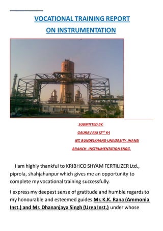
1. VOCATIONAL TRAINING REPORT
ON INSTRUMENTATION
SUBMITTED BY:
GAURAV RAI (2nd
Yr)
IET, BUNDELKHAND UNIVERSITY, JHANSI
BRANCH- INSTRUMENTATION ENGG.
I am highly thankful to KRIBHCO SHYAM FERTILIZER Ltd.,
piprola, shahjahanpur which gives me an opportunity to
complete my vocational training successfully.
I express my deepest sense of gratitude and humble regards to
my honourable and esteemed guides Mr.K.K. Rana (Ammonia
Inst.) and Mr. Dhananjaya Singh (Urea Inst.) under whose
2. regular guidance, constantsupervision and inspiring
encouragement I completed my training.
I wish to record warm regards to Mr. S.C. Nayak (H.O.D Inst.),
Mr. R.K. Shrivastav (OffsiteInst.), Mr.R.C. Shukla (Amm. Inst.),
Mr. R.K. Hooda (UreaInst.) and Mr.Tilak Dey (Inst. Workshop)
for educating us with adequate knowledge and providing
adequate facilities during training.
I extend my sincere thanks to Mr. Avinash Jha, R.K.S. Yadav, Mr.
S.N. Singh, Mr.Deepak Dutt, Mr.KamleshBhandari, Mr.
Shivanshu Pathak and Mr.Sharad Tripathi for providing me
their able guidance.
CONTENTS
1. Introduction About KSFL
2.Description of
Urea plant
Offsite plant
Ammonia plant
3. 3.Introduction to instrumentation
4.Measuring instruments
Pressure
Temperature
flow
level
5.Transmitters
6.Control valve
7.I/P signal converter
8.Distributed communication system
9.Environmental policy at KSFL
10. Conclusion
4. THE COMPANY
The Company was incorporated on December 8, 2005 pursuant
to a joint venture agreement between KRIBHCO and Shyam
Group to acquire the urea manufacturing facilities at
Shahjahanpur from Oswal Chemicals & Fertilizers Ltd. in the
share holding ratio of 60:40. Effective March 30, 2009 the
shareholding ratio of KRIBHCO and Shyam group is 85:15.
The managementcontrol of the Company rests with KRIBHCO, a
cooperative society engaged in manufacturing nitrogenous and
bio-fertilizers since 1980. KRIBHCO’s long and valuable
experience in fertilizer sector provides the Company the
advantageof their managementexpertise and business know-
how. The Company leverages on the extensive marketing and
distribution network of KRIBHCO, under which our products are
marketed. The Company also has access to ’, ‘ ’ brand,
which is a well established and respected brand amongst
farmers and co-operative societies across India.
5. UREA ...
FERTILIZERS:-Any material which supplies one or more
of the chemical elements required for the plant growth is called
a fertilizer.
Urea is an important fertilizers used by farmers for proper
growth of the crops.
PROPERTIES OF UREA
It is a white crystalline chemical.
It is saline in taste.
It is readily soluble in water.
Urea is diamine of carbonic acid.
USES OF UREA
It is used as a fertilizer and
6. It can be used as a cattle feed.
It can be used as raw material for different productslike
melamine, urea formaldehyde etc.
1.First commercial urea plant was established in GERMANY in
1920.
2.In India first urea plant was established in Sindri, Dhanbaad,
Bihar in 1959.
7. UREA PLANT
TECHNOLOGY-Snam progetti
MAIN CONSULTANT- PDIL (Projectand DevelopmentIndia Ltd.)
CAPACITY-2*1310 MTPD
No. OF UNITS- Urea plant is divided into two units namely-
1.21 UNIT- commissioned on 23rd
nov,1995
2.11 UNIT- commissioned on 14th
dec,1995
8. UREA PROCESS
RAW MATERIALS-
Ammonia(liquid) + carbon- dioxide (gaseous)
The steps involved in urea production are:-
1.Urea synthesis and high pressure recovery.
2.Urea purification and low pressure recovery.
3.Urea concentration.
4.Urea Prilling.
5.Waste water treatment.
9. UREA SYNTHESIS AND H.P. RECOVERY:- Urea is synthesised
from liquid ammonia and gaseous carbon dioxide obtained from
ammoniaplant at 17 kg/cm2
and 0.65 kg/cm2
respectively.
2NH3+CO2-> NH2COONH4 (Ammonium carbamate)
NH2COONH4-> NH2CONH2+H2O (Urea + water)
1.Compressor K-1 compresses CO2 coming from ammonia
plant at 0.65 kg/cm2
to 157 kg/cm2
pressure.
2.Ammonia is received in V-1 and its pressure is boosted by
means of pump P-5(up to 25 kg/cm2
).
3.Part of ammonia is sent to M.P. absorber C-1 & remaining is
sent to pump P-1 to a pressure of 240 kg/cm2
g.
4.In reactor R-1 ammonia and CO2 react to form ammonium
carbamate which further dehydrates to form urea and
water.
10. 5.The urea obtained here is only 33%, its concentration needs
to be increased.
6.The reaction product goes to stripper E-1, where CO2
content is reduced by the stripping action of ammonia as it
boils out of solution.
M.P. PURIFICATION AND RECOVERY
1. E-1 bottom solution which contains around 23% NH3, 5% CO2
and 45% urea is expanded to a press. Of 17 kg/cm2
and enters
the M.P. separator (MV-2) where flash gases are removed.
2. Next it goes to exchanger E-2 where most of the residual
carbamate is decomposed required heat is supplied by stem
coming from stripper.
3. NH3 and CO2 rich gases leaving the top of MV-2 are sent to
M.P. condenser (E-7) and then the mixture goes to M.P.
absorber(C-1).
4. NH3vapours leaving the top of C-1 are condensed in ammonia
condenser E-9 before entering ammonia receiver (V-1).
L.P. PURIFICATION AND RECOVERY
1. The solution which now contains 62% urea leaving the
bottom of M.P. decomposer (E-2) is expanded to a press. Of 3.5
kg/cm and enters L.P. separator/decomposer (MV-1/E-3).
2. The vapours leaving the top of separator are condensed in L.P.
decomposer E-8.
3. The solution from E-8 is sent to carbonate solution tank (V-3),
to be recycled to M.P. section by pump P-3.
11. SOLUTION CONCENTRATION AND PRILLING
1. Vaccum section is in two stages to get 99.7% melt for Prilling.
2. The 70% urea leaving the bottom of E-8 is sent to 1st
stage
Vaccum separator MV-6(operating at 0.3 ata).
3. After 1st
stage 95% urea is sent to 2nd
stage vaccum
concentrator (E-15) and separator (MV-7) working at 0.03 ata. ,
heat required is met by L.P. section.
4. Urea melt is sent to Prilling spinning bucket which distributes
the urea melts in small droplets over the cross section of natural
draught circular Prilling tower.
5. Cold air entering from bottom of the tower causes urea
droplets solidification and is discharged from the top with urea
dust.
6. Urea prills are collected at the bottom of tower and sent to
bagging plant for further activity.
PROCESS CONDENSATE TREATMENT
1.The water coming from vaccum system containing NH3
(5%),
CO2 (2%) and urea (1%) is collected in buffer waste water tank
(V-6).
2. From there it is pumped to waste water distillation tower (C2)
3. Column C-2 is divided into two parts. From the upper part
solution containing water, urea and small amount if NH3 and CO2
is to hydrolyser(R-2) where urea is decomposed into CO2 and
NH3.
12.
13. OFFSITE PLANT
The offsite plant meant to supply power to all utilities required
for production of ammonia and urea. The plant consists of
following sub plants:-
Power Generation Unit
Steam Generation Unit
D.M. Water Plant
Cooling Tower
Instrument Air Section
Effluent Treatment Plant(ETP)
Heat Recovery Steam Generator(HRSG)
Gas Turbine Generator(GTG)
Emergency Diesel Generator Set(EDG)
Ammonia Storage Unit
POWER GENERATION UNIT
The gas turbine generator is used for power generation.
The gas turbine like any other heat engine is used for
converting part of a fuel’s energy into useful available
mechanical energy.
Gas Turbine Generator (GTG):2NOS (running & 1 standby)
Manufacturer: M/S BHEL, Hyderabad
14. Capacity: 26.4MW at ISO base rating
Net Output: 20.7MW
STEAM GENERATION UNIT
Steam required for plant is supplied by SGP .The plant consists
of a gas/naptha fired service boiler and HRSG whose
specifications are as follows:-
SERVICE BOILERS
Capacity: 100 Te/Hr
Pressure: 115 kg/cm2
Temperature: 5150o
C
HRSG (Heat Recovery Steam Generator)
There are 2 HRSG, each having capacity to generate 100 MTPH
superheated steam at 515o
C and 115 kg/cm2
pressure based on
exhaust gases.
HRSG units have been supplied by M/s THERMAX BABCOCK &
WILCOX, POONA.
It consists of following arrangements in the same casing:-
Supplementary firing gas burners (8 nos.)
Super heaters
Evaporators with steam drum
Economizer also a bypass duct and a vent stack.
PERFORMANCE OF HRSG:
15. Pressure: 115 kg/cm2
at battery limit
Temperature: 515o
C at battery limit
Capacity: 100 MTPH each
Steam Quality: silica<0.02ppm & total solids<0.05ppm
D.M. PLANT
Demineralisation refers to the process of removal of all
minerals present in the raw water by using ion exchange
resin. Demineralisation uses ion exchange as the method of
purification.
Ion exchange is actually a chemical reaction in which mobile
hydrated ions of a solid are exchanged for ions of like
charge in solution. Thus the process is effective in removing
impurities and obtaining most pure boiler feed water.
DM plant consists of provision for treatment of raw water
received from tube wells and return condensate from
Ammonia and urea plants. There are different sections in
DM plant:-
i. Filteration section
ii. DM section
COOLING TOWERS
In the different sections during some processes heat is
generated which is to be removed before the product is sent for
other processes. Water is used as a cooling media for proper
and efficient operation because
It is normally plentiful.
16. It is readily available and inexpensive.
Water can carry large amount heat per unit volume and
doesn’t decompose.
During different processes cooling water gets heated up and
must be cooled before it is used again. For this process cooling
tower is used.
Cooling tower is one type of heat exchanger which cools hot
water with air i.e., by the contact b/w hot water and air, water
gets cooled.
In plant “INDUCED DRAFT CROSSED FLOW TYPE” cooling tower
is used.
INSTRUMENT AIR COMPRESSOR
Instrument air is used for operating pneumatic valves and other
processes. Three reciprocating compressors are used with
following specifications:
Capacity: 200 mm3
/hr
Pressure: 10.5 kg/cm2
(ETP) EFFLUENT TREATMENT PLANT
Different types of effluents are being generated in the plant
during different processes. These can’t be disposed of unless
the quality of effluents is within the permissible limits. Treated
sewage water is used for the irrigation of plants developed in
the surrounding for green belt.
EDG (EMERGENCY DIESEL GENERATOR)
This is a unique feature of plant, a source of power supply other
than GTG. During any failure in GTG the minimum requirement
17. for safe shutdown of the plant and GTG restart up is met by
EDG. It is 2.2 MW diesel generating power at 415 KV. Provision
has been made such that in case of power fail the engine starts
automatically and will supply power within 15-20 seconds.
AMMONIA STORAGE
As ammonia is produced in ammonia plant and consumed in
Urea plant. Sometimes it is not necessary that all ammonia
produced is consumed therefore a storage tank of 5000 MT
capacity is made to store ammonia and supply it to urea plant.
18. AMMONIA PLANT
The raw materials used for producing urea are ammonia and
carbon dioxide. These raw materials are produced in this plant.
The commercial production of ammonia is done by Haber’s
Process.
N2+3H2-> 2NH3+HEAT
Hence raw materials for ammonia are nitrogen and hydrogen.
Source of nitrogen on atmosphere and hydrogen is produced
from different fuels like:
NAPTHA
NATURAL GAS
WOOD
19. FUEL OIL
KSFL uses Natural Gas as feed stock and also as fuel in furnace.
Natural gas is supplied by GAIL via HBJ pipeline from Bombay
High.
TECHNOLOGY: Haldor Topsoe, Denmark
BASIC ENGINEERING: PDIL
DESIGN CAPACITY: 1529MTPD
The plant is divided different areas some important areas as
follows:
11 Area: NG distribution area
12 Area: Reformer section
13 Area: CO2 removal section
14 Area: Compressor section
15 Area: Ammonia refrigeration section
16 Area: Steam n/w and utility section
20. AMMONIA PROCESS
The process flow diagram of ammonia is as follows:
Following are the main process steps for the manufacturing of
ammonia:
DESULPHURISATON
In this process sulphur content is reduced to 0.05 ppm since it is
poisonous for primary reformer catalyst.
Firstly hydrogenation is done by following reaction:
H2+S->H2S
21. After hydrogenation the process gas is passed through the
absorption vessels where the H2S is absorbed on ZNO as follows:
ZnO+H2S->ZnS +H2O (Catalyst ZnO)
PRIMARY REFORMER
Here natural gas is reformed with steam to produce a mixture of
hydrogen, carbon monoxide and methane.
The steam reforming of hydrocarbons can be described by
following reactions:
CH4 + 2H2O -> 4H2 – HEAT (catalyst Ni)
CO2 + H2 -> CO + H2O – HEAT
SECONDARY REFORMER
It is to reform the primary reformer exit and to add nitrogen to
the process gas. It is done by mixing process air to the primary
reformer exit gases. Now the outlet contains H2, N2, CO, CO2 and
CH4 (0.3%).
WASTE HEAT BOILER
The temperature of secondary reformer exit is very high
(>11000
C). This temperature is used to produce H.P. steam
which is utilised as process steam and as a driving force for
major rotator equipments.
CO2 REMOVAL
GV (giammarco vetrocoke) solution is used to absorb CO2 from
the process gas thus reducing CO2 content from 17.72% to
0.05%in the gas mixture in CO2 absorber. GV solution rich in CO2
is regenerated in HP & LP regenerators by giving heat. The CO2 is
sent to urea plant.
22. METHANATION
Oxides being harmful for converter catalyst, CO and CO2 are
converted into methane.
CO + 3H2 <-> CH4 + H2O + HEAT (catalyst Ni)
CO2 + 4H2 <-> CH4 + 2H2O + HEAT
The exit synthesis gas contains mainly of hydrogen and nitrogen.
SYNTHESIS GAS COMPRESSION
The mixture is compressed to 220 kg/cm2
in synthesis gas
compressor for the synthesis of nitrogen and hydrogen.
AMMONIA SYNTHESIS
Conversion of this gas mixture into ammonia takes place in
TOPSOE-S200 radial flow converter according to the following
reaction:
3H2 + N2 <-> 2NH3 + HEAT
REFRIGERATION SYSTEM
Gas mixture containing ammonia is cooled down to separate
liquid ammonia from the gases by providing ammonia
refrigeration. Separated liquid ammonia is sent to urea plant at
120
C. In case urea plant is not in operation, product ammonia is
sent to ammonia storage.
AMMONIA RECOVERY SECTION
This section consists of an absorber operating at 14.5 kg/cm2
, a
distillation column operating at 19 kg/cm2
g. Purge gas enters to
the absorber where ammonia is absorbed in DM water. The
ammonia free gas is used as fuel in primary reformer. Ammonia
23. rich DM water is pumped to distillation column where ammonia
is stripped, condensed and sent to storage.
PURGE GAS RECVOERY
This section consists of a scrubber operating at 120 kg/cm2
,
prism separators operating at 24 kg/cm2
. Scrubber absorbs
ammonia, the ammonia free gas is fed to prism separator where
hydrogen is permeated through separator membrane and is fed
to syn gas compressor suction. Non permeated gas is used as
fuel in primary reformer.
AMMONIA CONTROL ROOM SYSTEMS
DISTRIBUTED CONTROL SYSTEM (DCS): YOKOGAWA CS3000
EMERGENCY SHUTDOWN SYSTEM (ESD): YOKOGAWA prosafe
VIBRATION MONITORING SYSTEM (VMS): BENTLY NEVADA
35000 SERIES
BURNER MANAGMENT SYSTEM (BMS)
WOODWARD GOVERNING SYSTEM
24. INSTRUMENTATION
Since the industrial processes are complicated, it is not possible
to control them without instrumentation. Thus primary
objective of instrumentation is to control plant processes
rationally and safely.
The term instrumentation refers to the design and installation
of a measuring and controlling instrument system for an
industrial process.
At the design and construction stage of the plant rationally
designed instrumentation system affects the capacities of plant
equipments and costs.
At the running stage, good instrumentation system provides
effective utilisation of raw materials ensures highest and
uniform quality of products and reduces running costs.
In addition it greatly economises manpower. It also releases
workers from routine toils. It also safeguards the plant against
hazards.
To plan an effective instrumentation system it is essential to
study in detail and consider following points:
Operating principle and capacity
Characteristics of instruments
Standard methods for start and stop of operation
25. Actions to be taken in case of strategy.
The characteristics of instruments can be divided into:
Static characteristics
2. Dynamic characteristics
STATIC CHARACTERISTICS:
These are those characteristics that must be considered when
the system or instrument is used to measure a condition that is
not varying with time. The static characteristics consist of
following:
Accuracy
Sensitivity
Reproducibility
Drift
Dead zone
DYNAMIC CHARACTERISTICS:
These characteristics are considered when measuring conditions
are varying with time.
26. MEASURING INSTRUMENTS
There are different instruments for measuring different process
parameters (pressure, temperature, flow and level). There are
instruments in field area for local indication and then
transmitting the measured signal to the control room for
controlling process.
There are four main equipments for measuring and
maintaining the process parameters:
GAUGES
TRANSMITTERS
SIWTCHES
CONTROL VALVES
PRESSURE: Pressure= Force/Area
There are different types of pressure namely:
Gauge pressure
Vaccum pressure
27. Atmospheric pressure
Absolute pressure
Different units for pressure measurement are:
Kg/cm2
mmH2O
mmHg
inH2O
inHg
psi
KPa
The relation between these units can be stated as:
1 kg/cm2
=1000 mmH2O
=14.27 psi
=98.02 KPa
=393.67 inH2O
MEASUREMENT OF PRESSURE:
Instruments used in the plant for local pressure measurement
are bourdon tubes, diaphragms gauges and bellows. Other than
this transmitter is there for transmitting pressure signal to the
control room in form of current signal (4-20 mA).
BOURDON TUBE PRESSURE GAUGE:
28. It is the most frequently used pressure gauges because of its
simplicity. There are different types of bourdon tubes used
namely:
1.C-type
2.Spiral
3.Helical etc
Construction
As the name suggests C-type bourdon tube consists of a
alphabet C shaped long thin walled cylinder made of materials
such as phosphor, bronze, steel and beryllium copper. The tube
is fixed to one end from here the pressure to be measured is
exerted, other end is free and pointer is attached to this free
end.
Operation
When pressure is applied from the fixed end, the free end
deflects due this pressure; hence the pointer attached through
suitable linkage also deflects indicating pressure on the
calibrated scale or this pressure may be transduced to an
electrical signal by one means or another.
29. DIAPHRAGM TRANSDUCER GAUGES:
A diaphragm is a thin circular sheet made mainly of rubber like
neoprene. It is clamped firmly around its edges. The diaphragms
can be in the form of flat corrugated plates and the choice
depends on the value of pressure and amount of deflection
required. There can be different types of diaphragm elements
namely:
METALLIC DIAPHRAGMS: they consist of a thin flexible
diaphragm made of metals like brass or bronze.
NON-METALLIC DIAPHRAGM: It is more difficult to measure
pressure below atmospheric pressure because changes are
Small. Hence diaphragms are made of rubbers like neoprene
etc. for the measurement of such small values of pressure.
30. The diaphragm gets deflection in accordance with the pressure
differential across the sides, deflection being towards the low
pressure side.
For low pressure or Vaccum measurement manometers,
bourdon gauges or diaphragm gauges cannot be used
effectively. For such values of pressure measurement Mc. Leod
gauge, Knudsen gauge, thermal conductivity gauge.
CAPACITIVE PRESSURE TRANSDUCER:
The principle of operation of capacitive pressure transducers is
based upon the capacitance equation of the parallel plate
capacitor.
C= (K*A)/D
Where, C, K= capacitance, dielectric constant
A,D= area of the plate, distance b/w the two plates.
TEMPERATURE: Temperature is defined as the degree of
hotness or coldness as referred to a specific scale of
temperature measurement.
31. There are different temperature scales namely:
Kelvin scale(K)
Celsius scale(0
C)
MEASUREMENT OF TEMPERATURE
There are different methods for temperature measurement.
Some of them are as follows:
BIMETALLIC TEMPERATURE GAUGES:
Construction:
Two metal strips of metal A and B having different thermal
expansion coefficient αA and αB at the same temperature are
firmly bonded together. B metal is generally made of invar,
nickel steel with a nearly zero expansion coefficient; expansion
coefficient of A is comparatively greater.
A wide range of configurations have been made for different
applications. Mainly spiral and helical are used.
Operation:
32. Since the two metal strips joined together are having different
expansion coefficient, a temperature change causes differential
expansion and the strip deflects into a circular arc and if a
pointer is attached, it will also deflect.
The accuracy of bimetallic element varies greatly depending on
the requirement of the application. The normal working range is
from -1000
to10000
F
THERMOCOUPLES
Thermocouples have been the choice of instrumentation
engineers for many years.
Construction:
Two different material wires A and B are connected to form in a
circuit with one junction at T1 temperature and other at T2. The
circuit formed is a closed one. A voltmeter can also be
connected to detect the emf produced
33. Working:
Thermocouples work on two basic principles namely Seeback
and Peltier effects.
Seeback effect states that when the two junctions are at
differential temperature, the colder junction is the reference
junction and the hotter junction is the measuring junction. Due
to this temperature difference and emf is detected in the circuit
by the voltmeter.
Peltier effect states that if one of the junctions is heated and
other is cooled and if a current is allowed to flow in the circuit,
the amount of temperature rise in one junction and the amount
of temperature fall in the other will depend on the current
intensity and direction. i.e.
Hf = πI where Hf =heat across the circuit
π = deflection coefficient
There are different types of thermocouples used namely:
J type- Iron and Constantan
34. K type- Chromel and Alumel
T type- Copper and Constantan etc.
Out of which K type is generally used with measurement range
-9000
C to 13750
C
RTD (RESISTANCE TEMPERATURE DETECTOR):
Electrical resistance of some materials changes with
temperature, such materials can be divided into two classes i.e.,
Conductors and semi conductors. The conducting materials are
called RTD and the semiconducting are known as thermistors.
The variation of resistance with temperature is given by the
relation:
R = R0 (1+a1T+a2T+........anT)
Where R0 is the resistance at temperature T=0.
They are mainly made of platinum, nickel and copper. Out of
which platinum RTDs are mostly used.
Construction:
The platinum wire usually 0.025 mm OD or less is wound into a
coil and inserted into a multicome high purity ceramic tube or
may be directly wound on the outside of a ceramic tube. The
winding is completely embedded and fused within or on the
ceramic tube utilizing extremely granular powder.
The intimate contact between the platinum winding and the
ceramic encapsulation permits rapid speed of response with the
thermal conductivity of ceramic adequate for heat transmission.
35. Following are the three RTDs:
Platinum RTDs
Thin – Film Platinum RTDs
Wire wound Platinum RTDs
Range of measurement of platinum RTDs is from -300 to 100F.
36. MEASUREMENT OF FLOW
There are numerous means of measuring the flow rate of fluids,
including liquids, slurries, gas and vapours as these materials
transit through pipelines, conduits and open channels. Due to
the differences in the properties of industrial fluids, numerous
flow measurement methods have been developed over the
years. Some flow meters determine mass directly, but the
majority of systems measure some quantitative dimensions
from which the flow rate can be inferred.
CONSTANT AREA VARIABLE PRESSURE DROP METER:
Widely used flow metering principle involves placing a fixed
area flow restriction of some type in the pipe or duct carrying
the fluid. This flow restriction causes a pressure drop by means
of a suitable differential pressure pick up allows flow rate
measurement.
Commonly used restriction element is ORIFICE. There are
different types of orifice namely:
Eccentric
Concentric
Segmental
37. Due to its simplicity and low cost it is most widely employed
flow metering element. The orifice has the largest permanent
pressure loss;
this is one of its disadvantages since it represents a power loss.
Orifice discharge coefficient is quite sensitive to the conduction
of upstream edge of the hole.
If one dimensional flow of a fluid is assumed then volume flow
rate Q1 is given as:
Q1 = {Cd A2/Г (1-(A2/A1)2
)}*{Г (2(P1-P2)/ρ}
Where A1= pipe cross section area
A2= orifice cross section area
ρ= fluid mass density
Cd= discharge coefficient
P1, P2= pressure
Other than this other flow measuring practical devices are
FLOW NOZZLE, VENTURI TUBE, DALL FLOW TUBE etc.
ROTAMETER:
38. A rotameters consists of a vertical tube with tapered bore in
which a float held in vertical position corresponding to each
flow through the tube. For a given flow rate the float remains
stationary since the vertical forces of differential pressure
Gravity, viscosity and buoyancy are balanced. This balance is self
maintaining since the meter flow area or the annular area
between the float and tube varies continuously with vertical
displacement. The tapered tube used in rotameters provides
variable area.
Fluid enters from the bottom of the tube and exerts upward
force on the float, hence the float displaces from its position.
The float position is the output of the meter.
Accuracy of rotameters is typically 2% full scale with
repeatability of about 0.25% of full scale reading.
39. MEASUREMENT OF LEVEL
Different methods are in use for level measurement and
transmission. Following are some of them:
Capacitance type
Differential pressure type
Radiation level detector
Capacitance type level detector:
The capacitor with concentric cylindrical electrodes can be used
to measure level of liquids that are non-conducting or
insulating.
The capacitance due to the columns of liquid and its vapour is
given by:
C= 2πϵ0{(ϵ1h1+ϵ2h2)/[log(r2/r1)]}
Where, ϵ1= dielectric constant of fluid
ϵ2= dielectric constant of remaining space
h1= height of fluid
h2= height of remaining space
This is the basic capacitance type level indicator:
40. A typical capacitance switch is used practically; normally the
unit attached to the tank gives the output of 4 to 20mA range
for connecting to digital microprocessor based equipment.
Diaphragm level detector:
All diaphragm detectors operate on the simple principle of
detecting the forces exerted by the process material against
diaphragm.
Differential pressure type level detector:
Liquid level can be measured by measuring a DP caused by the
weight balanced against a reference. This method of level
detection is often referred as hydrostatictank gauging especially
in the bulk liquid industries.
Differential pressure can be detected by sensing two pressures
separately and taking the difference to obtain liquid level.
The extended diaphragm version is designed to both directly to
the vessel nozzle the protrusion can be sized to fill the space in
the nozzle, placing the diaphragm flush with or slightly inside
the vessel wall.
41. This design eliminates dead end cavities and is used specially on
material that can freeze at high temperature.
Radiation level sensors:
The principle of measurement is based in irradiation method. It
utilises the physical law of absorption of radiation passing
through the matter. Resulting effect is the ratio of I and I0 i.e.
attenuated radiation and un-attenuated radiation respectively.
Radioactive source used is 60
Co as it has relatively high energy of
1.17MeV and half life of 5.27 years.
Radioactive substance is tightly welded into a stainless steel
capsule, so that it can’t leak out.
42. TRANSMITTERS
Above explained were gauges. Now the signal measured by
these gauges needs to be sent to the control room for analysing
and controlling purpose.
It consists of two functional units namely:
43. Primary unit
Secondary unit
Primary unit:
This unit includes the process interface and sensor. The process
fluid exerts pressure into the sensing unit i.e. the diaphragm. As
the measuring diaphragm deflects in response to input pressure
changes, it produces vibrations in the gap between the
magnetic disk and core of the coil mounted rigidly into primary
body. As a result the inductance of coil changes, which is
compared to that of reference inductor. The two inductance
values are combined to provide a proportionally standardsignal.
Secondary unit:
Here a microprocessor compares precisely primary output
compensating the combined effect of sensor non linearity and
temperature changes.
44. CONTROL VALVES
Control valves manipulate a flowing fluid such as gas, steam,
water or chemical component to compensate for the load
disturbance and keep the regulated process variable as close as
possible to the desired set point.
The control valve assembly typically consist of:
Valve body
Internal trim part
Actuator
Positioner
Transducer
Pressure supply
Regulator
Limit switch
45. The functional or block diagram of control valve is as follows:
Output signal from control room is sent to the I/P converter.
Output of I/P converter goes to the Positioner of the valve
where it works as signal for relay. Then according to the
percentage signal relay is operated. Air goes to the actuator
through relay where the diaphragm is displaced hence valve
opens.
46. I/P SIGNAL CONVERTER
The electro-pneumatic signal converter is used as a linking
component between electric and pneumatic system. It converts
standard electric signals (4-20mA) respectively into standard
pneumatic signal 0.2-1Bar.
Due to its innovative construction, principle based on fixed coil
and a low mass moving permanent magnet the I/P signal
47. converter is highly resistant to shocks and vibration.
Input current signal through coil armature arrangement acts on
a beam. The flapper positions itself againsta nozzle creating a
back pressure which provides feedback via a resistance orifice to
position the flapper accurately. The result is a pneumatic signal
proportional to the current.
DISTRIBUTED CONTROL SYSTEM
A DCS is a microprocessor based control and acquisition system
comprising of multiple modules over a network. The system
functions can be geographically and functionally distributed.
Operator interface to a system is through a console with CRT
display and keyboards.
48. Typical DCS are as follows:
PID CONTROL
DISCRETE CONTROL
ADVANCED CONTROL
GRAPHICALAND SCHEMATIC DISPLAY
COMMUNICATION WITH OTHER SYSTEMS AND SUB
SYSTEMS
DATA AQUISITION
REPORTGENERATION
A DCS system has following properties:
1.Measurement, control and communication are performed
by groups of modules that are distributed in function and
location.
49. 2.The control of the process by the plant operator is
performed in centralized control room.
3.Local operating control stations maybe scattered over the
plant.
4.A communication channel runs through the plant and
connects to all parts of the DCS.
5.A distributed control system can start small and expand as
need requires and circumstances permit.
6.It provides improved control of the plant by the plant
operator.
7.It provides greater flexibility to the control system with easy
changes of control plan.
In KSFL control room DCS used is of YOKOGAWA.
50. SAFETY
The plant has a highly structured housekeeping scheme, a fire
and safety department and an excellent accident-prevention
program.
Highest priority is accorded to maintain high safety standards.
Apart from holding regular fire drills, periodical emergency
mock drills are conducted onsite. Safety audits are regularly
undertaken by external experts and their recommendations are
meticulously implemented. Gas monitoring and detection
systems have been installed at toxic gas handling areas.
Approved personal protective equipment of international
standards is utilized for safe working. The Plant Safety
committee and the Central Safety committee are very active.
There is a widely publicized “Safety, Health & Environment
Policy” being diligently followed.
ENVIROMEMTAL POLICY
(ISO-14001-2004)
51. KRIBHCO SHYAM FERTILIZERS Ltd. Is committed to continually
improve its environmental performance and to prevent
pollution due to its activities associated with manufacturing and
supply of urea. Company is also committed to comply with
relevant environmental legislations and regulations.
OUR COMMITMENT SHALL BE FULLFILLED BY:
1.CONSERVATION OF NATURAL RESOURCES
2.REDUCING THE SPILLAGES AND EMISSIONS TO AIR
3.MANAGING THE WASTE GENERATED
4.MAINTAINING THE QUALITY OF TREATED EFFLUENT AND
MINIMISING THE DISCHARGE QUANTITY.
WE SHALL INVOLVE ALL EMPOLYEES IN CREATING CLEAN AND
GREEN KSFL.
52. CONCLUSION
KSFL project is one of the leading fertilizer producers in U.P.
having capacity to produce around 2600 MTPD of urea.
KSFL is environmental friendly following the norms of Uttar
Pradesh Pollution Control Board (UPCB).
The working principle is based on modern techniques which
have provision for recycling the unutilised elements and by
products.
KSFL provides an encouragement to the budding
technocrats by providing a brilliant platform to enhance
their skills.
KSFL is producing its own power which is supplied to the
township also.
IN ADDITION RECENT FOCUS IS ON THE DEVELPOMENT OF
NEEM COATED UREA.
THANK YOU