This document summarizes an intelligence digital energy meter system that uses an Arduino microcontroller to automatically monitor energy consumption and cut power if bills are unpaid. The system includes current sensors to measure load consumption, a GSM module to send alert messages to users, and relays connected to the Arduino to remotely disconnect power. It aims to reduce losses from unpaid bills by remotely disconnecting power after sending alert messages. The system could help electricity providers better monitor usage and cut down on manual disconnection of unpaid services.

![www.ijemr.net ISSN (ONLINE): 2250-0758, ISSN (PRINT): 2394-6962
41 Copyright © 2018. IJEMR. All Rights Reserved.
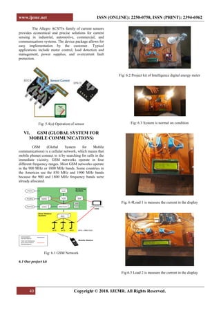
Fig:6.6 Alert message on overload through the mobile
Fig:6.7Automatic cut off power
VII. CONCLUSION
This research paper demonstrates the concept
sand implementation of automatic trip control system for
energy management using Arduino controller and GSM.
It mainly focused on industrial purpose. The similar idea
can be implemented for domestic areas for avoiding the
illegal usage of electricity. This paper is aimed at
reducing the heavy power and revenue losses that occur
due to power theft by the customers. By this design it
can be concluded that power theft can be effectively
curbed by detecting where the power theft occurs and
informing the authorities. Also, an automatic circuit
breaker may be integrated to the unit so as to remotely
cut off the power supply to the house or consumer who
tries to indulge in power theft.
FUTURESCOPE
Though many have tried implementing a
country wide AMRS, it is still an unreachable goal,
many factors like cost, feasibility and mainly the need to
replace the existing system have hindered its
development. At least in near future, the cost involved in
the building of this system could be minimized by using
more efficient technology implemented worldwide.
REFERENCES
[1] Liang Zhao. (2013). Development of an energy
monitoring system for large public buildings. Elsevier
journal, Energy and Buildings, 66, 41-48.
[2] M. Trejo-Perea, G.J. Ríos Moreno, A. Castañeda-
Miranda, D. Vargas-Vázquez, R.V. Carrillo-Serrano, &
G. Herrera-Ruiz. (2013). Development of a real time
energy monitoring platform user-friendly for buildings.
Elsevier journal Procedia Technology, 7, 238-247.
[3] Abhinandan Jain. (2012, May). Smart and Intelligent
gsm based automatic meter reading system.
International Journal of Engineering Research &
Technology,1 (3), 1-6.
[4] Abhinandan Jain. (2012, June). Design and
development of gsm based energy meter. International
Journal of Computer Applications (0975-888), 47(12),
41-45.
[5] S.H. Shete. (2013, January). GSM enabled embedded
system for energy measurement & billing. International
Journal of Scientific & Engineering Research, 4(1), 1-7.
[6] www.wikipedia.com.Traditional energy meter
systems. Available at:
https://www.google.co.in/search?q=Traditional+Energy+
meter+systems%E2%80%9D&tbm=isch&tbo=u&source
=univ&sa=X&ved=0ahUKEwi494-
rpa3bAhULMI8KHf9XB-
gQsAQIfQ&biw=1366&bih=662
[7] A. Jain, D. Kumar, & J. Kedia. (2012). Design and
development of gsm based energy meter. International
Journal of Computer applications, 47(12), 41-45.
[8] V. V. Dhok & S. S. Deshmukh. (2014). Automatic
energy meter reading system reviews. The International
Journal of science & Technoledge, 2(1), 20-24.](https://image.slidesharecdn.com/paper10-191014101016/85/Intelligence-Digital-Energy-Meter-5-320.jpg)