2
Microarchitecture of 8086/8088Microprocessor
Both the intel microprocessors, 8086 and 8088 have the
same microarchitecture;
Microarchitecture:
Provides the description of the internal architecture
about the circuit building blocks that implement
software and hardware architectures.
Implements parallel processing:
One of the main feature which enable the designer to
speed up the processing in the microcomputer;
Do you recall what were the other important features?
RAEP- SRID-UMaT, Essikado Campus
3.
3
Microarchitecture of 8086/8088Microprocessor
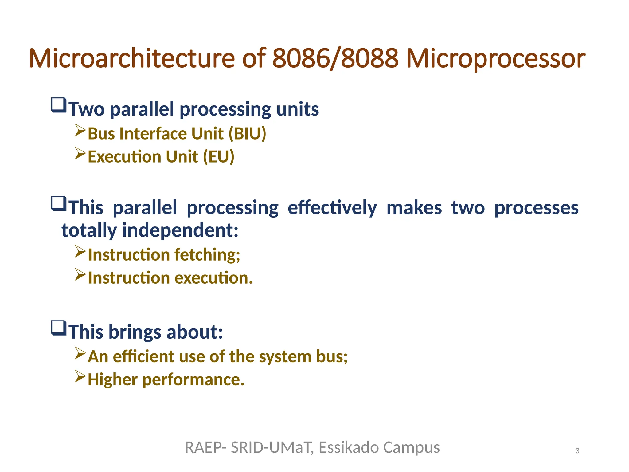
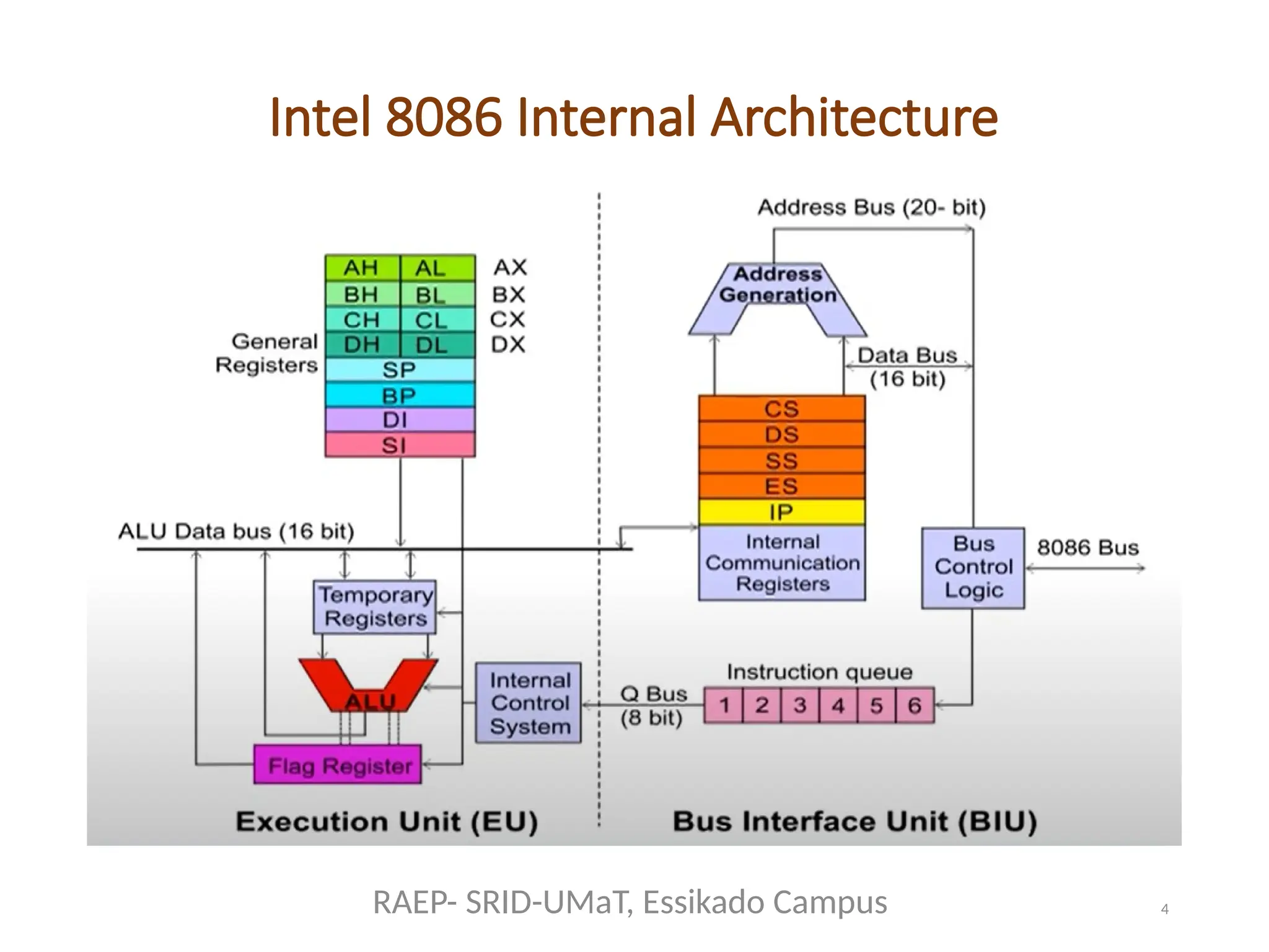
Two parallel processing units
Bus Interface Unit (BIU)
Execution Unit (EU)
This parallel processing effectively makes two processes
totally independent:
Instruction fetching;
Instruction execution.
This brings about:
An efficient use of the system bus;
Higher performance.
RAEP- SRID-UMaT, Essikado Campus
5
Bus Interface Unit(BIU)
Contains
6-bytes of Instruction Queue (4-bytes in 8088);
Segment Registers (CS, DS, ES, SS);
Instruction Pointer Register (IP);
The address Summing block;
8-bit bidirectional data bus (16-bit for 8088);
20-bit address bus;
Signals to control transactions over the bus.
RAEP- SRID-UMaT, Essikado Campus
6.
6
Functions of theBus Interface Unit (BIU)
1) Interfaces the microprocessor with external
world;
2) Responsible for performing all external bus
operations:
Instruction fetching;
Reading and writing of data operands for memory and I/O.
3) The BIU handles all transactions of data and
addresses on the buses for EU.
4) The BUI is also responsible for calculating the
addresses of the memory and I/O operands. The
instruction bytes are transferred to the
instruction queue.
RAEP- SRID-UMaT, Essikado Campus
7.
7
BIU- instruction queuing
TheBIU uses a mechanism known as an instruction stream
queue to implement a pipeline architecture.
This queue enables pre-fetching of up to 6-bytes (4-bytes in
8088) of instruction code.
This pre-fetch is done when queue has room for at least two
more bytes.
When EU is not requesting it to read or write operands
from memory, the BIU is free to look ahead in the program
memory by pre-fetching the next sequential instruction.
Pre-fetched instructions are held in the first in first out
(FIFO) queue.
If the queue is full and EU is not requesting access to data in
memory, BIU does not need to perform any bus operations.
These interval of no bus activity which occur between bus
operations are known as idle states.
RAEP- SRID-UMaT, Essikado Campus
9
Functions of theExecution Unit (EU)
1) Access instructions from the output end of
instruction queue and data from the general-
purpose memory;
2) Decodes fetched instructions;
3) Generates addresses if necessary, and
Pass them to BIU;
Requests it to perform the read and write operations
to memory or I/O.
4) Perform the operations as specified by the
instruction using control signals.
RAEP- SRID-UMaT, Essikado Campus
10.
10
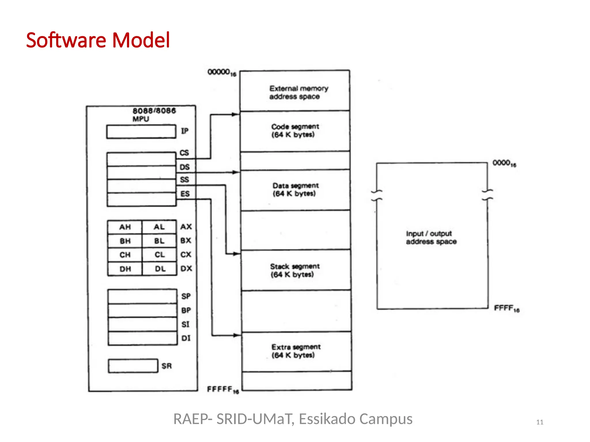
Software Model
The solepurpose of software model is to provide the
software point of view understanding of the microprocessor
to the programmer.
To successfully program the microprocessor, one needs to
know what is important and what is not needed.
What is not important to the programmer?
Function of the internal electrical circuits and
interconnections;
Hardware architecture like pin diagram is not necessarily
needed.
What is important to the programmer?
The size of external memory and internal registers;
I/O locations and how addresses of these locations are
obtained.
RAEP- SRID-UMaT, Essikado Campus
12
Software Model
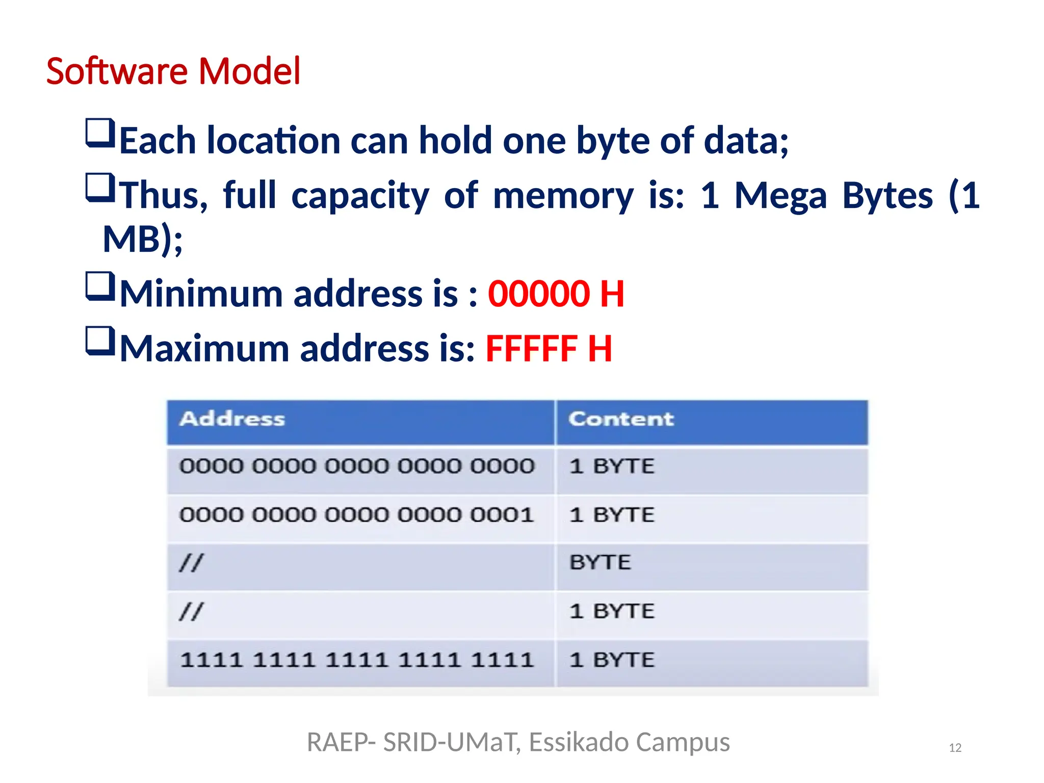
Each locationcan hold one byte of data;
Thus, full capacity of memory is: 1 Mega Bytes (1
MB);
Minimum address is : 00000 H
Maximum address is: FFFFF H
RAEP- SRID-UMaT, Essikado Campus
13.
13
Memory Organization
A bankof 1 M byte locations, each having its own unique
address (0000016 – FFFFF16).
220
= 1 MB = 1 Mega bytes of data.
Memory lies outside the processor, but it can be accessed
by it.
Memory is used to store programs instructions (code) and
data.
Intel 8086/8088 microprocessor can’t access 16 bits at a
time using data bus of 16-bit because each memory location
has 8 bits only.
These two bytes combine to form a WORD.
Uses the Little Endian approach:
Lower address byte is least significant byte
Higher address byte is most significant byte.
RAEP- SRID-UMaT, Essikado Campus
14.
14
Memory Organization
Even memoryaddress boundary:
If least significant bit of address information is 0;
Word stored at an even-address boundary corresponds to
two consecutive bytes, with LSB located at an even
address.
For example LSB is stored at 00724 H, 00000 H, 00004 H
or any multiple of 2: Aligned Words
Odd memory address boundary:
If least significant bit of address is 1;
Word stored at an odd-address boundary corresponds to two
consecutive bytes, with LSB is located at an odd address.
For example LSB is stored at 00721 H, 00001 H, 00003 H : Miss-
aligned words.
RAEP- SRID-UMaT, Essikado Campus
15.
15
Memory Organization
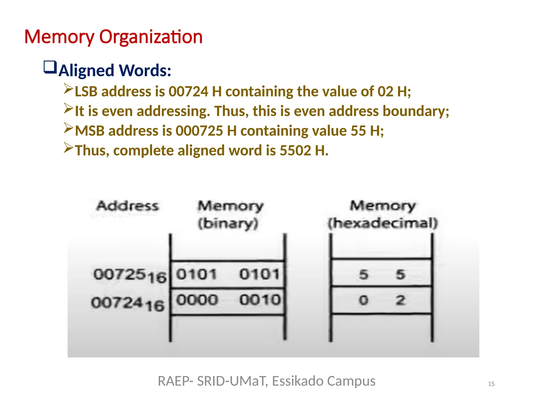
Aligned Words:
LSBaddress is 00724 H containing the value of 02 H;
It is even addressing. Thus, this is even address boundary;
MSB address is 000725 H containing value 55 H;
Thus, complete aligned word is 5502 H.
RAEP- SRID-UMaT, Essikado Campus
16.
16
Memory Organization
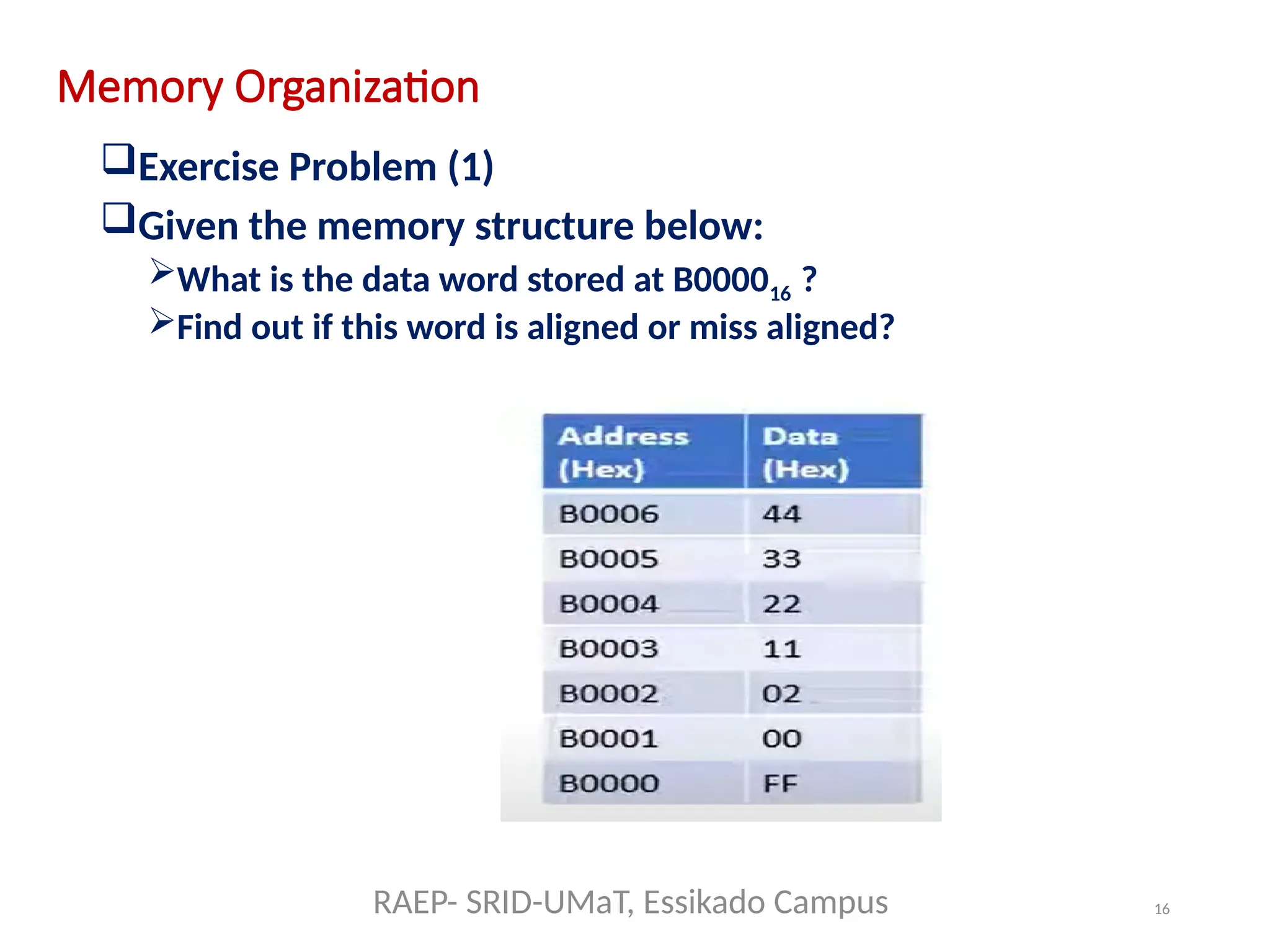
Exercise Problem(1)
Given the memory structure below:
What is the data word stored at B000016 ?
Find out if this word is aligned or miss aligned?
RAEP- SRID-UMaT, Essikado Campus
17.
17
Memory Organization
Solution toProblem (1)
LSB is stored at B0000 and MSB is stored at B0001
Data word is: 00FF H
Since it is stored at even address boundary, it will be aligned word.
RAEP- SRID-UMaT, Essikado Campus
18.
18
Memory Organization
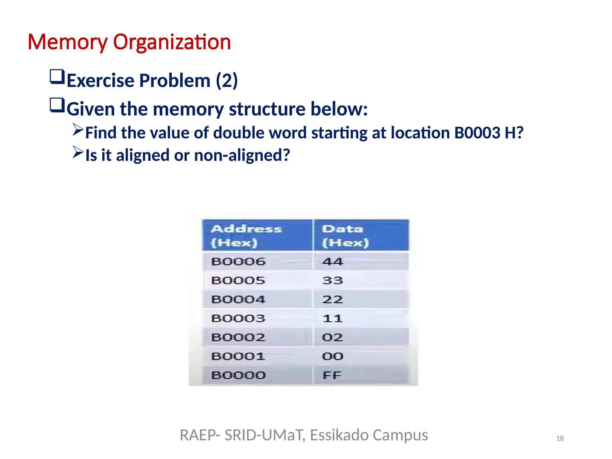
Exercise Problem(2)
Given the memory structure below:
Find the value of double word starting at location B0003 H?
Is it aligned or non-aligned?
RAEP- SRID-UMaT, Essikado Campus
19.
19
Data formats of8086/8088 Microprocessor
Byte
Word
Double Word
How these different data formats are stored in main
memory:
Little Endian.
Least Significant Byte at lower address location.
Most Significant Byte at higher address location.
RAEP- SRID-UMaT, Essikado Campus
20.
20
Data Types of8086/8088 Microprocessor
Integer Data Type
Binary Coded Decimal (BCD)
ASCII (American Standard Code for
Information Interchange)
RAEP- SRID-UMaT, Essikado Campus
21.
21
Segment Registers &Memory Segmentation
Memory segmentation is a technique used
by the 8086 microprocessor to manage its 1
MB addressable memory space efficiently.
Instead of treating memory as a single, flat
block, the 8086 divides it into segments, each
up to 64 KB in size.
RAEP- SRID-UMaT, Essikado Campus
22.
22
Segment Registers &Memory Segmentation
8086/8088 has 1 MB address space.
All this memory is not available at one time.
Memory is partitioned in segments.
Each memory segment’s size is 64 KB.
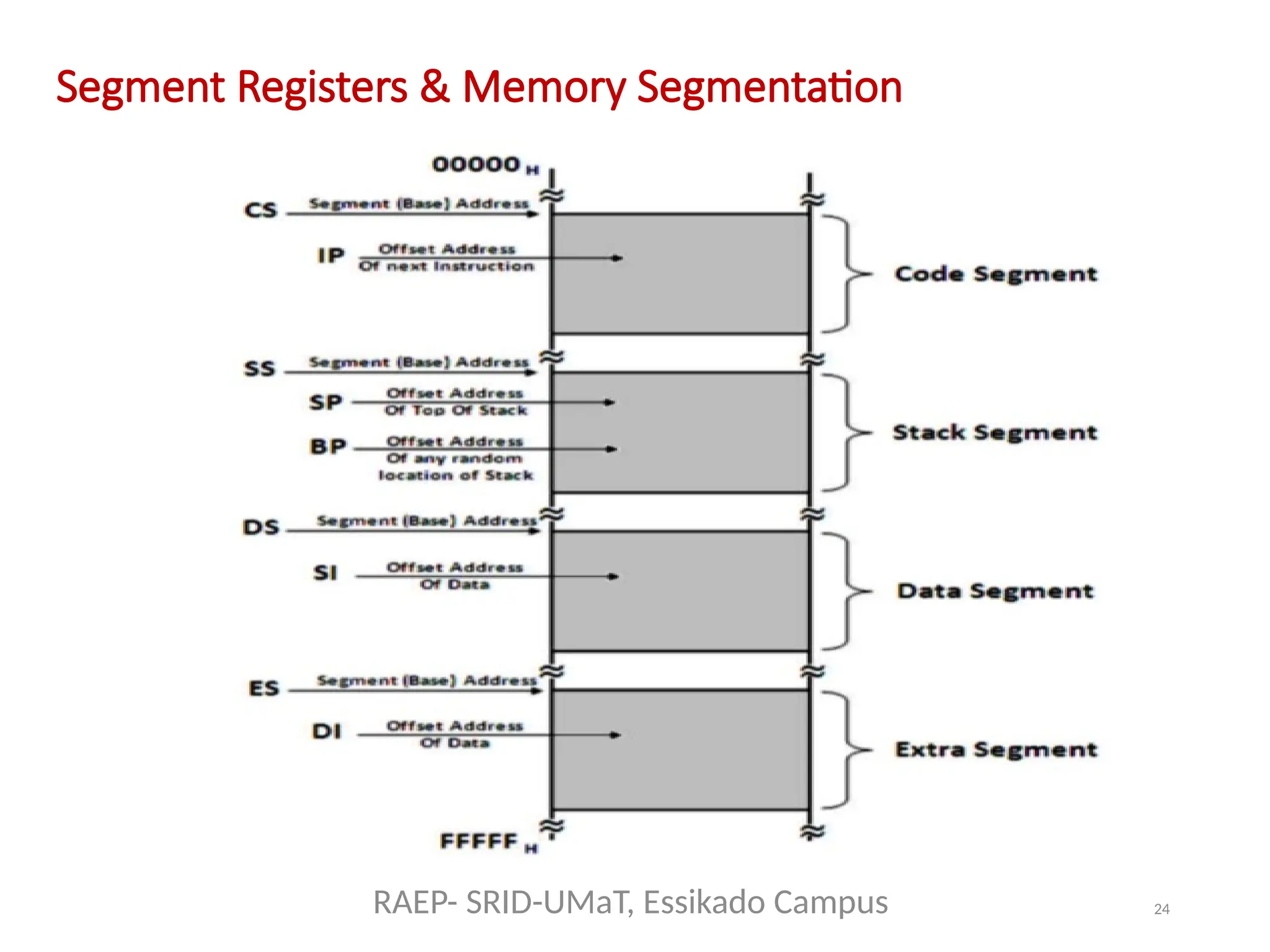
Only 4 segments are active at s time:
Code Segment
Data Segment
Stack Segment
Extra Segment
Starting address of each segment is known
as base address.
RAEP- SRID-UMaT, Essikado Campus
23.
23
Segment Registers &Memory Segmentation
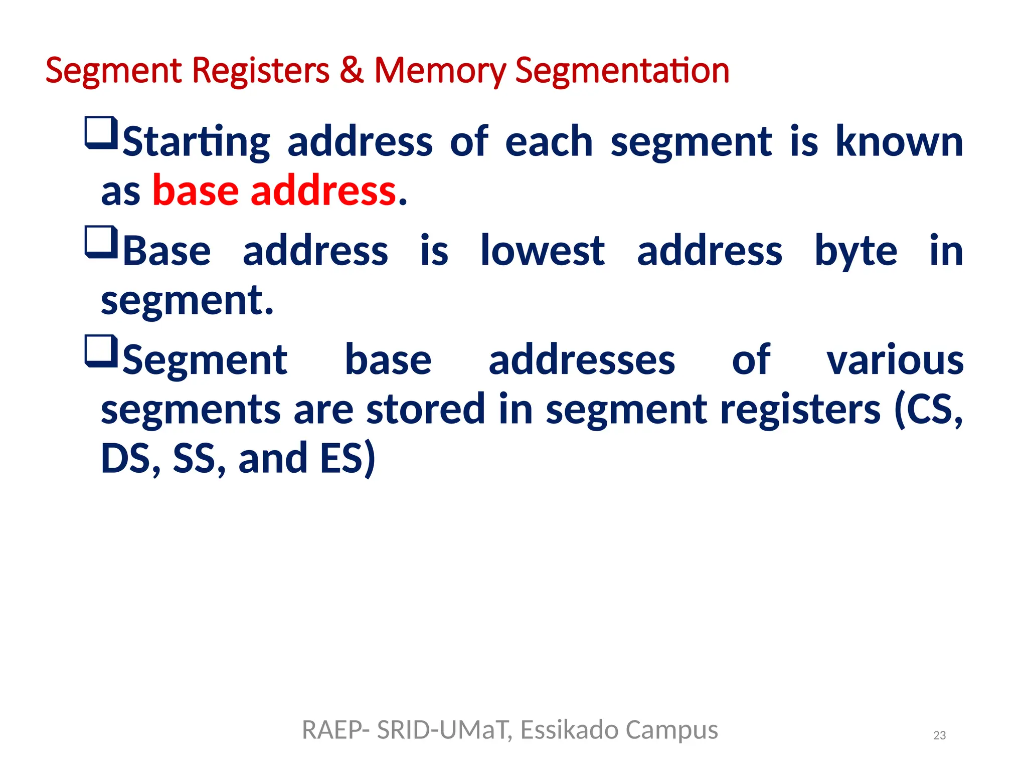
Starting address of each segment is known
as base address.
Base address is lowest address byte in
segment.
Segment base addresses of various
segments are stored in segment registers (CS,
DS, SS, and ES)
RAEP- SRID-UMaT, Essikado Campus
25
Segment Registers &Memory Segmentation
Four segments provide access to 256 KB of
active memory space:
4 X 64 KB = 256 KB
64 KB for stack memory area.
128 KB for data storage (Data + Extra
Segments).
The value of these segment registers is also
known as current-segment register values.
CS value points to the first word-wide storage
location.
Data is always fetched from memory in word
format not in byte format.
RAEP- SRID-UMaT, Essikado Campus
26.
26
Segment Registers &Memory Segmentation
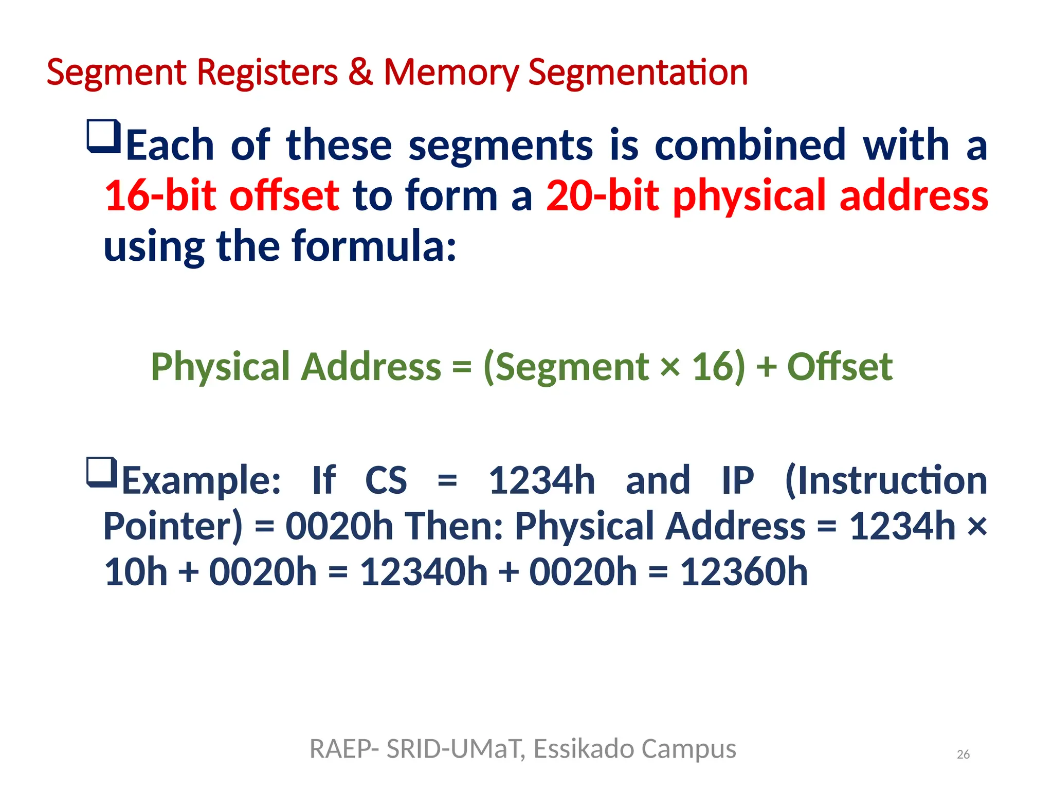
Each of these segments is combined with a
16-bit offset to form a 20-bit physical address
using the formula:
Physical Address = (Segment × 16) + Offset
Example: If CS = 1234h and IP (Instruction
Pointer) = 0020h Then: Physical Address = 1234h ×
10h + 0020h = 12340h + 0020h = 12360h
RAEP- SRID-UMaT, Essikado Campus
27.
27
Segment Registers &Memory Segmentation
Why Segmentation?
Segmented memory architecture:
1) Enables access to more memory than 16-bit
addresses allow (1 MB max).
2) Allows modular programming (code, data,
and stack are separated).
3) Improves memory organization and helps
avoid conflicts.
RAEP- SRID-UMaT, Essikado Campus
28.
28
Segment Registers &Memory Segmentation
Code Segment (CS)
Purpose: Stores the base address of executable
instructions.
Used With: Instruction Pointer (IP), which
holds the offset.
How It Works: The CPU fetches
instructions from the memory location
formed by combining CS and IP.
Example: CS = 2000h, IP = 0100h →
Instruction fetched from 20100h.
RAEP- SRID-UMaT, Essikado Campus
29.
29
Segment Registers &Memory Segmentation
Data Segment (DS)
Purpose: Points to the base address of data
(variables, arrays).
Used With: General-purpose registers like AX,
BX, CX, etc.
How It Works: Instructions like MOV AX,
[1234h] use DS by default to resolve the
physical address.
You can change DS to access different areas
of data in memory.
RAEP- SRID-UMaT, Essikado Campus
30.
30
Segment Registers &Memory Segmentation
Stack Segment (SS)
Purpose: Manages the stack—used for
function calls, returns, local variables.
Used With: Stack Pointer (SP) and Base Pointer
(BP).
How It Works: Instructions like PUSH and POP
use SS:SP to locate where to store or retrieve
values.
Stack grows downward in memory, so SP
usually decrements.
RAEP- SRID-UMaT, Essikado Campus
31.
31
Segment Registers &Memory Segmentation
Extra Segment (ES)
Purpose: Auxiliary segment, often used for
string operations and data transfer.
Used With: Registers like DI (Destination Index)
and SI (Source Index).
How It Works: Instructions like MOVSB or REP
MOVSW use ES:DI as the destination and DS:SI
as the source—critical for memory block
transfers.
RAEP- SRID-UMaT, Essikado Campus
![29
Segment Registers & Memory Segmentation
Data Segment (DS)
Purpose: Points to the base address of data
(variables, arrays).
Used With: General-purpose registers like AX,
BX, CX, etc.
How It Works: Instructions like MOV AX,
[1234h] use DS by default to resolve the
physical address.
You can change DS to access different areas
of data in memory.
RAEP- SRID-UMaT, Essikado Campus](https://image.slidesharecdn.com/intel8086-8088microprocessorassemblylanguage-250729221453-233bf39b/75/Intel-8086-8088-Microprocessor-Assembly-Language-pptx-29-2048.jpg)