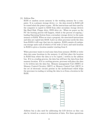
This document provides an introduction to NASM assembly language programming. It covers basics of computer organization including the processor, registers, buses, and memory. It then discusses specifics of NASM like instruction syntax, data types, and I/O. The document is intended as a reference for students learning NASM assembly programming and was updated by multiple authors under the guidance of professors at NIT Calicut.


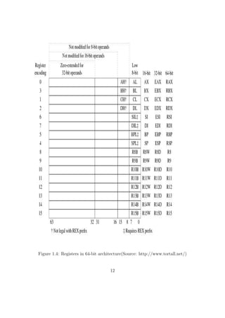
![Chapter 2
How to Start
We can classify the programming languages into three categories :
Machine Language : Machine language consists of instructions in the
form of 0's and 1's. Every CPU has its own machine language. It is
very dicult to write programs using the combination of 0's and 1's.
So we rely upon either assembly language or high level language for
writing programs.
Assembly Language : Assembly language, when compared with machine
language is in more human readable form. The general syntax of an
assembly language instruction is:
mnemonic operand(s)
Eg:
add eax, ebx
mov al, ah
inc byte[data1]
Corresponding to each assembly language instruction, there will be a
machine language instruction (ie. a hardware implementation). An
assembler converts an assembly language code into machine language.
We will be using the 'Netwide Assembler' (NASM). It is freely available
on the internet. It works for both 32bit and 64bit PCs. It can be
installed in Linux as well as Windows. Examples of other assemblers
are Microsoft Assembler (MASM) and Borland Assembler(TASM).
13](https://image.slidesharecdn.com/b9a37013-a395-452a-8662-a9aebfd637d6-141128112639-conversion-gate02/85/nasm_final-21-320.jpg)
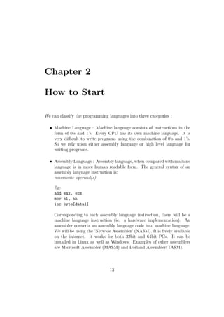
![rst converted to ASCII Code
and that numeric value will be stored in each byte location.
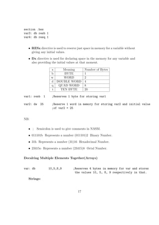
TIMES:
TIMES is used to create and initialize large arrays with a common initial value
for all its elements.
Eg:
var: times 100 db 1 ; Creates an array of 100 bytes and each element
will be initialized with the value 1
Dereferencing Mechanism in NASM:
In NASM if we have some operands in memory, we need the address of that
memory location in some variables or in any of the general purpose registers. Let
us assume that we have an address in the variable label. If we need to get the
value at that address then we need to use the dereferencing operator [ ]
Eg:
mov eax, [label] ;Value stored in the address location will be copied to eax
mov ebx, label ;The address location will be copied to ebx reg.
We need to do the type casting operations to instructions for the operands for
which the assembler wont be able to predict the number of memory locations to
be dereferenced to get the data(like INC , MOV etc). For other instructions (like
ADD, SUB etc) it is not mandatory. The directives used for specifying the data
type are: BYTE, WORD, DWORD, QWORD, TWORD.
Eg:
MOV dword[ebx], 1
INC BYTE[label]
ADD eax, dword[label]
18](https://image.slidesharecdn.com/b9a37013-a395-452a-8662-a9aebfd637d6-141128112639-conversion-gate02/85/nasm_final-35-320.jpg)
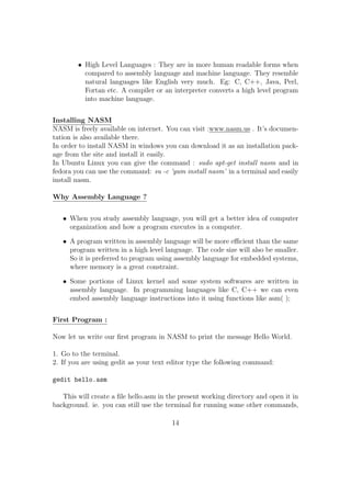
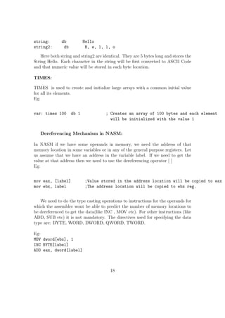
![Chapter 3
X86 - Basic Instruction Set
In this chapter we will explore the syntax of basic instructions in NASM. We will
see few examples of each instruction.
1. MOV Move/Copy
Copy the content of one register/memory to another or change the value or
a reg / memory variable to an immediate value.
sy: mov dest, src
src should be a register / memory operand
Both src and dest cannot together be memory operands.
Eg:
mov eax, ebx ;Copy the content of ebx to eax
mov ecx, 109 ;Changes the value of ecx to 109
mov al, bl
mov byte[var1], al ;Copy the content of al reg to the variable var in memory
mov word[var2], 200
mov eax, dword[var3]
2. MOVZX Move and Extend
Copy and extend a variable from a lower spaced memory / reg location to a
higher one
sy:mov src, dest
size of dest should be size of src
src should be a register / memory operand
19](https://image.slidesharecdn.com/b9a37013-a395-452a-8662-a9aebfd637d6-141128112639-conversion-gate02/85/nasm_final-36-320.jpg)
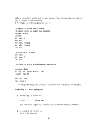
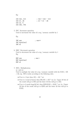
![Eg:
sub eax, ecx ; eax = eax - ecx
sub al, ah ; al = al - ah
sub ax, 5
sub edx, 31h
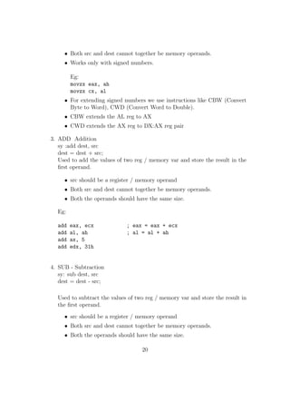
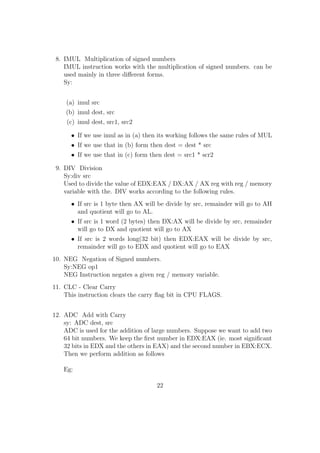
5. INC Increment operation
Used to increment the value of a reg / memory variable by 1
Eg:
INC eax ; eax++
INC byte[var]
INC al
6. DEC Decrement operation
Used to decrement the value of a reg / memory variable by 1
Eg:
DEC eax ; eax--
DEC byte[var]
DEC al
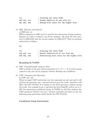
7. MUL Multiplication
sy: mul src
Used to multiply the value of a reg / memory variable with the EAX / AX
/ AL reg. MUL works according to the following rules.
If src is 1 byte then AX = AL * src
If src is 1 word (2 bytes) then DX:AX = AX * src (ie. Upper 16 bits of
the result will go to DX and the lower 16 bits will go to AX)
If src is 2 words long(32 bit) then EDX:EAX = EAX * src (ie. Upper
32 bits of the result will go to EDX and the lower 32 bits will go to
EAX)
21](https://image.slidesharecdn.com/b9a37013-a395-452a-8662-a9aebfd637d6-141128112639-conversion-gate02/85/nasm_final-40-320.jpg)
![--------
--------
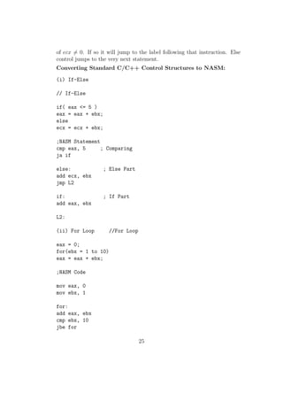
(iii) While Loop //While-Loop
sum = 0;
ecx = n;
while( ecx = 0 )
sum = sum + ecx;
;NASM Code
mov dword[sum], 0
mov ecx, dword[n]
add:
add [sum], ecx
loop add ; Decrements ecx and checks if ecx is not equal to 0 , Boolean Operators:
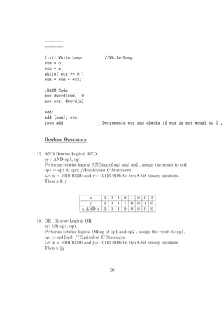
17. AND Bitwise Logical AND
sy : AND op1, op1
Performs bitwise logical ANDing of op1 and op2 , assign the result to op1.
op1 = op1 op2; //Equivalent C Statement
Let x = 1010 1001b and y= 10110 010b be two 8-bit binary numbers.
Then x y
x 1 0 1 0 1 0 0 1
y 1 0 1 1 0 0 1 0
x AND y 1 0 1 0 0 0 0 0
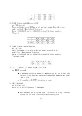
18. OR Bitwise Logical OR
sy: OR op1, op1
Performs bitwise logical ORing of op1 and op2 , assign the result to op1.
op1 = op1kop2; //Equivalent C Statement
Let x = 1010 1001b and y= 10110 010b be two 8-bit binary numbers.
Then x ky
26](https://image.slidesharecdn.com/b9a37013-a395-452a-8662-a9aebfd637d6-141128112639-conversion-gate02/85/nasm_final-50-320.jpg)
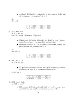
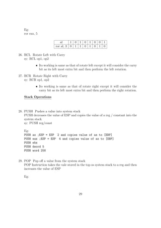
![Eg:
ror eax, 5
al 1 0 1 0 1 0 0 1
ror al, 3 0 1 1 0 1 0 1 0
26. RCL Rotate Left with Carry
sy: RCL op1, op2
Its working is same as that of rotate left except it will consider the carry
bit as its left most extra bit and then perform the left rotation.
27. RCR Rotate Right with Carry
sy: RCR op1, op2
Its working is same as that of rotate right except it will consider the
carry bit as its left most extra bit and then perform the right rotation.
Stack Operations
28. PUSH Pushes a value into system stack
PUSH decreases the value of ESP and copies the value of a reg / constant into the
system stack
sy: PUSH reg/const
Eg:
PUSH ax ;ESP = ESP 2 and copies value of ax to [EBP]
PUSH eax ;ESP = ESP 4 and copies value of ax to [EBP]
PUSH ebx
PUSH dword 5
PUSH word 258
29. POP Pop o a value from the system stack
POP Instruction takes the vale stored in the top os system stack to a reg and then
increases the value of ESP
Eg:
29](https://image.slidesharecdn.com/b9a37013-a395-452a-8662-a9aebfd637d6-141128112639-conversion-gate02/85/nasm_final-53-320.jpg)
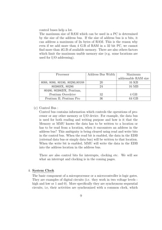
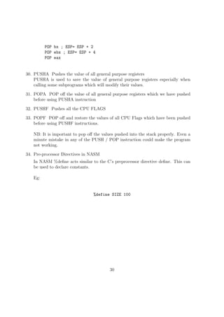
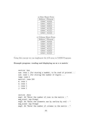
![System Call Number for Read is 3. It is copied to eax.
The standard Input device(keyboard) is having the reference num-ber
0 and it must be copied to ebx reg.
We need to copy the pointer in memory, to which we need to store
the input string to ecx reg.
We need to copy the number of characters in the string to edx reg.
Then we will trigger INT 80h.
We will get the string to the location which we copied to ecx reg.
mov eax, 3 ; Sys_call number for read
mov ebx, 0 ; Source Keyboard
mov ecx, var ; Pointer to memory location
mov edx, dword[size] ; Size of the string
int 80h ; Triggering OS Interrupt
This method is also used for reading integers and it is a bit tricky.
If we need to read a single digit, we will read it as a single character
and then subtract 30h from it(ASCII of 0 = 30h). Then we will get
the actual value of that number in that variable.
mov eax, 3
mov ebx, 0
mov ecx, digit1
mov edx, 1
int 80h
sub byte[digit1], 30h ;Now we have the actual number in [var]
Reading a two digit number:
;Reading first digit
mov eax, 3
mov ebx, 0
mov ecx, digit1
mov edx, 1
int 80h
;Reading second digit
32](https://image.slidesharecdn.com/b9a37013-a395-452a-8662-a9aebfd637d6-141128112639-conversion-gate02/85/nasm_final-59-320.jpg)
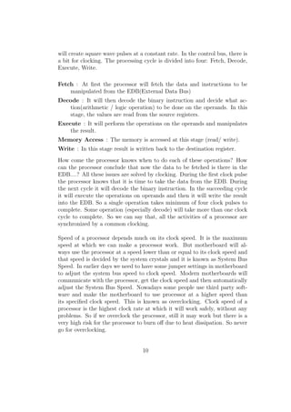
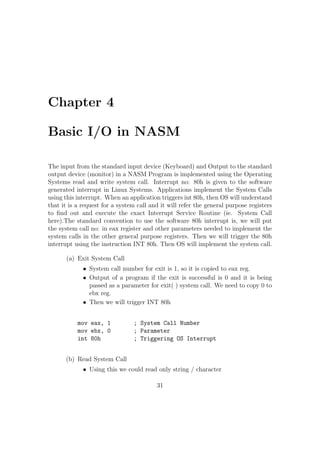
![mov eax, 3
mov ebx, 0
mov ecx, digit2
mov edx, 2 ;Here we put 2 because we need to read and
int 80h omit enter key press as well
sub byte[digit1], 30h
sub byte[digit2], 30h
;Getting the number from ASCII
; num = (10* digit1) + digit2
mov al, byte[digit1] ; Copying first digit to al
mov bl, 10
mul bl ; Multiplying al with 10
movzx bx, byte[digit2] ; Copying digit2 to bx
add ax, bx
mov byte[num], al ; We are sure that no less than 256, so we can
omit higher 8 bits of the result.
(c) Write System Call
Using this we could write only string / character
System Call Number for Write is 4. It is copied to eax.
The standard Output device(Monitor) is having the reference num-ber
1 and it must be copied to ebx reg.
We need to copy the pointer in memory, where the output sting
resides to ecx reg.
We need to copy the number of characters in the string to edx reg.
Then we will trigger INT 80h.
Eg:
mov eax, 4 ;Sys_call number
mov ebx, 1 ;Standard Output device
mov ecx, msg1 ;Pointer to output string
mov edx, size1 ;Number of characters
int 80h ;Triggering interrupt.
33](https://image.slidesharecdn.com/b9a37013-a395-452a-8662-a9aebfd637d6-141128112639-conversion-gate02/85/nasm_final-60-320.jpg)
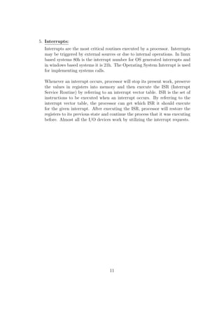
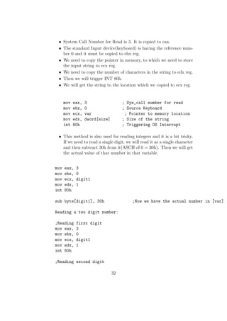
![;Calculating the number from digits
sub byte[digit1], 30h
sub byte[digit2], 30h
movzx ax, byte[digit1]
mov bl, 10
mul bl
movzx bx, byte[digit2]
add ax, bx
mov byte[num], al ; We are sure that no less than 256...
mov word[sum], 0 ; Initializing sum to zero
movzx ecx, byte[num] ; Initializing loop variable(ecx) to number
;Loop for adding ecx to num
adding:
add word[sum], cx ; Assuming maxium value in ecx will use only 16 bits
Loop adding
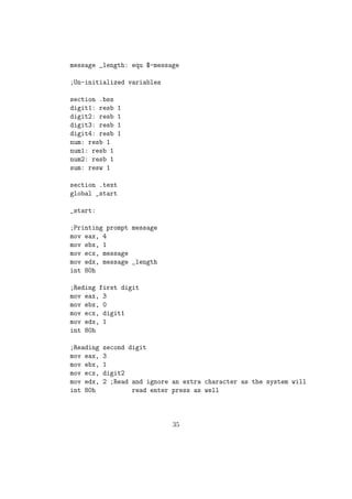
;The result could be maximum of 4 digits......
;In the remaining section of the code, we will break the
;number so as to print each digit one by one
;First splitting the number into two num1, num2 each
;having maximum 2 digits each
mov ax, word[sum]
mov bl, 100
div bl
mov byte[num1], al
mov byte[num2], ah
;Copying each digits to digit1, digit2, digit3 and digit4
movzx ax, byte[num1]
mov bl, 10
div bl
mov byte[digit4], al
mov byte[digit3], ah
36](https://image.slidesharecdn.com/b9a37013-a395-452a-8662-a9aebfd637d6-141128112639-conversion-gate02/85/nasm_final-63-320.jpg)
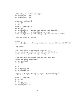
![movzx ax, byte[num2]
mov bl, 10
div bl
mov byte[digit2], al
mov byte[digit1], ah
;Converting the digit to its ASCII by adding 30h
add byte[digit1], 30h
add byte[digit2], 30h
add byte[digit3], 30h
add byte[digit4], 30h
Printing each digits.............
mov eax, 4
mov ebx, 1
mov ecx, digit4
mov edx, 1
int 80h
mov eax, 4
mov ebx, 1
mov ecx, digit3
mov edx, 1
int 80h
mov eax, 4
mov ebx, 1
mov ecx, digit2
mov edx, 1
int 80h
mov eax, 4
mov ebx, 1
mov ecx, digit1
mov edx, 1
int 80h
;Exit code
mov eax, 1
37](https://image.slidesharecdn.com/b9a37013-a395-452a-8662-a9aebfd637d6-141128112639-conversion-gate02/85/nasm_final-64-320.jpg)
![mov ebx, 0
int 80h
NB: Problem with the above code is we need to give the input as two digits. If we
need to input 9 we need to give it as 09 Output will be printed in 4 digits. ie even
if the sum is just 45 the output will be : 0045 We can correct this by reading each
digits by pushing to a stack and the popping out when new line character is being
encountered in the input. In your programs you are expected to use this method
for reading and writing numbers.
The code snippet given below gives the sample code with subprograms for reading
and printing a general 16 bit number stored in memory variable num by splitting
the number using stack. This will be the better way for inputting / outputting a
number.
section .bss
num: resw 1 ; For storing a number, to be read of printed....
nod: resb 1 ; For storing the number of digits....
temp: resb 2
section .text
global _start
_start:
call read_num
call print_num
exit:
mov eax, 1
mov ebx, 0
int 80h
;Function to read a number from console and to store that in num
read_num:
pusha
mov word[num], 0
38](https://image.slidesharecdn.com/b9a37013-a395-452a-8662-a9aebfd637d6-141128112639-conversion-gate02/85/nasm_final-65-320.jpg)
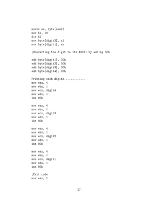
![loop_read:
mov eax, 3
mov ebx, 0
mov ecx, temp
mov edx, 1
int 80h
cmp byte[temp], 10; ASCII key for newline
je end_read
mov ax, word[num]
mov bx, 10
mul bx
mov bl, byte[temp]
sub bl, 30h
mov bh, 0
add ax, bx
mov word[num], ax
jmp loop_read
end_read:
popa
ret
;Function to print any number stored in num...
print_num:
pusha
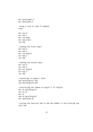
extract_no:
cmp word[num], 0
je print_no
inc byte[nod]
mov dx, 0
mov ax, word[num]
mov bx, 10
div bx
push dx
mov word[num], ax
39](https://image.slidesharecdn.com/b9a37013-a395-452a-8662-a9aebfd637d6-141128112639-conversion-gate02/85/nasm_final-66-320.jpg)
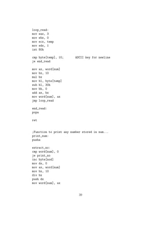
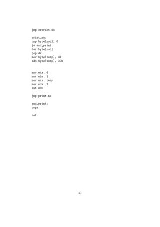
![jmp extract_no
print_no:
cmp byte[nod], 0
je end_print
dec byte[nod]
pop dx
mov byte[temp], dl
add byte[temp], 30h
mov eax, 4
mov ebx, 1
mov ecx, temp
mov edx, 1
int 80h
jmp print_no
end_print:
popa
ret
40](https://image.slidesharecdn.com/b9a37013-a395-452a-8662-a9aebfd637d6-141128112639-conversion-gate02/85/nasm_final-67-320.jpg)
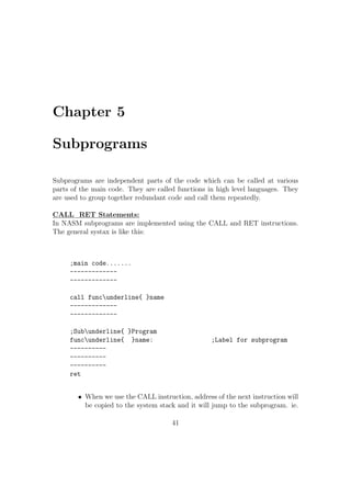
![mov byte[temp],0
mov byte[sum],0
;using a loop to read 10 numbers
read:
mov eax,4
mov ebx,1
mov ecx,msg1
mov edx,size1
int 80h
;reading the first digit
mov eax,3
mov ebx,0
mov ecx,digit1
mov edx,1
int 80h
;reading the second digit
mov eax,3
mov ebx,0
mov ecx,digit0
mov edx,2
int 80h
;converting to numeric value
sub byte[digit1],30h
sub byte[digit0],30h
;calculating the number as digit1 * 10 +digit0
mov al,byte[digit1]
mov bl,10
mul bl
add al,byte[digit0]
mov byte[num],al
;calling the function add to add the number to the existing sum
call add
43](https://image.slidesharecdn.com/b9a37013-a395-452a-8662-a9aebfd637d6-141128112639-conversion-gate02/85/nasm_final-70-320.jpg)
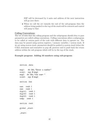
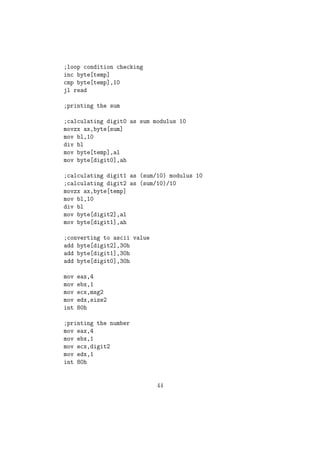
![;loop condition checking
inc byte[temp]
cmp byte[temp],10
jl read
;printing the sum
;calculating digit0 as sum modulus 10
movzx ax,byte[sum]
mov bl,10
div bl
mov byte[temp],al
mov byte[digit0],ah
;calculating digit1 as (sum/10) modulus 10
;calculating digit2 as (sum/10)/10
movzx ax,byte[temp]
mov bl,10
div bl
mov byte[digit2],al
mov byte[digit1],ah
;converting to ascii value
add byte[digit2],30h
add byte[digit1],30h
add byte[digit0],30h
mov eax,4
mov ebx,1
mov ecx,msg2
mov edx,size2
int 80h
;printing the number
mov eax,4
mov ebx,1
mov ecx,digit2
mov edx,1
int 80h
44](https://image.slidesharecdn.com/b9a37013-a395-452a-8662-a9aebfd637d6-141128112639-conversion-gate02/85/nasm_final-71-320.jpg)
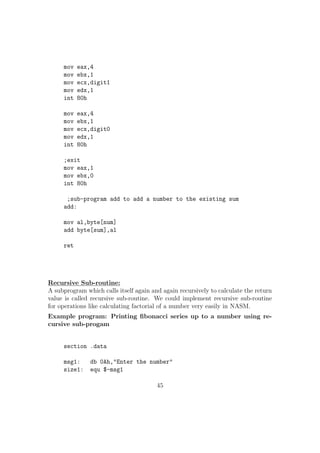
![mov eax,4
mov ebx,1
mov ecx,digit1
mov edx,1
int 80h
mov eax,4
mov ebx,1
mov ecx,digit0
mov edx,1
int 80h
;exit
mov eax,1
mov ebx,0
int 80h
;sub-program add to add a number to the existing sum
add:
mov al,byte[num]
add byte[sum],al
ret
Recursive Sub-routine:
A subprogram which calls itself again and again recursively to calculate the return
value is called recursive sub-routine. We could implement recursive sub-routine
for operations like calculating factorial of a number very easily in NASM.
Example program: Printing](https://image.slidesharecdn.com/b9a37013-a395-452a-8662-a9aebfd637d6-141128112639-conversion-gate02/85/nasm_final-72-320.jpg)
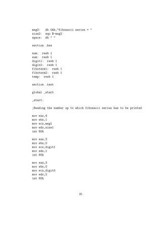
![sub byte[digit1],30h
sub byte[digit0],30h
mov al,byte[digit1]
mov bl,10
mul bl
add al,byte[digit0]
mov byte[num],al
mov byte[fiboterm1],0 ;first fibonacci term
mov byte[fiboterm2],1 ;second fibonacci term
mov eax,4
mov ebx,1
mov ecx,msg2
mov edx,size2
int 80h
;printing the first fibonacci term
movzx ax,byte[fiboterm1]
mov bl,10
div bl
mov byte[digit1],al
mov byte[digit0],ah
add byte[digit1],30h
add byte[digit0],30h
mov eax,4
mov ebx,1
mov ecx,digit1
mov edx,1
int 80h
mov eax,4
mov ebx,1
mov ecx,digit0
mov edx,1
int 80h
47](https://image.slidesharecdn.com/b9a37013-a395-452a-8662-a9aebfd637d6-141128112639-conversion-gate02/85/nasm_final-75-320.jpg)
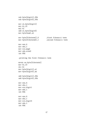
![mov eax,4
mov ebx,1
mov ecx,space
mov edx,1
int 80h
;printing the second fibonacci term
movzx ax,byte[fiboterm2]
mov bl,10
div bl
mov byte[digit1],al
mov byte[digit0],ah
add byte[digit1],30h
add byte[digit0],30h
mov eax,4
mov ebx,1
mov ecx,digit1
mov edx,1
int 80h
mov eax,4
mov ebx,1
mov ecx,digit0
mov edx,1
int 80h
mov eax,4
mov ebx,1
mov ecx,space
mov edx,1
int 80h
;calling recursive sub-program fibo to print the series
call fibo
48](https://image.slidesharecdn.com/b9a37013-a395-452a-8662-a9aebfd637d6-141128112639-conversion-gate02/85/nasm_final-76-320.jpg)
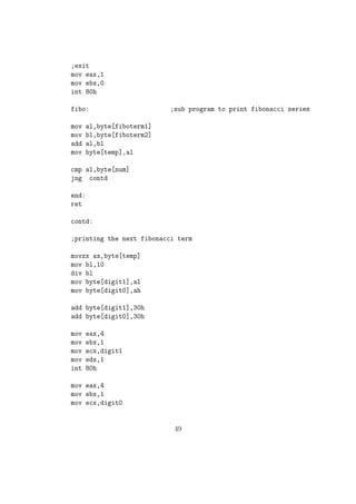
![;exit
mov eax,1
mov ebx,0
int 80h
fibo: ;sub program to print fibonacci series
mov al,byte[fiboterm1]
mov bl,byte[fiboterm2]
add al,bl
mov byte[temp],al
cmp al,byte[num]
jng contd
end:
ret
contd:
;printing the next fibonacci term
movzx ax,byte[temp]
mov bl,10
div bl
mov byte[digit1],al
mov byte[digit0],ah
add byte[digit1],30h
add byte[digit0],30h
mov eax,4
mov ebx,1
mov ecx,digit1
mov edx,1
int 80h
mov eax,4
mov ebx,1
mov ecx,digit0
49](https://image.slidesharecdn.com/b9a37013-a395-452a-8662-a9aebfd637d6-141128112639-conversion-gate02/85/nasm_final-77-320.jpg)
![mov edx,1
int 80h
mov eax,4
mov ebx,1
mov ecx,space
mov edx,1
int 80h
movzx ax,byte[fiboterm2]
mov byte[fiboterm1],al
movzx bx,byte[temp]
mov byte[fiboterm2],bl
call fibo
jmp end
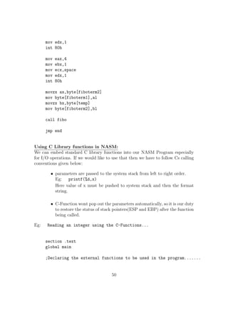
Using C Library functions in NASM:
We can embed standard C library functions into our NASM Program especially
for I/O operations. If we would like to use that then we have to follow Cs calling
conventions given below:
parameters are passed to the system stack from left to right order.
Eg: printf(%d,x)
Here value of x must be pushed to system stack and then the format
string.
C-Function wont pop out the parameters automatically, so it is our duty
to restore the status of stack pointers(ESP and EBP) after the function
being called.
Eg: Reading an integer using the C-Functions...
section .text
global main
;Declaring the external functions to be used in the program.......
50](https://image.slidesharecdn.com/b9a37013-a395-452a-8662-a9aebfd637d6-141128112639-conversion-gate02/85/nasm_final-78-320.jpg)
![extern scanf
extern printf
;Code to read an integer using the scanf function
getint:
push ebp ;Steps to store the stack pointers
mov ebp , esp
;scanf(%d,x)
;Creating a space of 2 bytes on top of stack to store the int value
sub esp , 2
lea eax , [ ebp-2]
push eax ; Pushing the address of that location
push fmt1 ; Pushing format string
call scanf ; Calling scanf function
mov ax, word [ebp-2]
mov word[num], ax
;Restoring the stack registers.
mov esp , ebp
pop ebp
ret
putint:
push ebp ; Steps to store the stack pointers
mov ebp , esp
;printf(%d,x)
sub esp , 2 ; Creating a space of 2 bytes and storing the int value mov ax, word[num]
mov word[ebp-2], ax
push fmt2 ; Pushing pointer to format string
call printf ; Calling printf( ) function
mov esp , ebp ; Restoring stack to initial values
pop ebp
ret
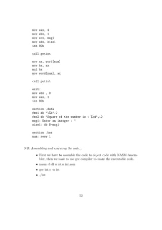
main: ; Main( ) Function
51](https://image.slidesharecdn.com/b9a37013-a395-452a-8662-a9aebfd637d6-141128112639-conversion-gate02/85/nasm_final-79-320.jpg)
![mov eax, 4
mov ebx, 1
mov ecx, msg1
mov edx, size1
int 80h
call getint
mov ax, word[num]
mov bx, ax
mul bx
mov word[num], ax
call putint
exit:
mov ebx , 0
mov eax, 1
int 80h
section .data
fmt1 db %d,0
fmt2 db Square of the number is : %d,10
msg1: Enter an integer :
size1: db $-msg1
section .bss
num: resw 1
NB: Assembling and executing the code...
First we have to assemble the code to object code with NASM Assem-bler,
then we have to use gcc compiler to make the executable code.
nasm -f elf o int.o int.asm
gcc int.o -o int
./int
52](https://image.slidesharecdn.com/b9a37013-a395-452a-8662-a9aebfd637d6-141128112639-conversion-gate02/85/nasm_final-80-320.jpg)
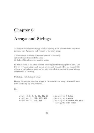
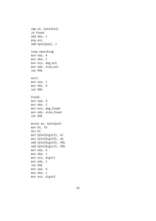
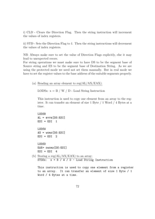
![rst element of the array.
ii) Size of each element of the array.
iii) Index of the element we want to access.
In NASM there is no array element accessing/dereferencing operator like [ ] in
C / C++ / Java using which we can access each element. Here we compute the
address of each element using an iterative control structure and traverse though
the elements of the array.
Declaring / Initializing an array:
We can declare and initialize arrays in the data section using the normal nota-tions
and listing out each elements.
Eg:
array1: db 2, 5, 8, 10, 12, 15 ; An array of 6 bytes
array2: dw 191, 122, 165, 165 ; An array of 4 words
array3: dd 111, 111, 111 ; An array of 4 dwords and each
having the same value
53](https://image.slidesharecdn.com/b9a37013-a395-452a-8662-a9aebfd637d6-141128112639-conversion-gate02/85/nasm_final-82-320.jpg)
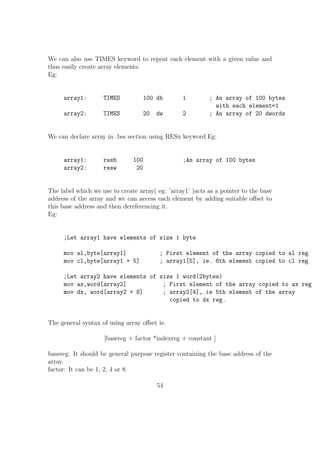
![We can also use TIMES keyword to repeat each element with a given value and
thus easily create array elements:
Eg:
array1: TIMES 100 db 1 ; An array of 100 bytes
with each element=1
array2: TIMES 20 dw 2 ; An array of 20 dwords
We can declare array in .bss section using RESx keyword.Eg:
array1: resb 100 ;An array of 100 bytes
array2: resw 20
The label which we use to create array( eg: 'array1' )acts as a pointer to the base
address of the array and we can access each element by adding suitable oset to
this base address and then dereferencing it.
Eg:
;Let array1 have elements of size 1 byte
mov al,byte[array1] ; First element of the array copied to al reg
mov cl,byte[array1 + 5] ; array1[5], ie. 6th element copied to cl reg
;Let array2 have elements of size 1 word(2bytes)
mov ax,word[array2] ; First element of the array copied to ax reg
mov dx, word[array2 + 8] ; array2[4], ie 5th element of the array
copied to dx reg.
The general syntax of using array oset is:
[basereg + factor *indexreg + constant ]
basereg: It should be general purpose register containing the base address of the
array.
factor: It can be 1, 2, 4 or 8.
54](https://image.slidesharecdn.com/b9a37013-a395-452a-8662-a9aebfd637d6-141128112639-conversion-gate02/85/nasm_final-83-320.jpg)
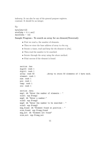
![indexreg: It can also be any of the general purpose registers.
constant: It should be an integer.
Eg:
byte[ebx+12]
word[ebp + 4 * esi]
dword[ebx - 12]
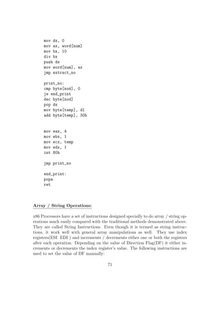
Sample Program - To search an array for an element(Traversal):
First we read n, the number of elements.
Then we store the base address of array to ebx reg.
Iterate n times, read and keep the ith element to [ebx].
Then read the number to be searched.
Iterate through the array using the above method.
Print success if the element is found.
section .bss
digit0: resb 1
digit1: resb 1
array: resb 50 ;Array to store 50 elements of 1 byte each.
element: resb 1
num: resb 1
pos: resb 1
temp: resb 1
ele: resb 1
section .data
msg1: db Enter the number of elements :
size1: equ $-msg1
msg2: db Enter a number:
size2: equ $-msg2
msg3: db Enter the number to be searched :
size3: equ $-msg3
msg_found: db Element found at position :
size_found: equ $-msg_found
msg_not: db Element not found
size_not: equ $-msg_not
55](https://image.slidesharecdn.com/b9a37013-a395-452a-8662-a9aebfd637d6-141128112639-conversion-gate02/85/nasm_final-84-320.jpg)
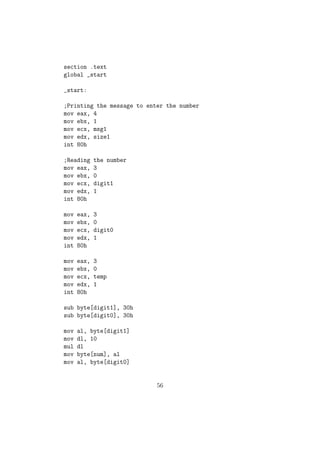
![section .text
global _start
_start:
;Printing the message to enter the number
mov eax, 4
mov ebx, 1
mov ecx, msg1
mov edx, size1
int 80h
;Reading the number
mov eax, 3
mov ebx, 0
mov ecx, digit1
mov edx, 1
int 80h
mov eax, 3
mov ebx, 0
mov ecx, digit0
mov edx, 1
int 80h
mov eax, 3
mov ebx, 0
mov ecx, temp
mov edx, 1
int 80h
sub byte[digit1], 30h
sub byte[digit0], 30h
mov al, byte[digit1]
mov dl, 10
mul dl
mov byte[num], al
mov al, byte[digit0]
56](https://image.slidesharecdn.com/b9a37013-a395-452a-8662-a9aebfd637d6-141128112639-conversion-gate02/85/nasm_final-85-320.jpg)
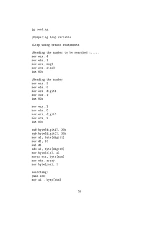
![add byte[num], al
mov al, byte[num]
mov byte[temp], al
mov ebx, array
reading:
push ebx ;Preserving The value of ebx in stack
;Printing the message to enter each element
mov eax, 4
mov ebx, 1
mov ecx, msg2
mov edx, size2
int 80h
;Reading the number
mov eax, 3
mov ebx, 0
mov ecx, digit1
mov edx, 1
int 80h
mov eax, 3
mov ebx, 0
mov ecx, digit0
mov edx, 2
int 80h
sub byte[digit1], 30h
sub byte[digit0], 30h
mov al, byte[digit1]
mov dl, 10
mul dl
add al, byte[digit0]
;al now contains the number
pop ebx
mov byte[ebx], al
add ebx, 1
dec byte[temp]
57](https://image.slidesharecdn.com/b9a37013-a395-452a-8662-a9aebfd637d6-141128112639-conversion-gate02/85/nasm_final-86-320.jpg)
![cmp byte[temp], 0
jg reading
;Comparing loop variable
;Loop using branch statements
;Reading the number to be searched :.....
mov eax, 4
mov ebx, 1
mov ecx, msg3
mov edx, size3
int 80h
;Reading the number
mov eax, 3
mov ebx, 0
mov ecx, digit1
mov edx, 1
int 80h
mov eax, 3
mov ebx, 0
mov ecx, digit0
mov edx, 2
int 80h
sub byte[digit1], 30h
sub byte[digit0], 30h
mov al, byte[digit1]
mov dl, 10
mul dl
add al, byte[digit0]
;al now contains the number
pop ebx
mov byte[ebx], al
add ebx, 1
dec byte[temp]
cmp byte[temp], 0
58](https://image.slidesharecdn.com/b9a37013-a395-452a-8662-a9aebfd637d6-141128112639-conversion-gate02/85/nasm_final-87-320.jpg)
![jg reading
;Comparing loop variable
;Loop using branch statements
;Reading the number to be searched :.....
mov eax, 4
mov ebx, 1
mov ecx, msg3
mov edx, size3
int 80h
;Reading the number
mov eax, 3
mov ebx, 0
mov ecx, digit1
mov edx, 1
int 80h
mov eax, 3
mov ebx, 0
mov ecx, digit0
mov edx, 2
int 80h
sub byte[digit1], 30h
sub byte[digit0], 30h
mov al, byte[digit1]
mov dl, 10
mul dl
add al, byte[digit0]
mov byte[ele], al
movzx ecx, byte[num]
mov ebx, array
mov byte[pos], 1
searching:
push ecx
mov al , byte[ebx]
59](https://image.slidesharecdn.com/b9a37013-a395-452a-8662-a9aebfd637d6-141128112639-conversion-gate02/85/nasm_final-88-320.jpg)


