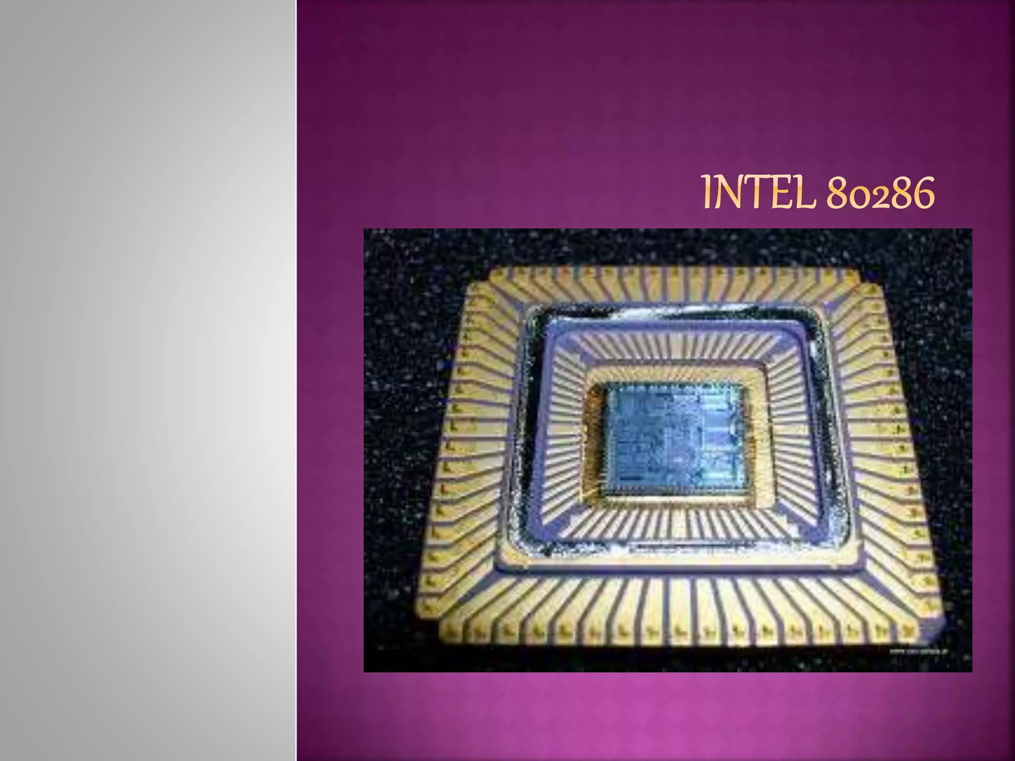
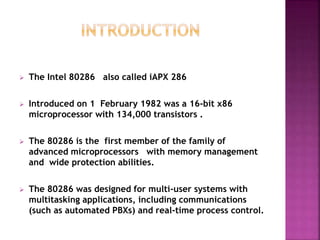
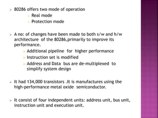
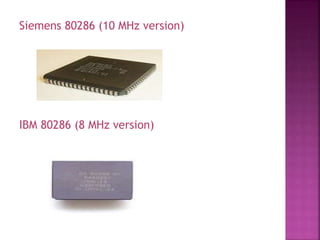
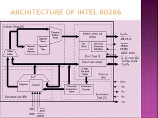
80286 is the first member of the family of advanced microprocessors with memory management and wide protection abilities.This designed for multi-user systems with multitasking applications
2. The Intel 80286 also called iAPX 286
Introduced on 1 February 1982 was a 16-bit x86
microprocessor with 134,000 transistors .
The 80286 is the first member of the family of
advanced microprocessors with memory management
and wide protection abilities.
The 80286 was designed for multi-user systems with
multitasking applications, including communications
(such as automated PBXs) and real-time process control.
3. 80286 offers two mode of operation
Real mode
Protection mode
A no: of changes have been made to both s/w and h/w
architecture of the 80286,primarily to improve its
performance.
Additional pipeline for higher performance
Instruction set is modified
Address and Data bus are de-multiplexed to
simplify system design
It had 134,000 transistors .It is manufactures using the
high-performance metal oxide semiconductor.
It consist of four independent units: address unit, bus unit,
instruction unit and execution unit.
6. Internal Architecture
The 80286 is internally partitioned into four
Bus Unit
Instruction Unit
Execution Unit
Address Unit
Bus Unit
The bus unit interface with the outside world . It provide
a 16 bit data bus, 24 bit address bus and the signals
needed to control bus transfers buses are de-multiplexed.
Bus unit is responsible for performing all external bus
operation.
Processing unit contain the latches and drives for address
bus and transceivers for the data buses.
7. Bus unit also contains element called the pre-fetcher and
prefetch queue..together these elements implement a
mechanism know as an instruction stream queue.
Address Unit
Address unit is provides the memory management and
protection services for the 80286.
It off-load the responsibility for performing high speed
address calculation ,virtual to physical transition and limit
and access right attributes checks.
Address unit calculate the next instruction to be fetched.
Address unit perform more function ,it perform the various
address transaction and protection checks needed when
performing protected mode bus cycle.
8. Instruction Unit
The IU access the output end of the prefetch queue. It
read one instruction byte after the other from the output
of the queue and decode them into the 69-bit instruction
format used by the 80286 EU.
IU off-load the responsibility for instruction decoding from
the execution unit.
Instruction queue within the instruction unit permit three
fully decoded instruction to be waiting for execution by
the execution unit.
Execution Unit
EU include the ALU and a control ROM .Block labeled
registers represents all the uses –accessible registers.
Control Rom contain the microcode sequences that define
the operation performed by the 80286’s instruction.
EU read decoded instructions from the instruction queue
and perform the operations that they specify.
9. CLTS Clear the task-switched flag bit
LAR Load access rights
LSL Load segment limit
ARPL Adjust requested privilege level
VERR Verify for read access
VERW Verify for write access
LDGT Load the global descriptor table register
SGDT Store the global descriptor table register
LIDT Load the interrupt descriptor table register
SIDT Store the interrupt descriptor table register
LMSW Load the machine status word
SMSW Store the machine status word
SAR Store the access right
LLDT Load the local descriptor table register
SLDT Store the local descriptor table register
12. 80286 have two modes of operations
Real mode
Protected mode or soft ware
Real mode
Real mode is a normal mode or 80286 is power on it comes
up in the real mode.
When in the real mode , the 80286 can be used to execute
the base instruction set of the 8086.
The code for the base instruction of the 80286 is identical
to that of the 8086.
No: of new instruction have been added in the instruction
set of the 80286 to enhance performance and function .
A new register called the machine status word register
(MSW).This is used to switch the 80286 from real mode to
protected mode.
Memory Addressing in 80286
13. Address is 20 bit with 16 bit segment and 16 bit offset. When
80286 is hardware reset, it automatically enters real address
mode.
Protected mode
1 Gbyte of virtual memory and 16 Mbyte of physical
memory. The address is 24 bit. To enter PVAM mode,
Processor Status Word (PSW) is loaded by the instruction
LPSW.
In Protected virtual address mode (PVAM) the 80286 has its
multitasking capability.
The 80286 PVAM extends use of segments in such a way
that the segment of several tasks can reside in memory at
the same time and can by dynamically loaded as the need
arises.
In order to provide protection between segments with in a
task , segments are assigned to one of four privileged
levels. Thus the various tasks and segment are protected
form unwanted access by type segment ,level and task
protection mechanism.
15. code segment
Stack segment
Data segment
Level 0-Most privileged
Level 1
Level 2
Level 3-Least Privileged
Level 0 would normally include only the very critical
modules in the operating system.
Level 1 modules would consist chiefly of the less critical
operating system services.
Level 3 would be for application program and Level 2 most
often would be used for custom extension to these
programs.
1
2
3
4
16. Multi Tasking
In 80286 we improve the multitasking capability by adding
necessary memory management and task switching in such
way that there is adequate protection
Between the application task and the system and other
more privileged task
For separating the from each other
Between the code and data module
Again unwanted accessing or changing the data or code.
The primary key to multi-tasking in the ability to break the
various entities to be processed into part in such a way that
the part can easily function together and adequate
protection is maintained .
Modularity is important in that it allow the programmer to
view the entire system as collection of modules that make up
the task and subtask.so that operating system module that
include critical code and data table can be protected from
application program.
17. Second key to multi tasking is the ability to change quickly
and smoothly from one task to another.
The task containing the module that is currently executing
is called current task.
As the time progresses ,it is necessary to change the
current task ie:- to set aside logically the segments that
comprise the current task and make the segment in
another task the current task . This is called
task switching.