Approaches plates and approach charts explanations
The document provides detailed information on instrument approach procedures (IAPs), including the segmentation of IAPs into initial, intermediate, final, and missed approach segments. It outlines the distinctions between precision and non-precision approaches and explains the requirements for each, as well as the procedures for approach clearance, straight-in landings, and missed approach protocols. Additionally, it emphasizes the importance of reviewing charts and understanding landing minimums, communication procedures, and the role of various navigational aids in the approach process.
Approaches plates and approach charts explanations
1.
Approach Charts andProcedures
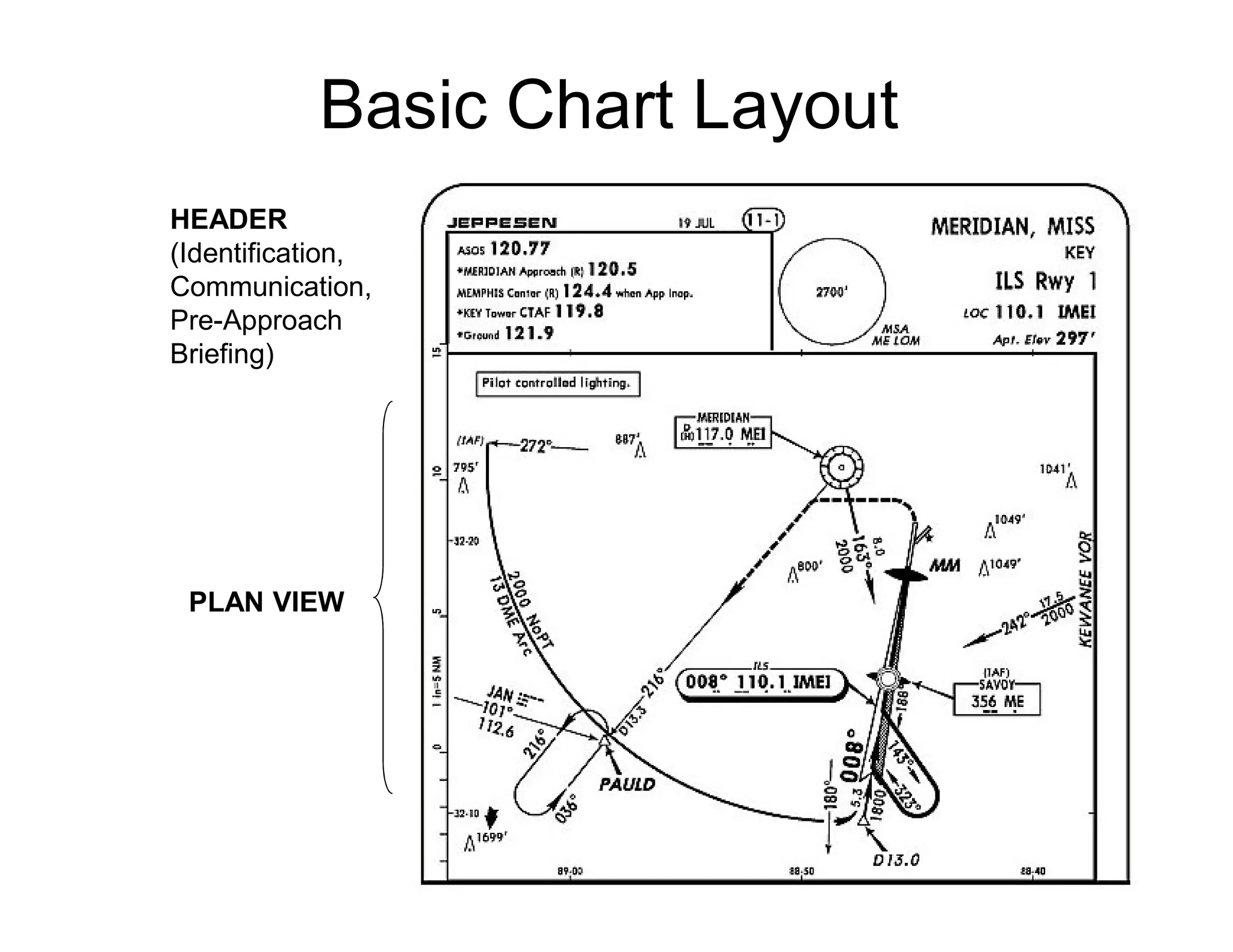
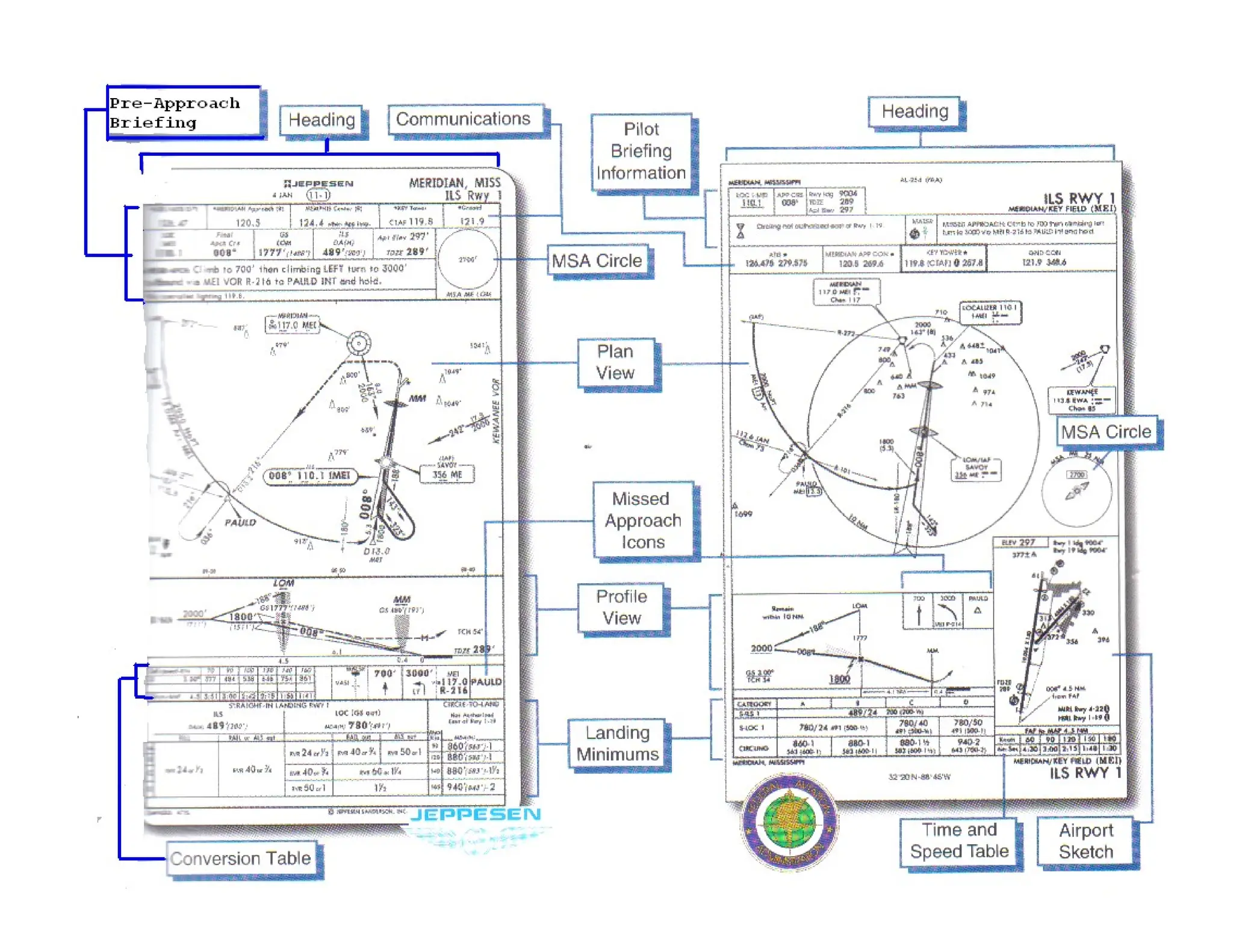
• Key Features
• Heading, Briefing, and Communications
Information
• Plan View and Minimum Safe Altitude
• Profile and Missed Approach Icons
• Time and Speed Table
• Landing Minimums
• Airport Sketch and Airport Diagram
• Alternate Airports
2.
Instrument Approach Procedures(IAPs)
An instrument approach procedure…
– allows you to descend safely
– by reference to instruments
– from the en route structure
– to a point where a safe landing can be made
There are 2 general types of IAPs
– Precision approaches, e.g., ILS, PAR
• provide vertical, as well as course, guidance
– Nonprecision approaches, e.g, VOR, NDB,
ASR
• provide only course guidance
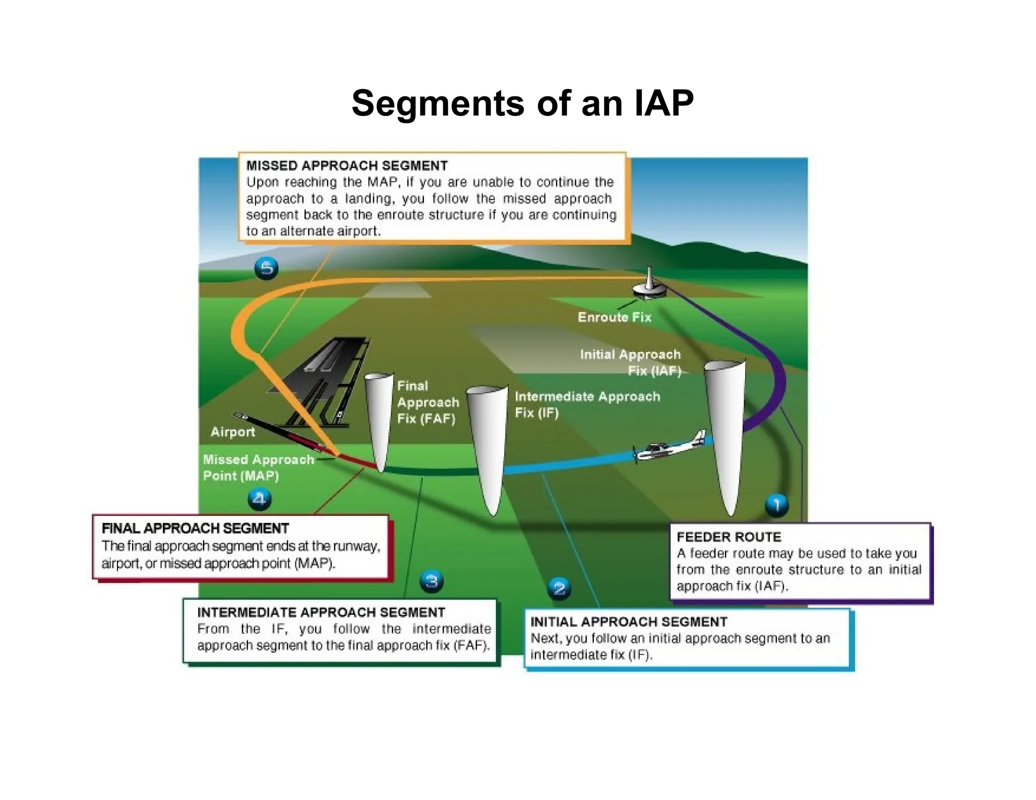
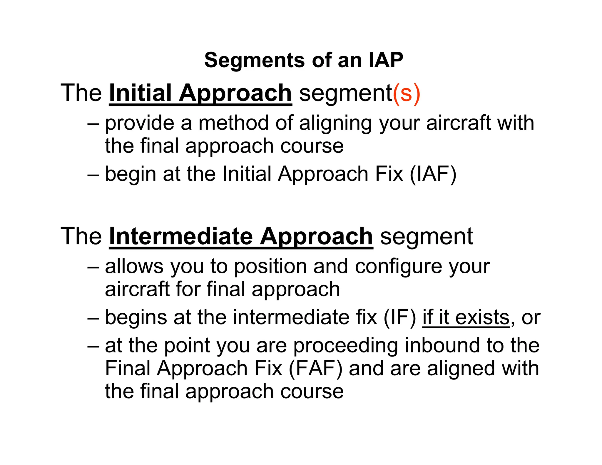
Segments of anIAP
The Initial Approach segment(s)
– provide a method of aligning your aircraft with
the final approach course
– begin at the Initial Approach Fix (IAF)
The Intermediate Approach segment
– allows you to position and configure your
aircraft for final approach
– begins at the intermediate fix (IF) if it exists, or
– at the point you are proceeding inbound to the
Final Approach Fix (FAF) and are aligned with
the final approach course
5.
Segments of anIAP
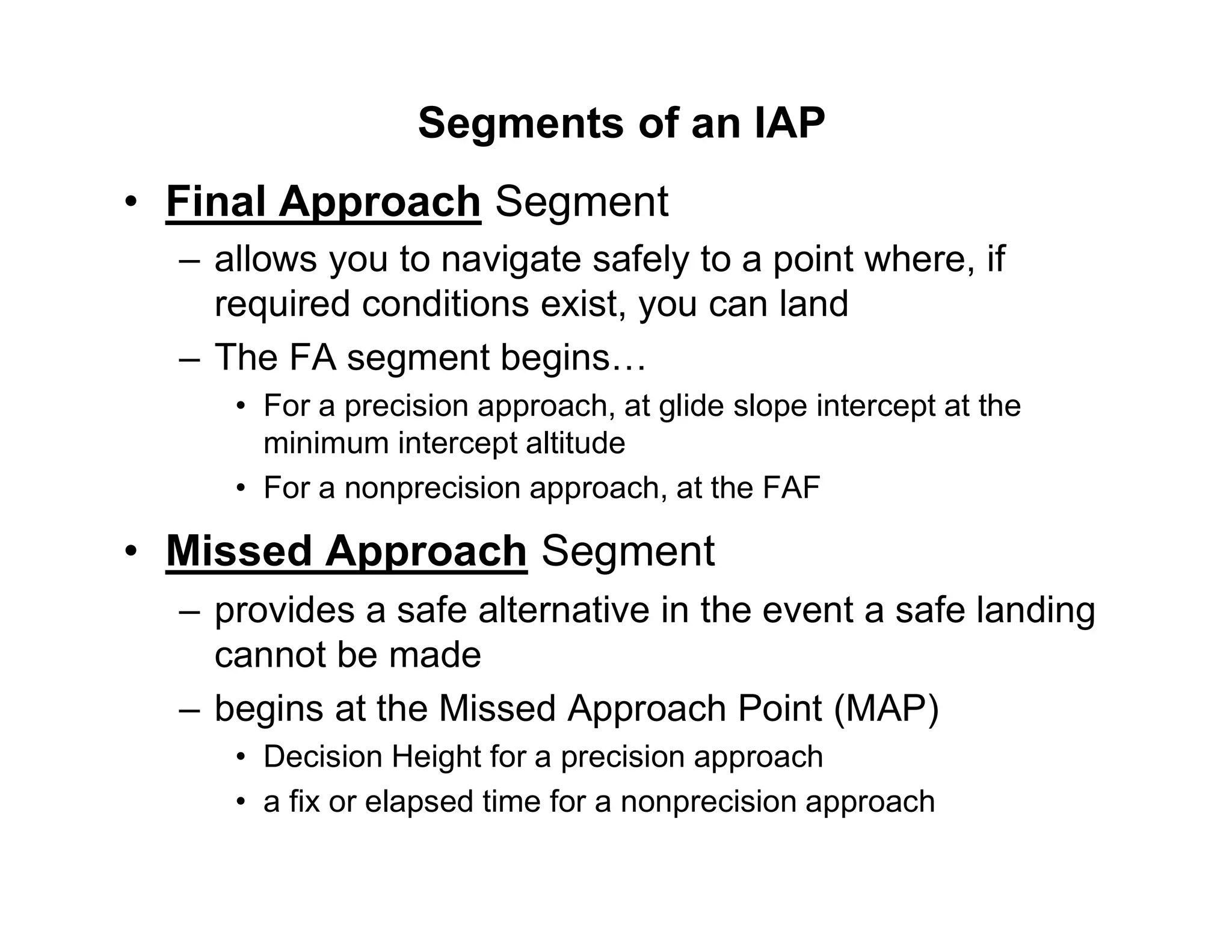
• Final Approach Segment
– allows you to navigate safely to a point where, if
required conditions exist, you can land
– The FA segment begins…
• For a precision approach, at glide slope intercept at the
minimum intercept altitude
• For a nonprecision approach, at the FAF
• Missed Approach Segment
– provides a safe alternative in the event a safe landing
cannot be made
– begins at the Missed Approach Point (MAP)
• Decision Height for a precision approach
• a fix or elapsed time for a nonprecision approach
Landing Minimums
Visibility andMinimum Altitude Requirements
-based on aircraft performance & equipment
Minimums provide on charts for
Circling Approaches – Approach different
runway than your final landing runway.
Sidestep maneuver – Clearance to land on a
parallel runway – next to approach runway.
Straight-In – Lower minima than both above.
Instrument Ground School2015
Other
Airport
Information
On Jeppesen
Charts…
(Remember: You can
find all info in the
AFD)
Jeppesen is convenient
because you don’t have
to carry the AFD with
you to find airport info.
37.
Instrument Ground School2015
Take-off & Alternate Minimums
When do we need an
alternate?
1-2-3 Rule
If +/- 1 Hr ETA
Ceilings are <2000
and or Visibility <3 sm
What are “precision” and
“non-precision Minimums
must be at the alternate?
Precision: 600 & 2
Non-precision: 800 & 2
PREPARING for theapproach.
ATC could clear you for any approach that the weather
and the equipment on your aircraft permit. Have all
appropriate charts readily at hand and ready to review
on clearance when you are given the approach.
1.Review as part of pre-flight planning, and
2.Perform a “Approach Chart Review” after you are
advise of what approach to expect.
42.
The “Approach Clearance”
•ATC will most likely clear you an approach that
will expedite the flow of traffic.
• Notify controller IMMEDIATELY if you want a
different approach. They may issue a desired
approach if traffic/time permits.
• If a specific approach is not specified; rather a
general “cleared for approach”, then you may
execute any one of the authorized IAPs for that
airport (does not permit a contact or visual
approach).
• Fly the “entire” approach including “Feeder
Routes” if it applies to your route.
43.
Straight-In Landing andApproaches
A “straight in landing” is given when the final approach
course is positioned within 30 degrees of the end of
runway and a minimum of maneuvering is required to
align with the runway. If the runway is NOT aligned then
you might get a “circle to land” approach instead of a
straight in approach.
A controller might say “Cleared for a straight-in approach”
which means you should not perform a procedure turn to
reverse your course. (example: “cleared for straight-in ILS
Runway 25 approach, circle to land runway 34.”). The
straight-in approach must provide a means of navigation
directly to the final approach course.
Instrument Ground School2015
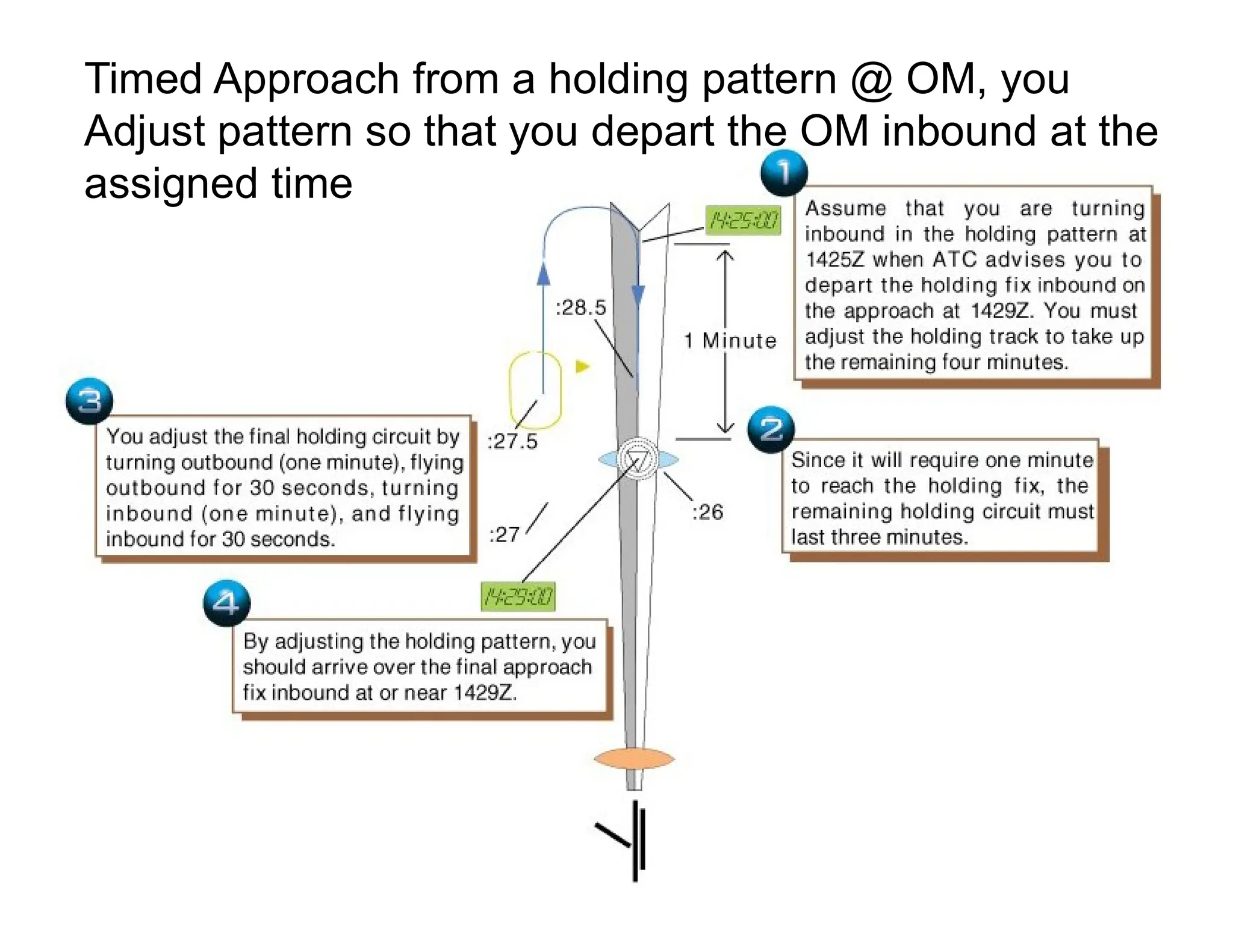
Timed Approach from a holding pattern @ OM, you
Adjust pattern so that you depart the OM inbound at the
assigned time
51.
Instrument Ground School2015
Final Approach: MUST KNOW when you can safely continue
below minimum altitude designated for that approach!
You MAY NOT operate below the authorized MDA or continue an
approach below the authorized DA unless flight visibility is not less
than the visibility prescribed in the standard instrument approach
procedure being used. This requirement is also required for
landing
At least one of the following visual references for the intended
runway is distinctly visible and identifiable: The Approach Light
system, The Threshold, The Threshold Markings, The
Threshold Lights, The Runway End Identifier Lights, The
Visual Approach Slope indicator, The Touchdown Zone or
Touchdown Zone Markings, The Touchdown Zone Lights, The
Runway or Runway Markings, or The Runway Lights.
SIDESTEP MANEUVER
• Someairports have published “Sidestep”
maneuvers that allow you to make the
approach on one of a set of parallel
runways and as soon as possible after
having sited the other parallel runway,
executing a landing on that runway.
Approach Charts: SummaryChecklist
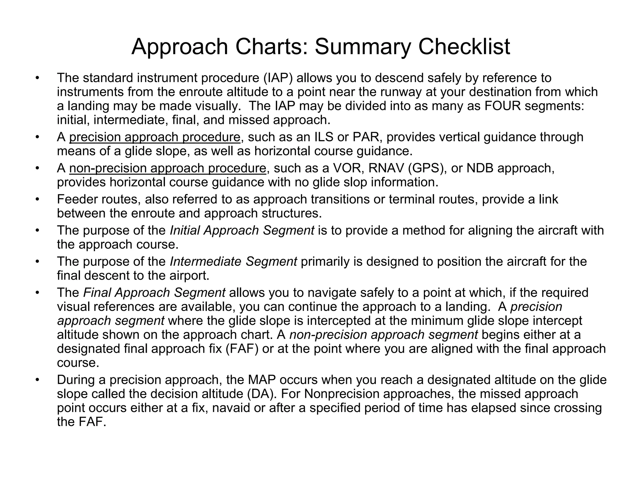
• The standard instrument procedure (IAP) allows you to descend safely by reference to
instruments from the enroute altitude to a point near the runway at your destination from which
a landing may be made visually. The IAP may be divided into as many as FOUR segments:
initial, intermediate, final, and missed approach.
• A precision approach procedure, such as an ILS or PAR, provides vertical guidance through
means of a glide slope, as well as horizontal course guidance.
• A non-precision approach procedure, such as a VOR, RNAV (GPS), or NDB approach,
provides horizontal course guidance with no glide slop information.
• Feeder routes, also referred to as approach transitions or terminal routes, provide a link
between the enroute and approach structures.
• The purpose of the Initial Approach Segment is to provide a method for aligning the aircraft with
the approach course.
• The purpose of the Intermediate Segment primarily is designed to position the aircraft for the
final descent to the airport.
• The Final Approach Segment allows you to navigate safely to a point at which, if the required
visual references are available, you can continue the approach to a landing. A precision
approach segment where the glide slope is intercepted at the minimum glide slope intercept
altitude shown on the approach chart. A non-precision approach segment begins either at a
designated final approach fix (FAF) or at the point where you are aligned with the final approach
course.
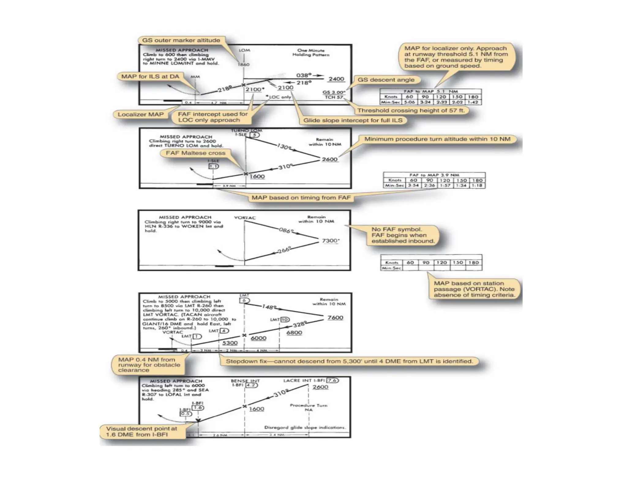
• During a precision approach, the MAP occurs when you reach a designated altitude on the glide
slope called the decision altitude (DA). For Nonprecision approaches, the missed approach
point occurs either at a fix, navaid or after a specified period of time has elapsed since crossing
the FAF.
63.
Approach Charts: SummaryChecklist
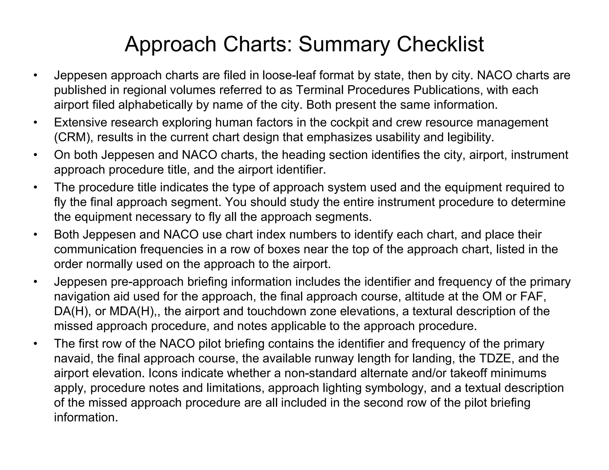
• Jeppesen approach charts are filed in loose-leaf format by state, then by city. NACO charts are
published in regional volumes referred to as Terminal Procedures Publications, with each
airport filed alphabetically by name of the city. Both present the same information.
• Extensive research exploring human factors in the cockpit and crew resource management
(CRM), results in the current chart design that emphasizes usability and legibility.
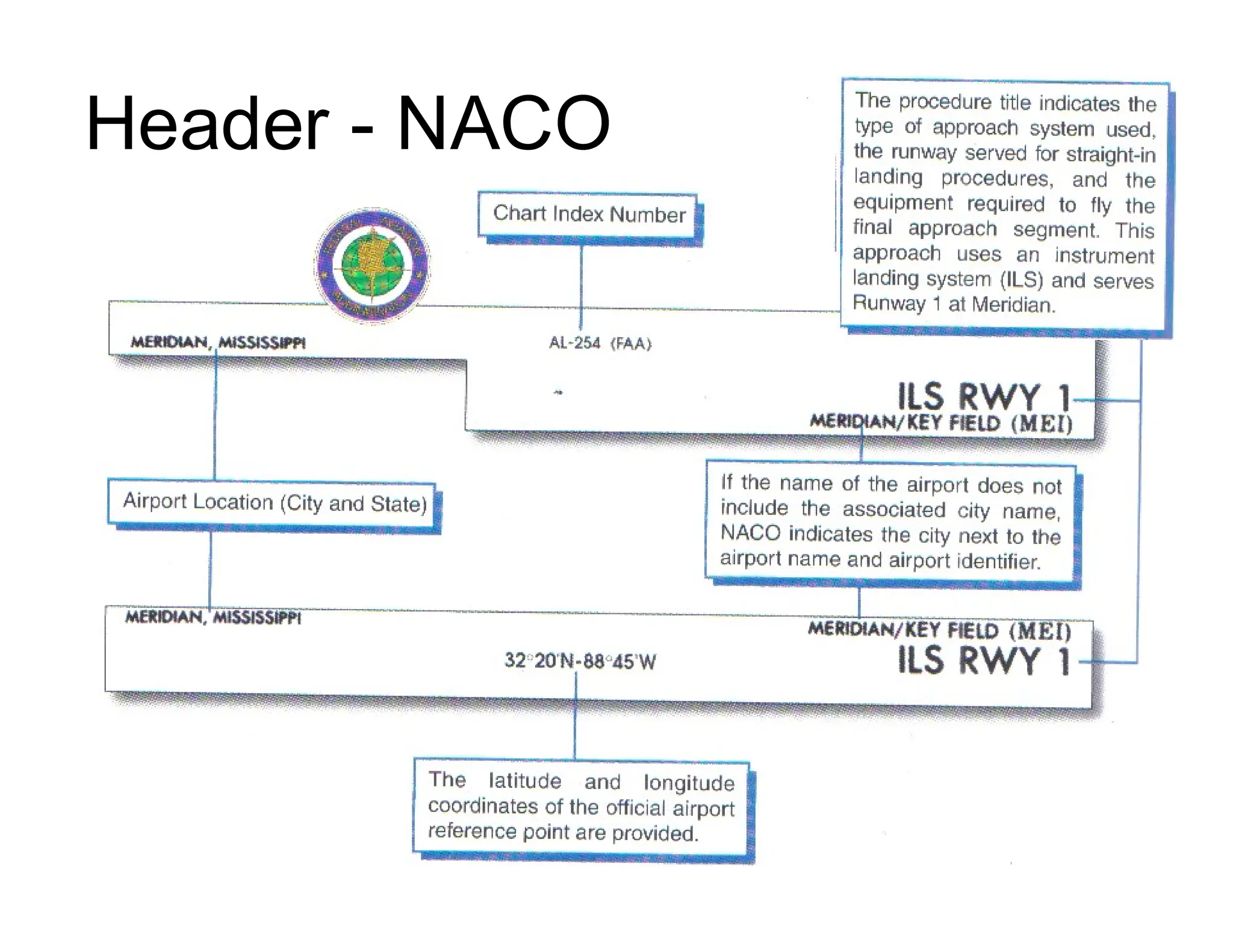
• On both Jeppesen and NACO charts, the heading section identifies the city, airport, instrument
approach procedure title, and the airport identifier.
• The procedure title indicates the type of approach system used and the equipment required to
fly the final approach segment. You should study the entire instrument procedure to determine
the equipment necessary to fly all the approach segments.
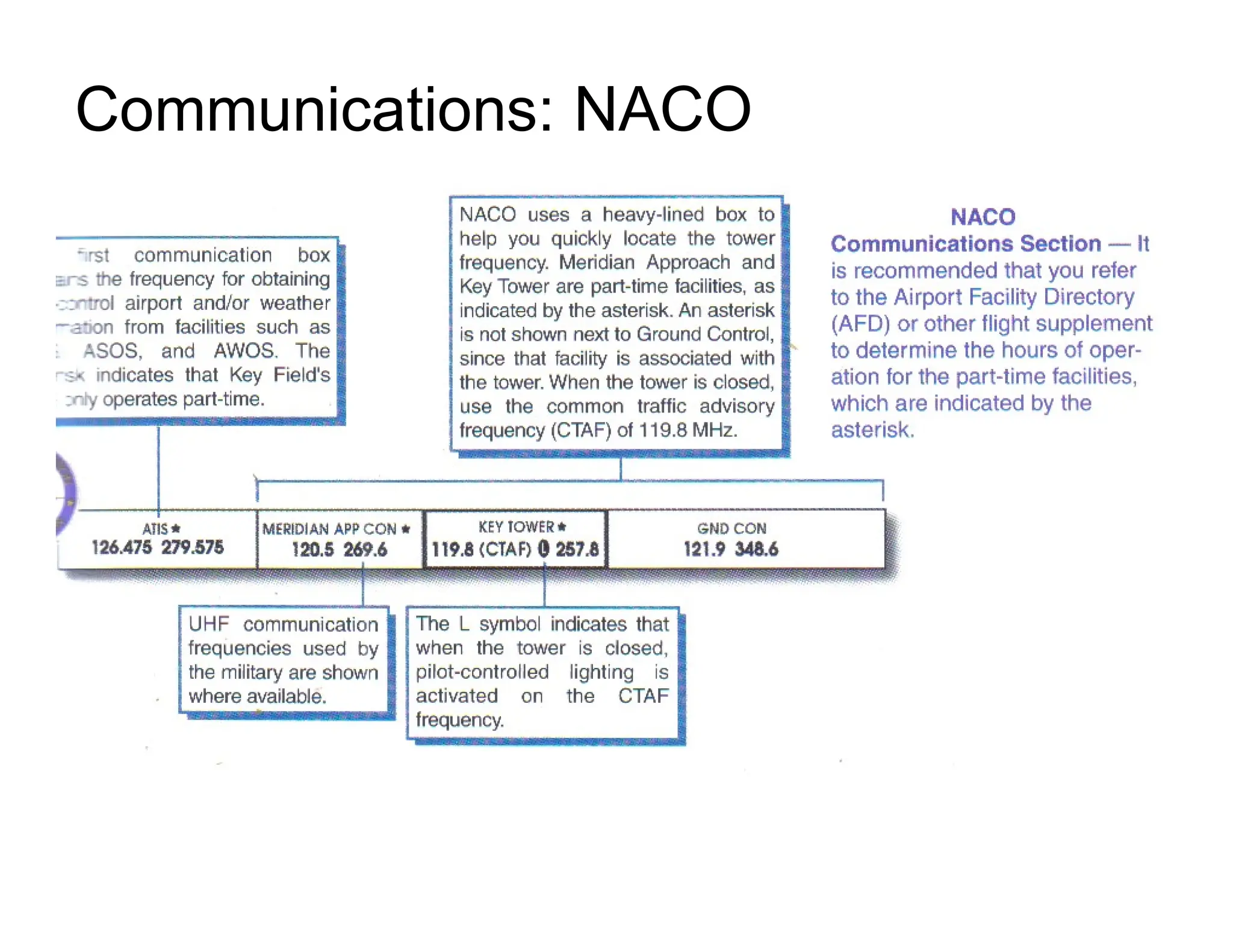
• Both Jeppesen and NACO use chart index numbers to identify each chart, and place their
communication frequencies in a row of boxes near the top of the approach chart, listed in the
order normally used on the approach to the airport.
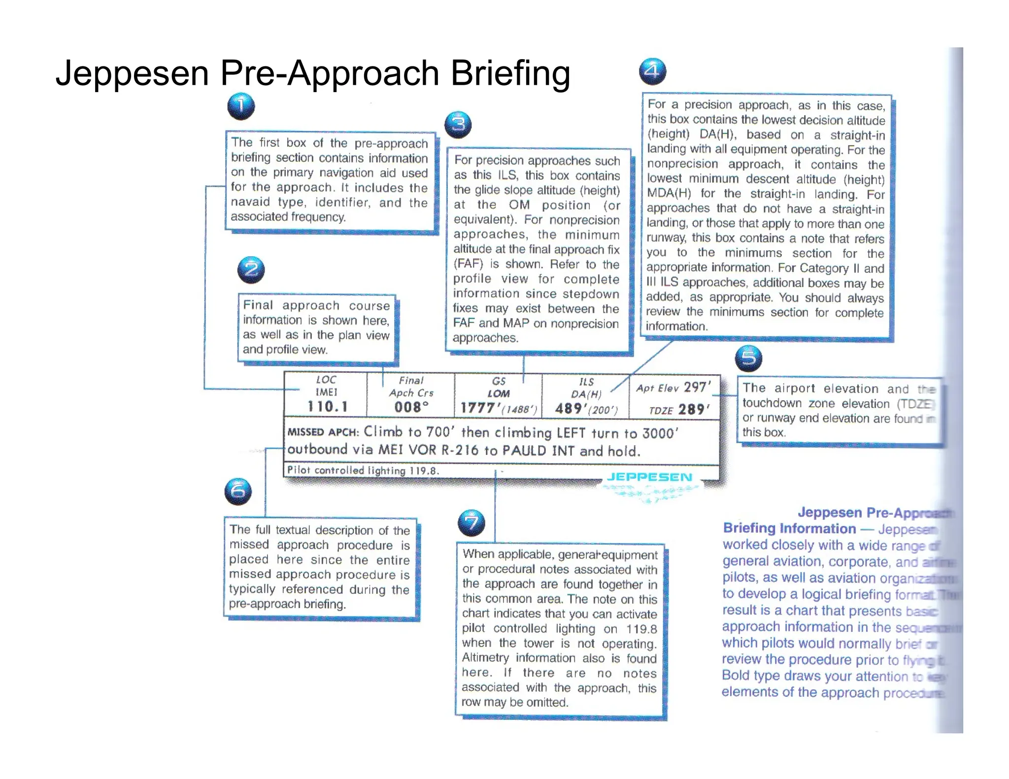
• Jeppesen pre-approach briefing information includes the identifier and frequency of the primary
navigation aid used for the approach, the final approach course, altitude at the OM or FAF,
DA(H), or MDA(H),, the airport and touchdown zone elevations, a textural description of the
missed approach procedure, and notes applicable to the approach procedure.
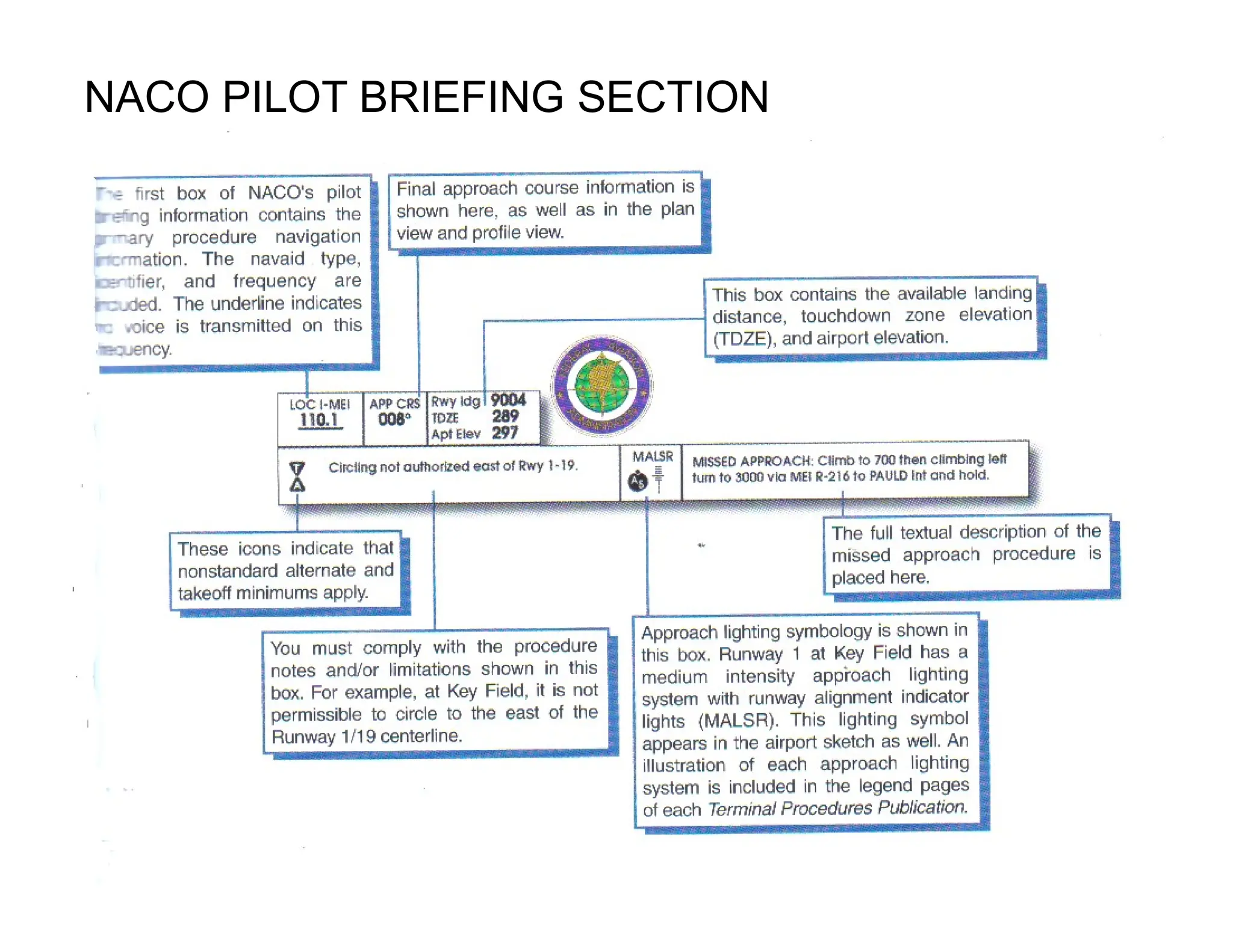
• The first row of the NACO pilot briefing contains the identifier and frequency of the primary
navaid, the final approach course, the available runway length for landing, the TDZE, and the
airport elevation. Icons indicate whether a non-standard alternate and/or takeoff minimums
apply, procedure notes and limitations, approach lighting symbology, and a textual description
of the missed approach procedure are all included in the second row of the pilot briefing
information.
64.
Approach Charts: SummaryChecklist
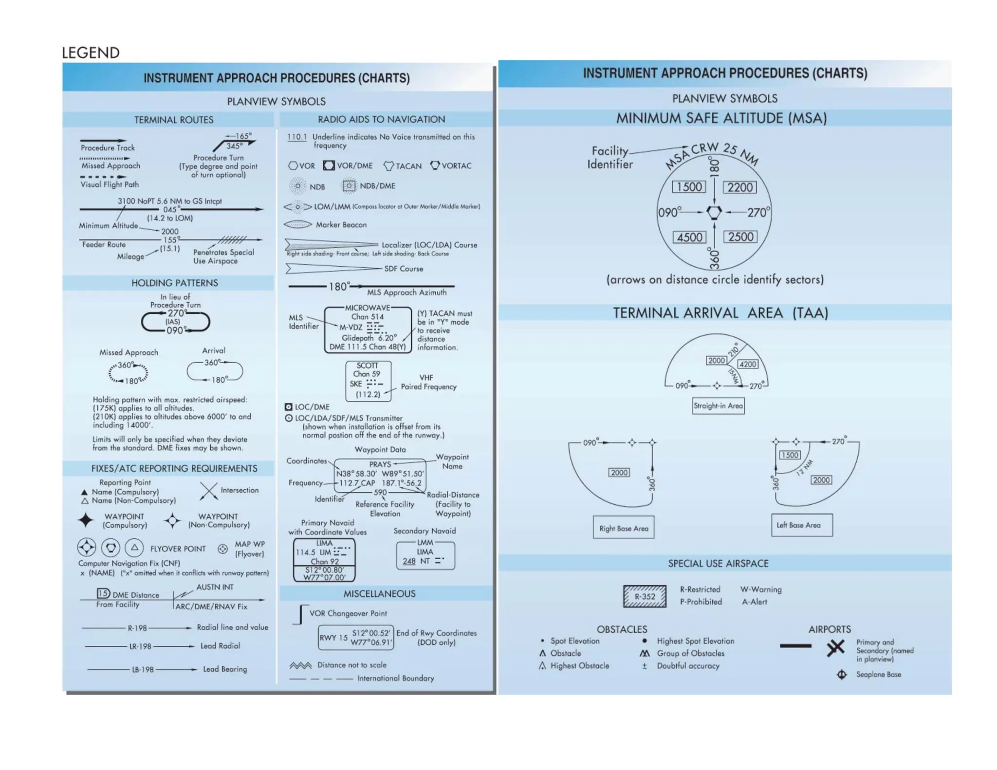
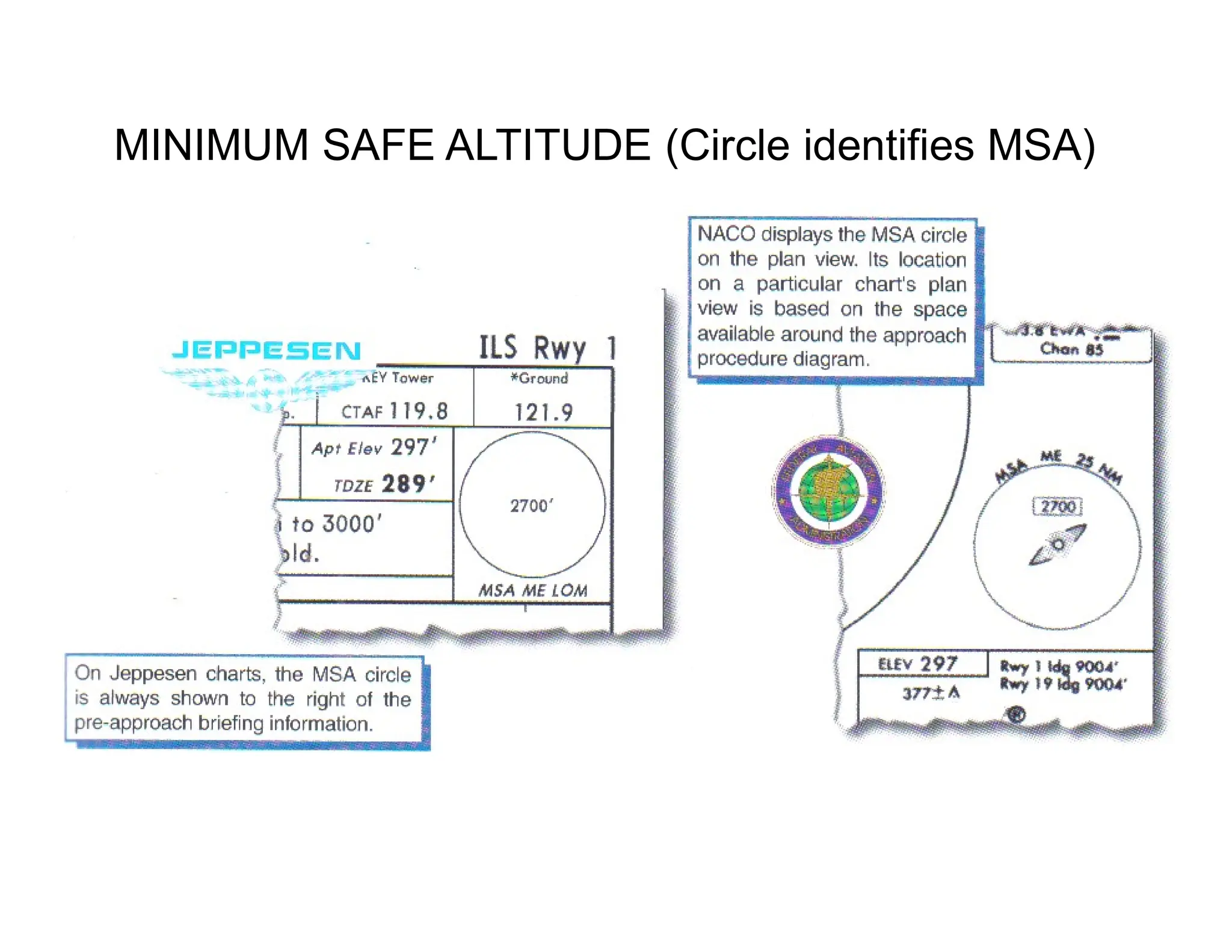
• The minimum safe altitude (MSA) shown on approach chars provides 1,000 feet of obstruction
clearance within 25 NMs of the indicated facility unless some other distance is specified.
• Operating at or above the MSA does not guarantee navigation or communication coverage and
the MSA is designated for use only in an emergency or during VFR flight, such as at night.
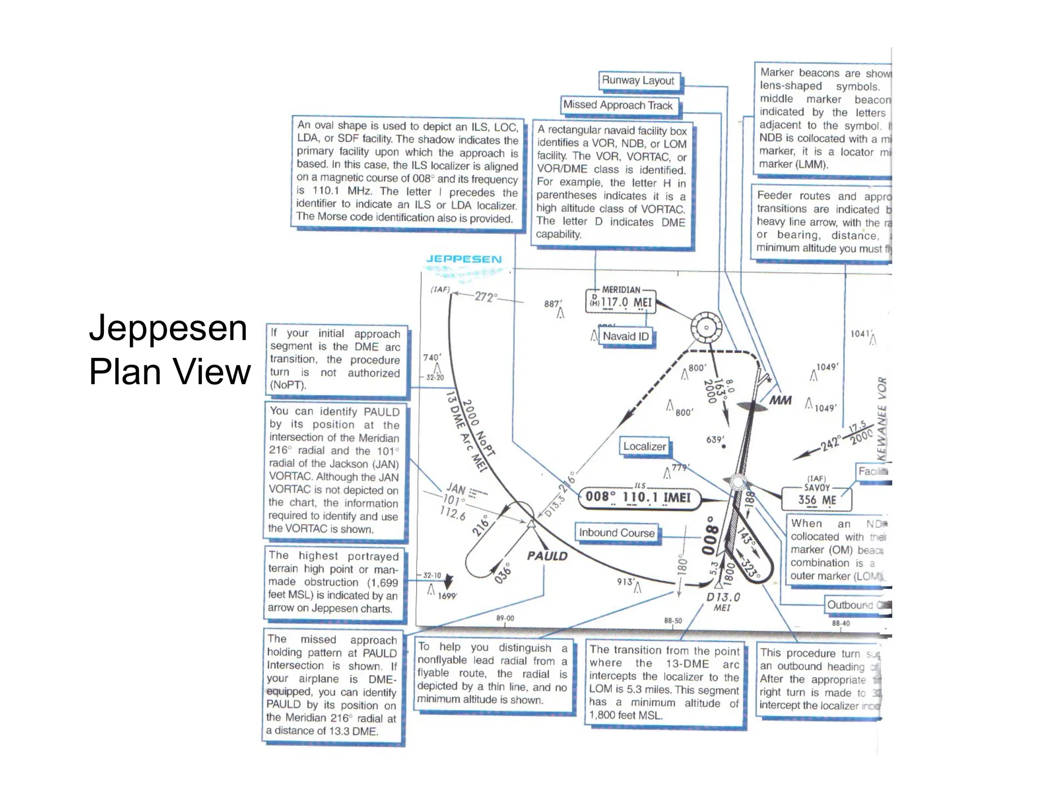
• The Plan View is an overhead presentation of the entire approach procedure.
• There may be higher uncharted terrain or man-made structures than those depicted on the
approach chart. Adherence to the minimum altitudes depicted on the approach charts provides
terrain and obstacle clearance.
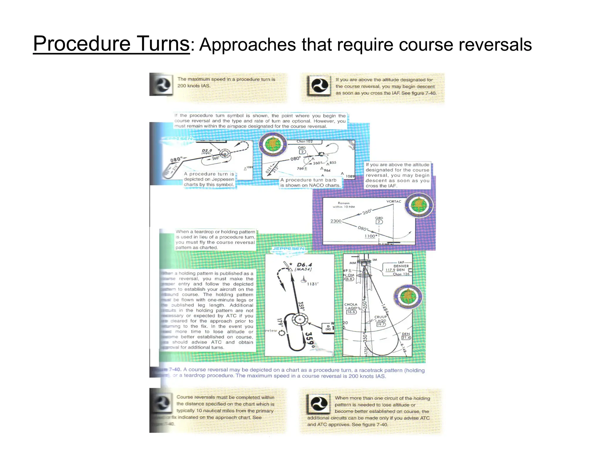
• When the procedure turn is depicted on the plan viw, it mean you MAY reverse course an way
you desire as long as the turn is made on the same side of the approach course as the symbol,
the turn is completed within the distance specified in the profile view, and you remain within
protected airspace.
• If a holding or teardrop pattern is shown instead of a procedure turn, it is the only approved
method of course reversal, If a procedure turn, holding pattern, or teardrop is NOT shown, a
course reversal is NOT authorized.
• On selected Jeppesen and NACO approach charts plan views, generalized terrain contour line,
values, and gradient tints may be depicted in brown. This information does not ensure
clearance above or around the terrain and must not be relied upon for descent below the
minimum altitudes depicted on the approach procedures.
• The profile view shows the approach from the side and displays the flight path and facility, as
well as minimum altitudes in feet MSL
• The touchdown zone elevation (TDZE) is the highest elevation in the first 3,000 feet of the
landing surface.
65.
Approach Charts: SummaryChecklist
• The height above touchdown (TAT) is measured from the touchdown zone elevation or the
threshold elevation of the runway served by the approach. The height above airport (HAA) is
measured above the official airport elevation, which is the highest point of an airport’s usable
runways.
• The threshold crossing height (TCH) is the altitude at which you cross the runway threshold
when established on the glide slope centerline.
• Many approaches incorporate one or more stepdown fixes, which are commonly used along
approach segments to allow you to descend to a lower altitude. Your ability to identify selected
stepdown fixes may permit lower landing minimums in some cases.
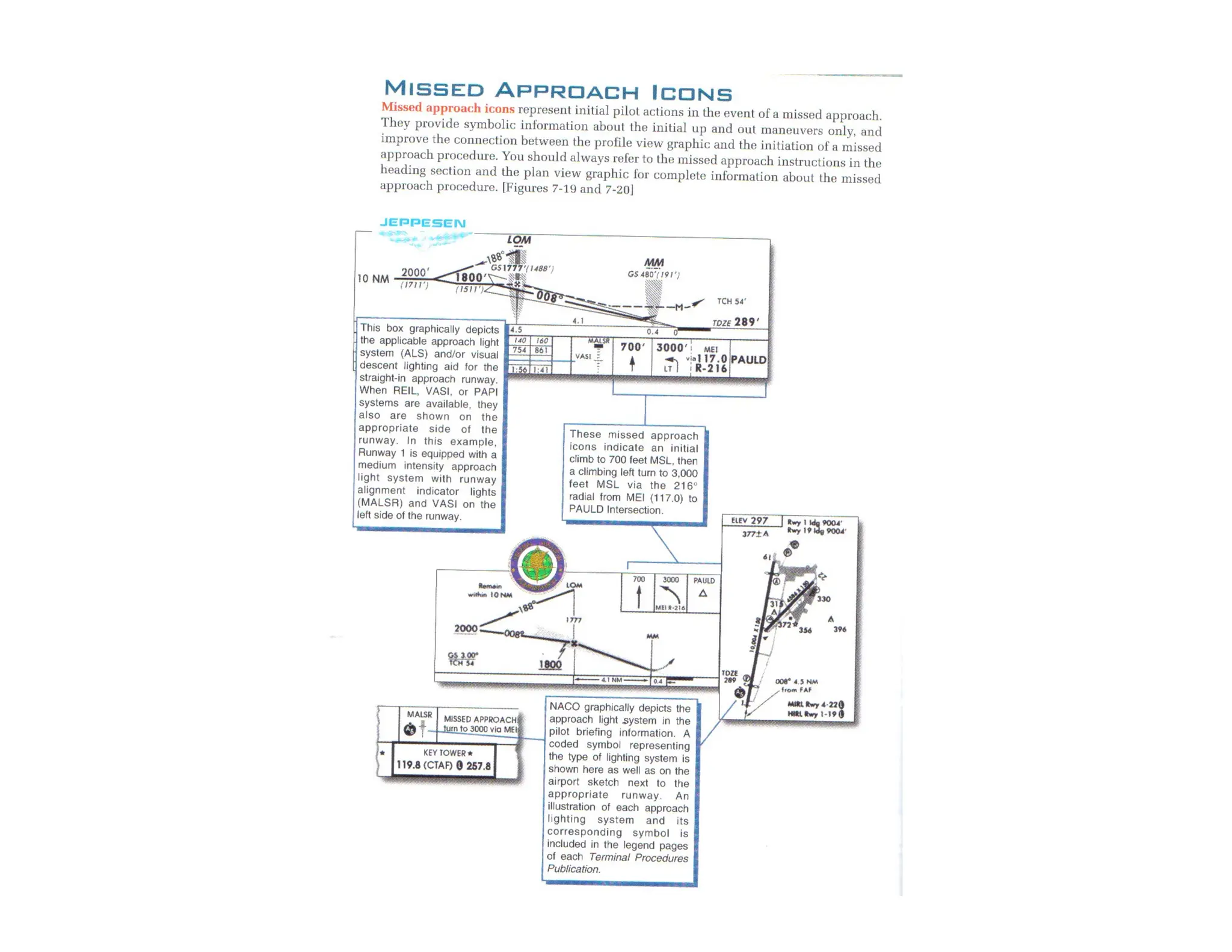
• A visual descent point (VDP) represents the point from which you can make a normal descent
to a landing, assuming you have the runway in sight and you are starting from the minimum
descent altitude. Missed approach icons provide symbolic information about the initial up and
out maneuver only. You should always refer to the missed approach instructions in the heading
section and the plan view graphic for complete information about the missed approach
procedure.
• The conversion table on Jeppesen charts and the time and speed table on NACO chars provide
various elapse time to the MAP for non-precision approaches based on groundspeed.
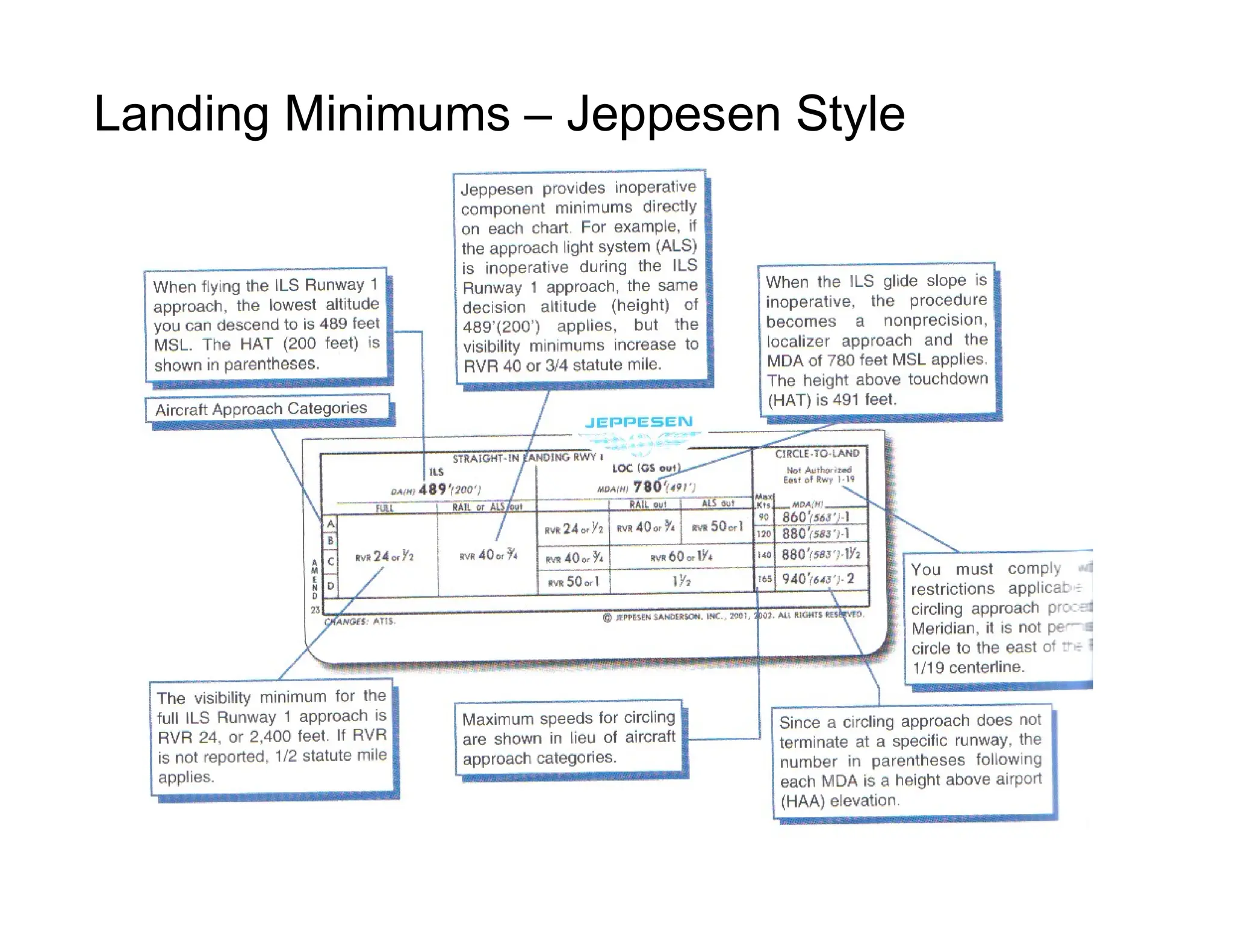
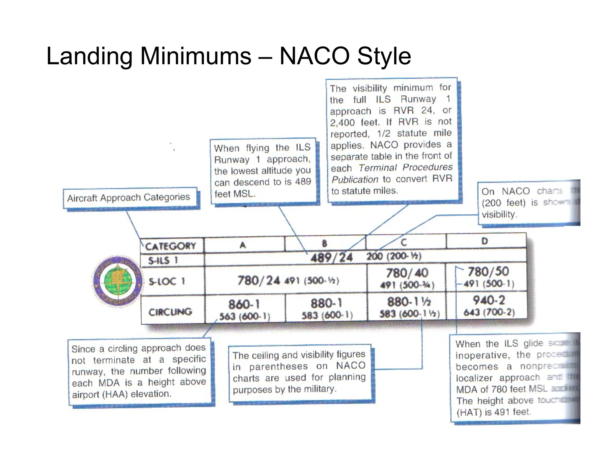
• Landing minimums, which contain both minimum visibility and minimum altitude requirements,
have been established for each approach at a given airport.
• A circling approach is a procedure that involves executing an approach to one runway and then
landing on another. Separate circle-to-land minimums are published in the landing minimums
section if this procedure is authorized.
66.
Approach Charts: SummaryChecklist
• During a sidestep maneuver, you are cleared for an approach to one runway with clearance to
land on a parallel runway.
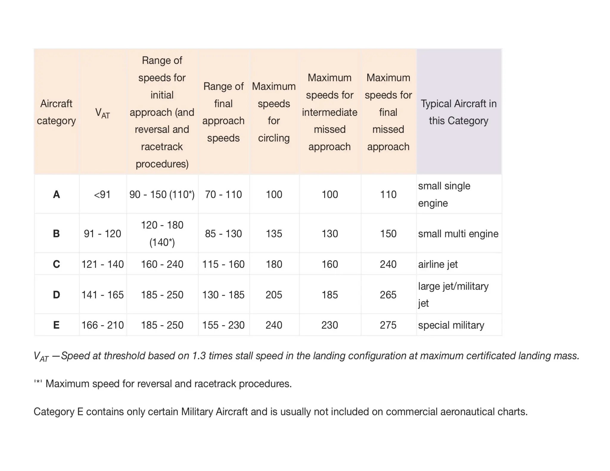
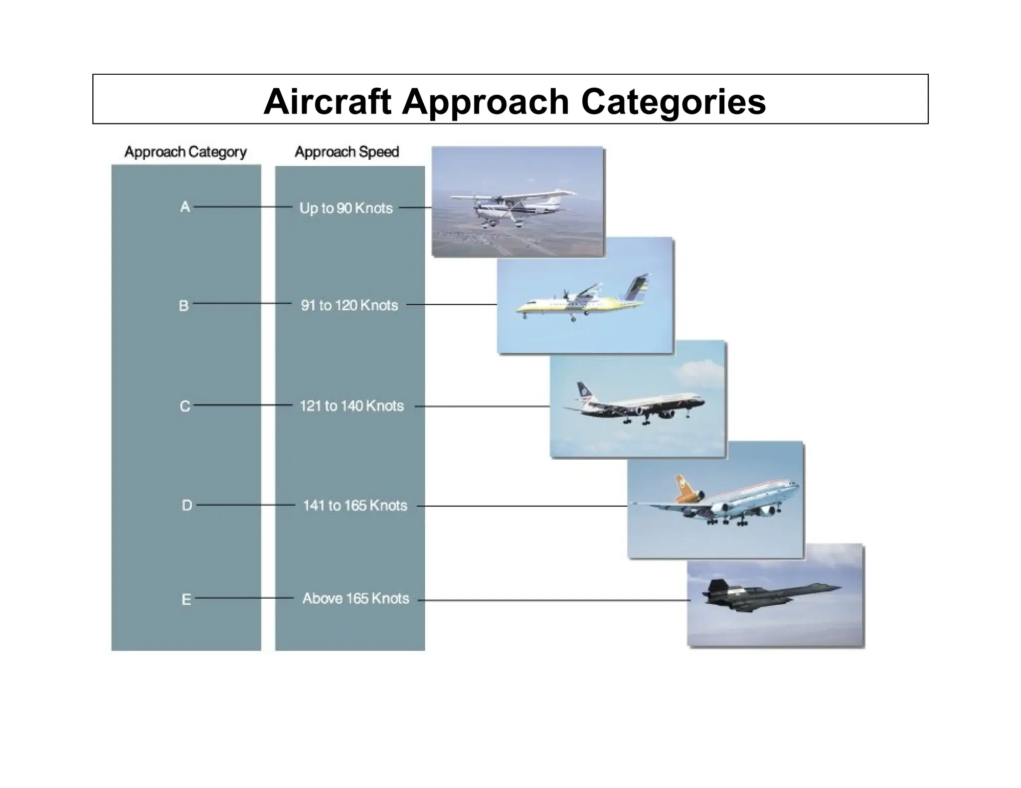
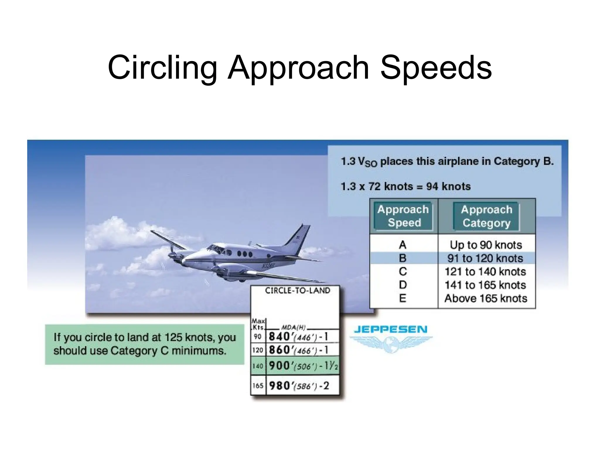
• Each aircraft is placed into an approach category based on its computed approach speed. This
speed equals 130% of the aircrafts power-off stall speed in a landing configuration (1.3 VS0).
• Visibility listed on approach charts is in statue miles, usually as a prevailing visibility reported by
an accredited observer such as tower or weather personnel, or in hundreds of feet determined
through the use of runway visual range (RVR) equipment.
• Landing minimums usually increase when a required component or visual aid becomes inop.
• Regulations permit you to make substitutions for certain components when that component is
inop or is not utilized during an approach
• NACO places an airport sketch in the lower left or right corner and provides a full-page airport
diagram for selected airports.
• The airport reference point (ARP), shown on Jeppesen charts, is the approximate geometric
center of all usable runways services. The official lat/long coordinates are derived form the
ARP.
• If the forecast weather at your ETA, plus or minus 1 hour, indicates a ceiling of less than 2,000
feet or visibility of less than 3 miles, you must list an alternate airport on your flight plan
• Standard alternate minimums for precision approaches are a 600-foot ceiling and 2 statue miles
visibility. For nonprecision approaches, an 800-foot ceiling and 2 statue miles apply..
• Jeppesen lists both standard and nonstandard takeoff and alternate minimums and departure
procedures on the airport chart. NACO charts refer you to the Terminal Procedures Publication
to find standard takeoff and nonstandard alternate minimums.
• Jeppesen classic and NACO traditional charts feature essentially the same info.
67.
Approach Procedures: SummaryChecklist
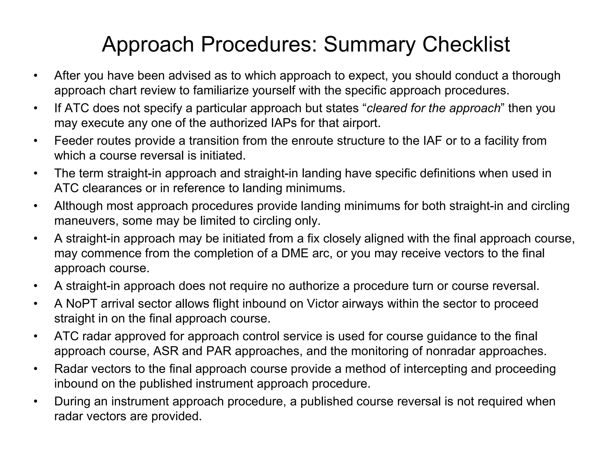
• After you have been advised as to which approach to expect, you should conduct a thorough
approach chart review to familiarize yourself with the specific approach procedures.
• If ATC does not specify a particular approach but states “cleared for the approach” then you
may execute any one of the authorized IAPs for that airport.
• Feeder routes provide a transition from the enroute structure to the IAF or to a facility from
which a course reversal is initiated.
• The term straight-in approach and straight-in landing have specific definitions when used in
ATC clearances or in reference to landing minimums.
• Although most approach procedures provide landing minimums for both straight-in and circling
maneuvers, some may be limited to circling only.
• A straight-in approach may be initiated from a fix closely aligned with the final approach course,
may commence from the completion of a DME arc, or you may receive vectors to the final
approach course.
• A straight-in approach does not require no authorize a procedure turn or course reversal.
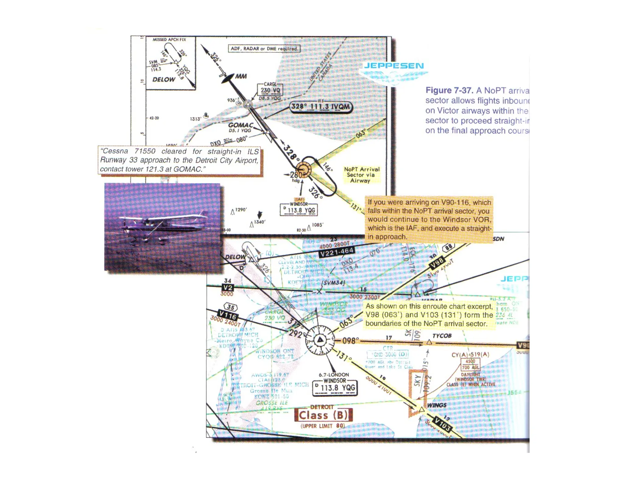
• A NoPT arrival sector allows flight inbound on Victor airways within the sector to proceed
straight in on the final approach course.
• ATC radar approved for approach control service is used for course guidance to the final
approach course, ASR and PAR approaches, and the monitoring of nonradar approaches.
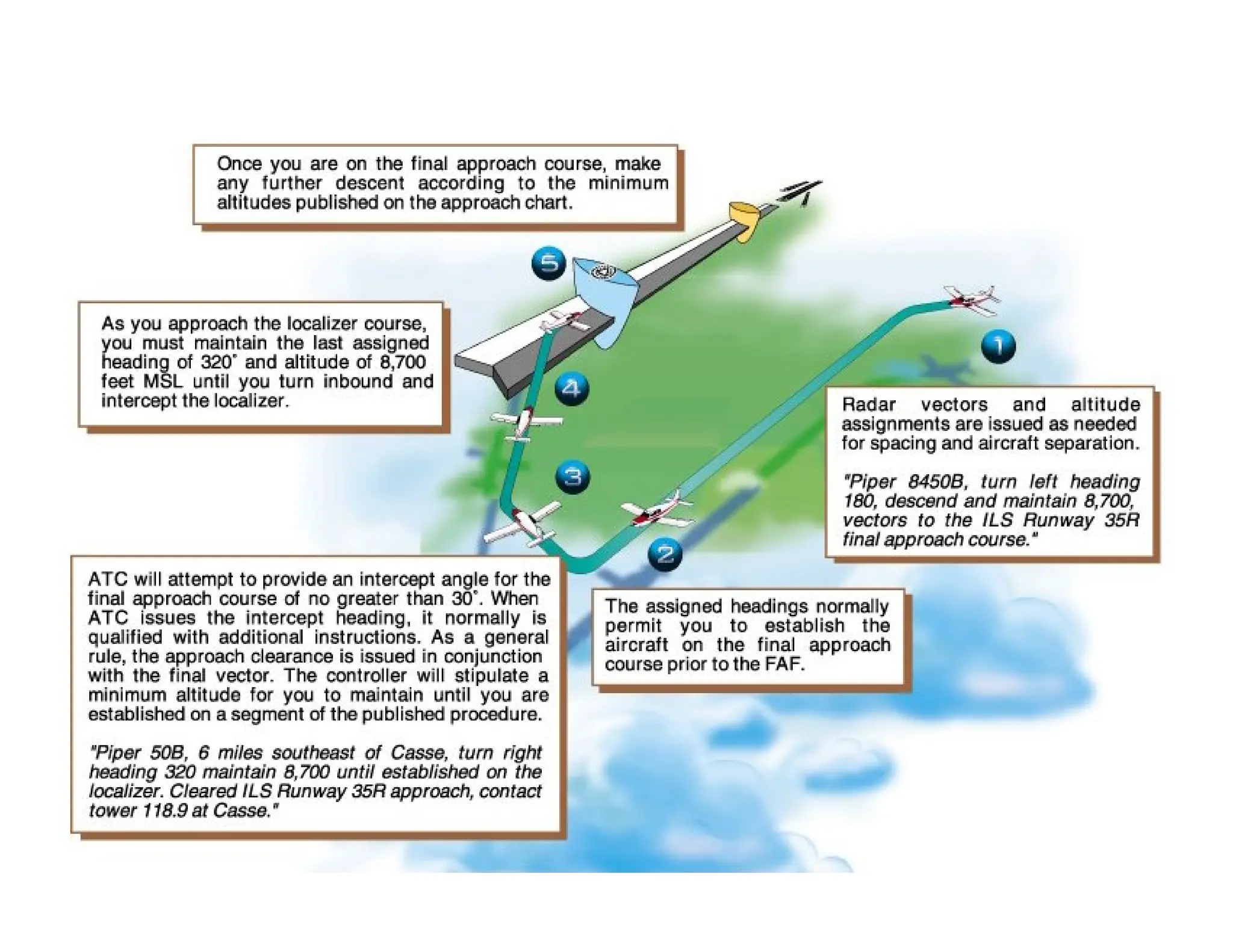
• Radar vectors to the final approach course provide a method of intercepting and proceeding
inbound on the published instrument approach procedure.
• During an instrument approach procedure, a published course reversal is not required when
radar vectors are provided.
68.
Approach Procedures: SummaryChecklist
• If it becomes apparent the heading assigned by ATC will cause you to pass through the final
approach course, you should maintain that heading and question the controller.
• A course reversal may be depicted on a chart as a procedure turn, a racetrack patter (holding
pattern), or a teardrop procedure. The maximum speed in a course reversal is 200 knots IAS.
• When more than one circuit of a holding pattern is needed to lose altitude or become better
established on course, the additional circuits can be made only if you advise ATC and ATC
approves.
• Timed approaches from a holding fix are generally conducted at airports where the radar
system for traffic sequencing is out of service or is not available and numerous aircraft are
waiting for approach clearance.
• When timed approaches are in progress, you will be given advance notice of the time you
should leave the holding fix.
• To descend below the DA or MDA, you must be able to identify specific visual references, as
well as comply with visibility and operating requirements which are listed in the regulations.
• You should usually descend at a rate that allows you to reach the MDA prior to the MAP so that
you are in a position to establish a normal rate of descent from the MDA to the runway, using
normal maneuvers.
• VASI lights can help you maintain the proper descent angle to the runway once you have
established visual contact with the runway environment.
• Visual illusions are the product of various runway conditions, terrain features, and atmospheric
phenomena which can create a sensation of incorrect height above the runway or incorrect
distance from the runway threshold.
69.
Approach Procedures: SummaryChecklist
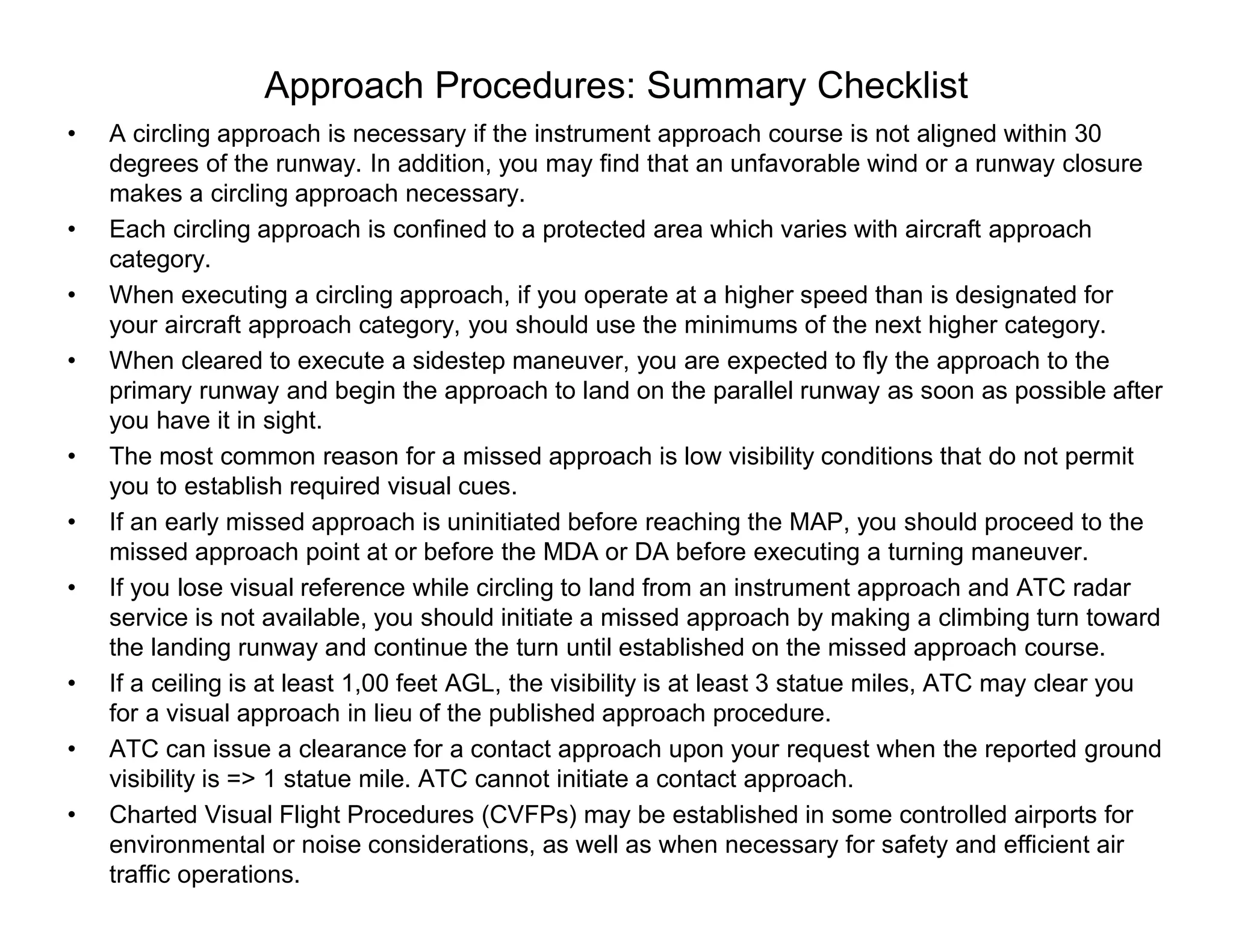
• A circling approach is necessary if the instrument approach course is not aligned within 30
degrees of the runway. In addition, you may find that an unfavorable wind or a runway closure
makes a circling approach necessary.
• Each circling approach is confined to a protected area which varies with aircraft approach
category.
• When executing a circling approach, if you operate at a higher speed than is designated for
your aircraft approach category, you should use the minimums of the next higher category.
• When cleared to execute a sidestep maneuver, you are expected to fly the approach to the
primary runway and begin the approach to land on the parallel runway as soon as possible after
you have it in sight.
• The most common reason for a missed approach is low visibility conditions that do not permit
you to establish required visual cues.
• If an early missed approach is uninitiated before reaching the MAP, you should proceed to the
missed approach point at or before the MDA or DA before executing a turning maneuver.
• If you lose visual reference while circling to land from an instrument approach and ATC radar
service is not available, you should initiate a missed approach by making a climbing turn toward
the landing runway and continue the turn until established on the missed approach course.
• If a ceiling is at least 1,00 feet AGL, the visibility is at least 3 statue miles, ATC may clear you
for a visual approach in lieu of the published approach procedure.
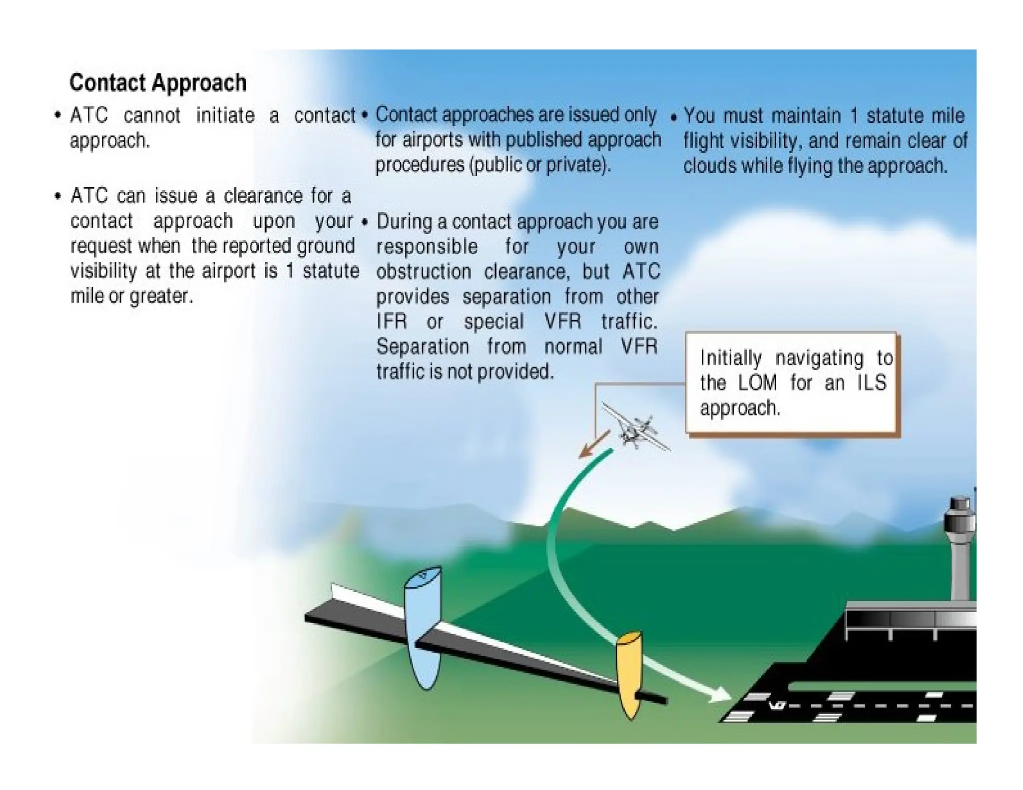
• ATC can issue a clearance for a contact approach upon your request when the reported ground
visibility is => 1 statue mile. ATC cannot initiate a contact approach.
• Charted Visual Flight Procedures (CVFPs) may be established in some controlled airports for
environmental or noise considerations, as well as when necessary for safety and efficient air
traffic operations.