This paper presents a steganography method that utilizes a developed particle swarm optimization (PSO) algorithm to securely embed secret messages in cover images using the least significant bit (LSB) technique. The developed PSO algorithm effectively identifies optimal positions for embedding and ensures high-quality stego-images, with peak signal-to-noise ratio (PSNR) values reported as high as 44.87 dB. The method demonstrates resilience against common noise attacks, enhancing data security during transmission over insecure channels.
![International Journal of Electrical and Computer Engineering (IJECE)
Vol. 8, No. 2, April 2018, pp. 1156~1168
ISSN: 2088-8708, DOI: 10.11591/ijece.v8i2.pp1156-1168 1156
Journal homepage: http://iaescore.com/journals/index.php/IJECE
Information Hiding using LSB Technique based on Developed
PSO Algorithm
Wisam Abed Shukur1
, Khalid Kadhim Jabbar2
1
Computer Science Dept., College of Education for Pure Sciences/Ibn Al-Haitham, University of Baghdad, Iraq
2
Computer Science Department, College of Education, University of Mustansiryia, Iraq
Article Info ABSTRACT
Article history:
Received Jul 28, 2017
Revised Oct 7, 2017
Accepted Oct 20, 2017
Generally, The sending process of secret information via the transmission
channel or any carrier medium is not secured. For this reason, the techniques
of information hiding are needed. Therefore, steganography must take place
before transmission. To embed a secret message at optimal positions of the
cover image under spatial domain, using the developed particle swarm
optimization algorithm (Dev.-PSO) to do that purpose in this paper based on
Least Significant Bits (LSB) using LSB substitution. The main aim of (Dev.
-PSO) algorithm is determining an optimal paths to reach a required goals in
the specified search space based on disposal of them, using (Dev.-PSO)
algorithm produces the paths of a required goals with most efficient and
speed. An agents population is used in determining process of a required
goals at search space for solving of problem. The (Dev.-PSO) algorithm is
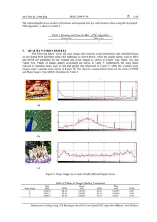
applied to different images; the number of an image which used in the
experiments in this paper is three. For all used images, the Peak Signal to
Noise Ratio (PSNR) value is computed. Finally, the PSNR value of the
stego-A that obtained from blue sub-band colo is equal (44.87) dB, while the
stego-B is equal (44.45) dB, and the PSNR value for the stego-C is
(43.97)dB, while the vlue of MSE that obtained from the same color sub-
bans is (0.00989), stego-B equal to (0.01869), and stego-C is (0.02041).
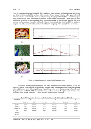
Furthermore, our proposed method has ability to survive the quality for the
stego image befor and after hiding stage or under intended attack that used in
the existing paper such as Gaussian noise, and salt & pepper noise.
Keyword:
Cover image
Developed PSO algorithm
Search space
Steganography
Stego image
Copyright © 2018 Institute of Advanced Engineering and Science.
All rights reserved.
Corresponding Author:
Wisam Abed Shukur,
Computer Science Dept.,
College of Education For Pure Sciences/Ibn Al-Haitham,
Baghdad University,
Baghdad, Iraq.
Email: wisam_shukur@yahoo.com
1. INTRODUCTION
The big losses and digital signal transmission due to unwanted access of data with the high demand
in both; the security of data becomes an imperative and critical concept. For data securing and preventing
them from unauthorized access, encryption and steganography processes is used [1]. The most important
concept in any communication process between sender and receiver via the transmission channel is security.
The using of advance technology inside the World Wide Web (WWW) to exchange information leads to
increase the challenges and risks. However, the management of challenges and risks is possible with using an
advanced technology of secure networks but these technologies are not enough for information security over
communication between sender and receiver. Therefore, additional mechanisms of security are needed to
secure information. [2], an origin of steganography word is Greek, steganography means "covered writing" or
"concealed writing" [3]. The main difference between steganography and cryptography is keeping the](https://image.slidesharecdn.com/v587oct1728jul8110-10804-1-ed-201110085336/85/Information-Hiding-using-LSB-Technique-based-on-Developed-PSO-Algorithm-1-320.jpg)
![Int J Elec & Comp Eng ISSN: 2088-8708
Information Hiding using LSB Technique Based On Developed PSO Algorithm (Wisam Abed Shukur)
1157
existence of a message secret. The shared goal of steganography and cryptography is information protecting
against malicious or unwanted persons or parties [4]. An embedding algorithm embeds secret information in a
host image; the hiding process is performed with selected private or secret key to increase the complexity of
hiding process.
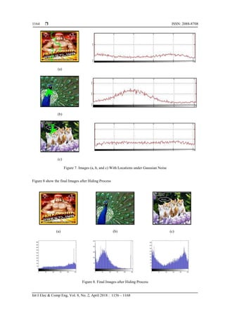
Figure 1 shows a generic model of an image steganographic. After embedding process, transmitting a
stego-image to the receiver via transmission medium or communication channel is performed. The receiver
extracts hidden information which embedded using embedding technique by the sender from received stego-
image with using same or another key according to type of steganography that selected initially. The receiver
will apply an extraction technique on stego-image for that purpose. Via transmitting a stego-image from the
sender to the receiver, there are many unauthorized persons or parties that notice a stego-image but without
extracting the hidden contents of a stego-image [5]. The embedding techniques are selected according to type
of domain, the types of embedding domains are spatial and frequency domains. The types of host or cover are
text, audio, image and video [6]. The spatial domain is used in this work. In the spatial domain, the secret
message is embedded in the specified positions by adding or replacing the bits of selected bits of cover or
host image. Generally, the typical characteristics of spatial domain are all methods related to this domain are
very easy and simple to understand, the execution time is low, a secret message is applied to the pixels
directly without transforming an original image and finally a secret message is embedded in the region or
part of host or cover image that considered as redundant [7]. There are many techniques related to the spatial
domain of an image steganography such as Least Significant Bit (LSB) and Most Significant Bit (MSB)
techniques. The LSB technique is used in the existing papper. This technique embeds secret information in
the least significant bit of selected pixels of the host image. So, it exploits the point which the precision in
several image formats is greater than the human vision. The variations of image colors are indistinguishable
by human vision [8].
Figure 1. Generic Model of an Image Steganographic
2. THE RELATED ATTEMPTS
The techniques of data hiding are classified into LSB substitution of spatial domain; LSB is similar
to many methods as Pixel Value Differencing (PVD). The principle work of LSB substitution method is
replacing LSB’s of pixels values within image that considered as cover to get stego image, this is most
commonly used. Secret bits of sensitive information are replaced within LSB’s bits of cover image. When
result of matching process is not obtain? Then the adding or subtracting operations for value of cover image
pixel are performed for one randomly. The core work of PVD based methods is computing the difference of
two pixels that are consecutive to specify the depth of embedded bits. Chang et al. [9] the strategy of
dynamic programming that proposed is pick the optimal or best via all tables of substitution efficiently. In
[10] the PSO is used to hide a secret information or message in an image based on LSB and in [11] an image
hiding within another image using LSB technique. These methods based PSO algorjthm are better results
than other standard LSB techniques. The technique that uses dynamic programming and genetic algorithms
are based on effects that considered as visual for human. The data hiding techniques of spatial domain are
producing good quality stego images.](https://image.slidesharecdn.com/v587oct1728jul8110-10804-1-ed-201110085336/85/Information-Hiding-using-LSB-Technique-based-on-Developed-PSO-Algorithm-2-320.jpg)
![ ISSN: 2088-8708
Int J Elec & Comp Eng, Vol. 8, No. 2, April 2018 : 1156 – 1168
1158
3. RESEARCH METHOD
3.1. Particale Swarm Optimization Algorithm (PSO)
In 1995, by Kennedy and Eberhart, The PSO was introduced [12]. The model of PSO consists of
many particles for swarm, At the beginning, this presents ’N’ number of particles randomly. for each particle,
the result of an objective function is obtained. the particle and its group of the flying velocity can be
generated to next generation with seeking still to get better solution. The pbest repredents the optimal value
obtained via particle and the gbest repredents the best value obtained among all the particles [13]. The
random candidate solutions population is initialized. for searching a new solutions, they must move in an
iterative manner via the d-dimensions search space of problem when the fitness function (f) can computed as
metric or measure for quality assessment. the position-vector xi (where i is an index for particle) is used to
represent a positions since each particle has a position. The velocity-vector vi is used to represent a velocity.
For each one of particle, the best position is remembered by them. a vector i-th, with its d-dimensional value
is represented as pbest (pid). The best position-vector is stored in a vector i-th, and its d-th dimensional value
which is represented as gbest (pgd). t represents time iteration, Equation (1) is used to determine the updating
or modifying the velocity (vid) from the old velocity to the new. The sum operation of the previous position
and the new velocity is used to specify a new position (xid) as shown below in Equation (2).
V(id+1) = w *vid + c1 *r1* (pgd -xid) +c2 * r2 * (pid –xid) (1)
X(id+1) = xid + v(id+1) (2)
Where i from 1 to N; an inertia weight is described as w, r1 and r2 are considered as random numbers, to
maintain the diversity of the population, these are used. These numbers are distributed in the interval [0,1] of
the d-th dimension for the i-th particle. c1 acts a positive constant number, this constant is called coefficient
of the self-recognition component; c2 represents a positive constant number, this constant is called
coefficient of the social component. From equation(2), a particle decides where to move from current
position to next position, with its experience, it saves the memory of the best past position, and the most
successful particle. to lead the particles in the search space effectively, during one iteration, the maximum
moving distance must in between the maximum velocity [−vmax,vmax]. The steps of standard PSO
algorithm are shown in algorithm (1) [14]:
Algorithm 1. The Standard PSO Algorithm
I/P: Parameters initialization (c1, c2, w, vmax, Swarm_Size, Max_Iter,r1,r2).
O/P: highest fitness optimization
Step 1: Generating initial particles and velocities randomly
Step 2: For each particles, the fitness function is calculated.
Step 3: If new position is better than old position then updating process is performed.
Step 4: Specify the best particle and update the positions using Equations (1) and (2).
Step 5: If the high fitness is satisfied or maximum number of iterations has exceeded then go to 6 else go to 2.
Step 6: the best value is Stored then exit.
3.2. Developed PSO Algorithm
With particle swarm optimization (PSO), the problem is addressed using swarm of particles which
moves at domain of search space looking for best solution. Each one of particles has position and velocity.
The particles move within the search space by iteratively updating them. For strategies of an iteration for
updating, two choices are found; synchronous or asynchronous [15]. Using the developed PSO algorithm in
this work aims to secure transmitted information that sent by sender via insecure communication channel to
the receiver. The important aim of the proposed system is to provide secure communication between sender
and receiver. So, an optimal positions in the search space of problem are determined by using developed PSO
algorithm to embed a secret message in the host or cover image. After determining an optimal solutions in
the host or cover image by this developed algorithm, where starting point of particle did not specify in the
PSO algorithm, a particle sometime put in center of the image or put randomly in any position of the search
space. The new of developed PSO is to find the starting point. the host or cover image is divided into five
parts as following sequence (upper right part, upper left part, lower left part, lower right part and center of
image part). The standard PSO algorithm as shown above in algorithm (1) is performed in parallel manner on
those five parts. For all locations in the image, the fitness function is computed through applying some steps of
statistical calculations such as X-position, Y-position, Mean and Variance. The 2D-dimensional locations can](https://image.slidesharecdn.com/v587oct1728jul8110-10804-1-ed-201110085336/85/Information-Hiding-using-LSB-Technique-based-on-Developed-PSO-Algorithm-3-320.jpg)
![Int J Elec & Comp Eng ISSN: 2088-8708
Information Hiding using LSB Technique Based On Developed PSO Algorithm (Wisam Abed Shukur)
1159
denoted by X-position and Y-position for the coefficients in the image. For each specified positions, the
mean is computed by applying Equation (3) while the variance is calculated by applying Equation (4) as
shown below.
M
Mean (i) = (∑Xi(j))/M (3)
j=1
M
Variance (i) = (∑(Xi(j)-mean(i))2
)/M (4)
j=1
where: xi(j) is the datum in specific position, and M is the number of locations.
All information that related for each bird or particle are shown as following:
1. The current position fitness of the bird or particle is denoted by f(x).
2. For each position in the search space, the best fitness is denoted by f(gbest).
3. The neighbors f(x) best fitness is denoted by f(xbest).
4. The current position of the fitness bird or particle is denoted by Lx.
5. The best fitness position in the search space is denoted by Lgbest.
6. The best fitness position of the neighbor f(x) is denoted by Lxbest.
7. The cognitive and social parameters are called acceleration parameters that bounded between 0
and 2, these parameters are denoted by α, β.
8. The random numbers distributed in [0, 1] are denoted by rand1& rand2.
9. The maximum number of iteration is denoted by D.
Each particle moves in the multi-dimensional solutions space with different speeds, therefore, its
velocity or speed is according to their moving. For each position, saving information of its previous
movement in the problem space is recorded. The movement of particle is influenced by just two factors, the
first factor is the local best solution and the second factor is the global best solution. A particle updates its
velocity and position if it can specifying a best location that considered as better than others locations which
visited previously. The velocity and position updating process is performed using Equation (5) and
Equation (6) respectively.
fi(t+1)= f(x) + α rand1 (Lgbest - Lx) + β rand2 (Lxbest – Lx) (5)
Lxi(t+1)=Lx+fi(t+1) (6)
With each iteration, The global best location (gbest) is compared to the five parts. the location acts the
best starting point of selected locations when the gbest is equaled. This is considered as the start point of the
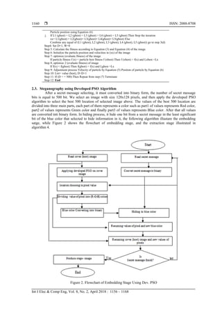
PSO search space which produces the best locations or positions. The developed PSO algorithm for finding
best position is shown in algorithm (2). for an iteration process of the algorithm, if better solution is satisfied,
then the global best position and the best local position are modified or updated. This process is continuous
until the determined number of iterations is exhausted. In this work, The number of iterations is 500
iteration[8].
Algorithm 2. Developed PSO Algorithm
Input : 128*128 cover image , parameters α , β,rand1, rand2, max iteration D, variable W, best
location xx,(L1,L2,L3,L4,L5)=particles
Output: Selected locations
Begin
Step 1: Set D=1, W=0
Step 2: Position fitness is computed using Equatin (3) and Equation (4)
Step 3: For the selected image do the following
a. Divided the image region into five section
b. Specify the center of each section
c. Initialize the five particle position and velocities in center of each section
d. Determine the fitness of gbest for each particle
e. Choose the best of them
f. Optimize (evaluate fitness) to the better
g. If the particle fitness f (x) < particle best fitness f (xbest) Then f (xbest) = f(x) and Lxbest =Lx
h. If f(x) < f (gbest) Then f (gbest) = f(x) and L (gbest) =Lx
i. Update
Particle velocity using Equation (5)](https://image.slidesharecdn.com/v587oct1728jul8110-10804-1-ed-201110085336/85/Information-Hiding-using-LSB-Technique-based-on-Developed-PSO-Algorithm-4-320.jpg)


![ ISSN: 2088-8708
Int J Elec & Comp Eng, Vol. 8, No. 2, April 2018 : 1156 – 1168
1168
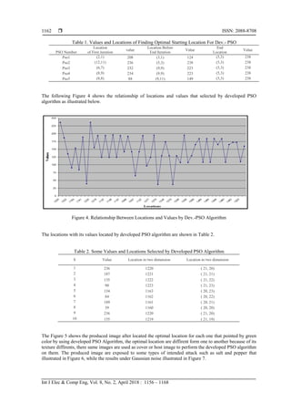
information missing, this result indicates to level of accuracy in selecting the best location, also the selected
locations are almost serially, and this give us pointer that the developed PSO algorithm is fast. If the bird has
predetermined for starting point then all birds follows it, patchwork technique used in the proposed method to
hide a secret message inside the cover image in spatial domain in the three color sub-band at the same time to
make abel to survive the stego image from intended or un-intended attack, therefore if one of an sub-band
distroed, the secret message can be extracted from other sub-ban. Our proposed method take three samples
during the testing process and take into consideration image texture, and the diffirents results that tabled
shows that the proposd method has ability to hide a secret message inside the cover image under spatial
domain by using LSB technique (LSB substitution).
REFERENCES
[1] Nidhi Sethi and Sandip Vijay, "A New Cryptographic Strategy for Digital Images", International Journal of
Electrical and Computer Engineering (IJECE), Vol. 4, No. 3, pp. 456~462, June 2014.
[2] P. Kumar and V. K. Sharma, "Information security based on steganographyand cryptography techniques: A review"
International Journal of Advanced Research in Computer Science and Software Engineering, Volume 4,
Issue 10, October 2014.
[3] R. Gupta, S. Gupta, and A. Singhal, "Importance and techniques of Information Hiding," International Journal of
Computer Trend and Technolog (IJCTT) - volume 9 number 5- Mar 2014
[4] T. Morkel, J.H.P Eloff and M. S. Olivier, "An Overview of Image Steganoghraphy” Information and Computer
Security Architecture (ICSA), Research Group, Department of Computer Science, University of Pretoria, 0002,
Pretoria, South Africa.
[5] M. Junej, P.S. Sandhu, “Improved information security using Steganography and Image Segmentation during
transmission”, Computer Science and Engineering Department, Rayat and Bahra Institute of Engineering and
Technology (RBIEBT), Sahauran (Punjab), India
[6] D. Bhowmik,”Robust Watermarking Techniques For Scalable Coded Image And Video”, PhD thesis, Department
of Electronic and Electrical Engineering, The University of Sheffield, p.13-34, 2010.
[7] S. Patel, A. Katharotiya, M. Goyani,”A Survey on Digital Video Watermarking”, IJCTA | NOV-DEC 2011.
[8] Champakamala B.S, Padmini. K, Radhika D.K., ”Least Significant Bit algorithm for image steganography”,
International Journal of Advanced Computer Technology (IJACT), Department of TCE, Don Bosco Institute of
Technology, Bangalore, India,ISSN:2319-7900
[9] Chang CC, Chan CS, Fan YH. Image hiding scheme with modulus function and dynamic programming strategy on
partitioned pixels. Pattern Recognit 2006;39:1155–213.
[10] Bajaj R, Bedi P, Pal SK. “Best hiding capacity scheme for variable length messages using particle swarm
optimization” In: Proc SEMCCO 2010. LNCS 6466. p. 237–44.
[11] Bedi P, Bansal R, Sehgal P, “Using PSO in image hiding scheme based on LSB substitution”, In: Proc international
conference on advances in computing and communications (ACC 2011); CCIS 192; 2011. p. 259–68.
[12] Kennedy J. and Eberhart R. C., "Particle Swarm Optimization", Proceedings of the 1995 IEEE International
Conference on Neural Networks, volume 4, PP: 1942–1948, Australia, IEEE Service Center, 1995.
[13] N. Ramesh Raju and P. Linga Reddy, "Robustness Study of Fractional Order PID Controller Optimized by Particle
Swarm Optimization in AVR System", International Journal of Electrical and Computer Engineering (IJECE),
Vol. 6, No. 5, pp. 2033~2040, October 2016.
[14] Ismail Khalil Ali, "Intelligent Cryptanalysis Tool Using Particle Swarm Optimization", Ph.D. Thesis, University of
Technology, Department of Computer Science, 2009.
[15] Nor Azlina Ab Aziz, Zuwairie Ibrahim, Marizan Mubin, Sophan Wahyudi Nawawi and Nor Hidayati Abdul Aziz,
"Transitional Particle Swarm Optimization", International Journal of Electrical and Computer Engineering
(IJECE), Vol. 7, No. 3, pp. 1611~1619, June 2017.](https://image.slidesharecdn.com/v587oct1728jul8110-10804-1-ed-201110085336/85/Information-Hiding-using-LSB-Technique-based-on-Developed-PSO-Algorithm-13-320.jpg)