Industrial training report- Visakhapatnam Steel Plant.
1. 1
Observation of different processes in Steel Making at
Vishakhapatnam Steel Plant
Period of Observation- May 27th,2013 to June22nd, 2013
Abstracts
A steel plantis an industrial plant for the manufacture of steel. We had done an in-plant industrial
trainingat VishakhapatnamSteel Planton“Observationof different processesin Steel Making”. The
purpose of the training was to know about raw material handling, coke preparation, Sintering
Process, working of Blast Furnace, working of Basic Oxygen Furnace and rolling of different mill
products. We also gathered thorough knowledge about maintenance and spares and working
principle of different material handling systems and equipments in Steel Making.
Introduction
Steel is an alloy of iron and carbon containing less than 2% carbon and 1% manganese and small
amountsof silicon,phosphorus,sulphurandoxygen.Steelisthe world'smostimportantengineering
and construction material. It is used in every aspect of our lives; in cars and construction products,
refrigeratorsandwashing machines, cargo ships and surgical scalpels. Steel is not a single product.
There are more than 3500 different grades of steel with many different physical and chemical
properties.
Steel isveryfriendlytothe environment.Itiscompletelyrecyclable, possesses great durability, and
compared to other materials, requires relatively low amounts of energy to produce. Innovative
lightweightsteelconstruction suchasinautomobile andrail vehicle construction helptosave energy
and resources.The steel industryhasmade immenseeffortstolimit environmental pollution in the
lastdecades.Energyconsumptionandcarbondioxide emissionshave decreasedtohalf of what they
were in the past decades.
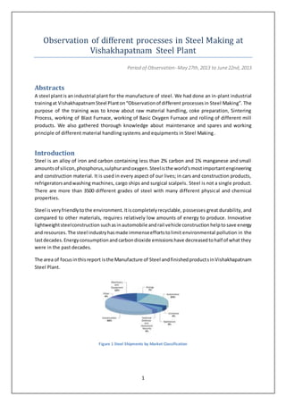
The area of focusinthisreport isthe Manufacture of Steel andfinishedproductsinVishakhapatnam
Steel Plant.
Figure 1 Steel Shipments by Market Classification
2. 2
Company Profile
VisakhapatnamSteelPlant,popularlyknownas VizagSteel,hereafter referred to as VSP is the most
advanced Indiangovernment-ownedsteel producer. It is an Integrated Steel Plant. It produces one
of the best products in the world market. Most of its income comes from the exports of steel
products to Japan, Germany, United States, Singapore, Dubai, Australia, South American countries
and many more. Vizag Steel Plant has been conferred Navratna status on November 17th
, 2010.
Founded in 1971, the company focuses on producing value-added steel.
Equippedwithmoderntechnologies,VSP has an installed capacity of 3 million Tonnes per anum of
liquidsteeland2.656 millionTonnesof saleablesteel.AtVSPthere isemphasisontotal automation,
seamless integration and efficient upgradation which result in wide range of long and structural
products to meet the stringent demands of discerning customers within India and abroad. VSP
Products meet exalting International Quality Standards such as JIS, DIN, BIS, BS etc.
VSPhas manymajor productionfacilitiessuchas3 coke oven batteries of 67 oven each having 41.6
cubic meters volume, 2 Sinter machines of 312 square meters area, 3 Blast furnace of 3200 cubic
metersof useful volume, Steel Melt Shop with 3 L.D. converters of 150 Tonnes capacity each, six 4
strand continuous bloom casters, Light and Medium Merchant Mill of 710,000 Tonnes per year
capacity, Wire rod mill of 850,000 Tonnes per year capacity, Medium Merchant & Structural Mill of
850,000 Tonnes per year capacity.
Extensive facilitieshave beenprovided for repair and maintenance as well as manufacture of spare
parts. A Thermal Power Plant and an Air Separation Plant also form part of the plant facilities.
Moderntechnologyhasbeenadoptedinmany areas of production, some of them for the first time
inthe country.Among these are Selective crushing of coal, Pneumatic Separation of Coal, 7 meter
tall coke ovens, Dry quenching of coke, on-ground blending of Sinter base-mix, conveyor charging
and bell less top for blast furnace, cast house slag granulation for blast furnace, gas expansion
turbine forpowergeneration utilizing blast furnace top gas pressure, hot metal de-sulphurization,
extensive treatment facilities of effluents for ensuring proper environmental protection,
computerization for process control and sophistication in high speed and high production rolling
mills.
Training Work
Raw Material Handling Plant
Raw Material Handling Plant hereafter referred to as RMHP deals with the incoming and basic
processing of raw materials in VSP. It is broadly divided into two departments
Ore Handling Plant (OHP)
Coal Handling Plant (CHP)
The Ore Handling Plant hereafter referred to as OHP deals with the iron ore and flux material as
limestoneanddolomite.The Coal HandlingPlanthereafterreferred to as CHP deals with coking and
non-coking coal. The major sources of raw material are-
3. 3
Raw Material Source
Iron Ore Lumps and Fines Bailadilla, Madhya Pradesh
Blast Furnace Limestone Jaggayyapeta, Andhra Pradesh
Steel Melting Shop Limestone United Arab Emirates
Blast Furnace Dolomite Madharam, Andhra Pradesh
Steel Melting Shop Dolomite Madharam, Andhra Pradesh
Manganese Ore Chipurupalli, Andhra Pradesh
Boiler Coal Talcher, Odisha
Coking Coal Australia
Medium Coking Coal Gidi, Swang, Rajarappa, Kargali
Iron ore,flux material and coal are classified into Lump, Sized or fines according to the sizes. If the
size ismore than 40mm thenit isa lump,if less than 10mm then fine or if between 10mm to 40mm
thensized.Basicallysizedore andcoke are required forblast furnace. The material are measured in
terms of sieve sizes only. The major features of RMHP are-
Wagon Tipplers
Raw material like iron ore, limestone and coal are supplied to VSP from the mines by the Indian
Railwaysthroughrakeswhichconsist of 51 to 58 wagons.The rotary tipplersdesigned for unloading
of broad-gauge open railway wagons by inverting the wagons by maximum up to 175o
thereby
discharging its contents into the hoppers below the rail. The operating angle is kept at 165o
. The
tipplers are designed to handle wagons having a gross load up to 110 Tonnes. The ideal tippler
working cycle is 60 seconds which means that the ideal rake retention time should be around 3
hours but it actually takes around 8 to 9 hours.
The ore, flux andthe coal fall intobunkerswhichfeedthe material toapronfeederswhichare metal
beltconveyorsdesigned to take the load of the bulk material. Next the material are conveyed to a
shuttle conveyor which in turn distributes the material uniformly into different conveyors. Finally
these are carried to the stockyard.
Figure 2 (a) Wagon Tippler at 45O (b) Rack and Pinion Mechanism (c) Drive Unit
4. 4
Figure 3 (a) Rake in Pre-Tippling Track (b) In-Haul Car
WorkingPrinciple
The tippler consists of 3 circular rings, a platform with travel rails, support rollers as well as a
clamping device which retain wagons from top and side during tippling. It is driven by a drive unit
located on one side of the tippler. The drive unit consists of a motor, flexible couplings, thruster
operated brakes, helical gear-box, pinion and toothed rings.
The wagonsare placedon the pre-tippler with the help of Pusher cars. The wagons are de-coupled
from the rake manually and pushed by the Pusher car into the tippler platform.
The tippler rotates by a small angle till sides of the wagons are clamped to the side wall of the
tippler. On further rotation the platform moves in a way such that the wagons get clamped at the
top also ensuring rotation up to 175o
all by the virtue of their own weights only. After discharging
the bulkmaterial the wagonsare broughtback to initial position bythe tipplerandpushedbyPusher
cars to the rake storage area.
The principle of working is called Rotary Gravity Clamping Mechanism.
Figure 4 Wagon Tippler Working Mechanism
5. 5
Ground and Track Hoppers
These are basically railroad freight cars used to transport loose flux material such as limestone,
quartz,dolomite andsandintoVSP. These are dumped manually into bunkers and the material are
sent to the stockyard with the help of conveyors. The hoppers are used either when the use of
wagon tipplers is not economical or there is a possibility of wagon getting damaged.
Figure 5 Hopper Car
Stockyard Systems
The central function of stockyards in the field of bulk materials handling lies in the buffering,
blending and storage between incoming and outgoing materials.
The stockyard systems include stackers and reclaimers and some stacker cum reclaimers. In VSP
there are 3 stackers, 3 reclaimers, and 4 stacker-cum-reclaimers.
A stackeris a large machine usedinbulkmaterial handling. Its function is to pile bulk material such
as limestone, coal and iron ore into stockpile. A reclaimer is used to remove the material from the
stockyard. The stacking rate in VSP is 750 Tonners per hour and the reclaiming rate is 550 Tonners
per hour.
The other features of a stockyard system are travelling unloader and feed table which are used in
stacking and reclaiming respectively. In case of stacker cum reclaimers both are used.
A travellingcarisalsousedto move the machinestoany track fromany track overthe entire area of
the stockyard.A strapper is used in each reclaiming chute to strap off sticky material from the yard
conveyors.
The machineshave three basicmotionsviz.longitudinal travel,slewing i.e. lateral movement of arm
and luffingi.e. vertical movementof arm.The majordrive mechanismare longitudinal drive, slewing
drive, luffing drive, boom conveyors, bucket wheel drive, power cable reeling drive etc. In boom
conveyors garlanding idlers are used for shock absorption.
6. 6
Figure 6 (a) Feed Table with Conveyor (b) Travelling Unloader (c) SCR during Reclaiming (d) Stacker Working
Lump Ore Screening Plants
In thisplant lump iron ore and flux material like limestone are screened. The screening is done on
the basis of screen mat sizes only.
There are two primary vibrating screens and 3 secondary vibrating screens. The primary vibrating
screens have a capacity to screen 350 Tonnes to 450 Tonnes per Hour and are the drive mechanism
islubricatedbyoil.The secondaryvibratingscreens have a capacity to screen 200 to 250 Tonnes per
hour and the drive mechanism is lubricated by grease.
The Screens have an exciter system and vibration amplifier springs to ensure better flow of bulk
material.Flywheelsare providedformaintaininginertia.The vibrationfrequencyis maintained with
the help of Stroke Measurement Diagrams. In VSP the standard reading is 10.
7. 7
Figure 7 (a) Primary Vibrating Screen (Top) (b) Vibro Feeder (c) Vibrating mechanism of Secondary Vibrating Screen (d)
Stroke Measurement Diagram (e) Lumps getting Screened (f) Flywheels of Primary Vibrating Screen
Working Principle
Lump ore and flux material are firstscreenedinthe primaryvibratingscreens.The sizedmaterialand
fines pass through the screening mats and are sent back to the stockyard. The lumps which are
screened are sent to crushers which are again screened in the secondary vibrating screens. The
processisrepeateduntil the materials are converted to the optimum size i.e. less than 40mm size.
Crushing Plant
There are twotypesof CrushingplantsinVSPnamelythe Non Coking Coal Crushing Plant and Lump
Ore Crushing Plant.
Non Coking Coal Crushing Plant
In the coal crushing plant the boiler coal are crushed into sizes less than 25mm in Ring Granulators
and are supplied to the Thermal Power Plant. As coal is soft material Ring Granulators are used.
InitiallyinRingGranulatorsScoopControlledFluidCouplingUnitwere usedbut due to maintenance
problems nowadays Delayed Chamber Fluid Coupling Units are used.
The machine comprises screen plate or cage bar steel box with an opening for the introduction of
material tobe crushedset to one side inthe topcover.A slopingbreakerplate arrangedon a hinged
8. 8
cage frame issetto one side of the feedentryanda power driven horizontal mainshaft passes from
frame side to frame side parallel to this breaker plate.
The main shaft carried in the roller bearings from the box sides support a number of circular disks
fixed at regular intervals across its length within the frame. A series of bars running parallel to the
main shaft pass through these disks near the outer edges. The bars are equally spaced about the
main shaft center and carry a series of rings which are free to turn on the bars irrespective of the
main shaft rotation. Below the rotor assembly the movable cage frame is carried round at a radius
marginally larger that of the ring running periphery.
Figure 8 Ring Granulator being sent for Repairing
Working Principle of Ring Granulators
The crushing action is performed when material is dropped through the feed opening where it is
struck in mid air by multiple rings which are being driven round by the rotor discs in direction
towards the breaker plate. The ring are mounted on suspension bars. When the rotor is set in
motion centrifugal force brings the ring out against material to be crushed.
As material is fed to the machine the rings are forced back towards the rotor centre until bar is
encountered by the ring internal surface and a forward driving force is exerted. The material is
brokenanddischargedthroughthe cage barsor screen platesthuseasing the load and allowing the
ringto move out until itis heldonce againby suspensionbarbefore encounteringthe incomingfeed
once again.
The ring are thusheldindeepcontactwiththe bedof material onthe cage bars or screenplates and
theyrevolve with planet like motion relative to the direction of rotor rotation. This rolling feature
provides a constant effective crushing action which in turn ensures a granular material size.
9. 9
Figure 9 Working Principle of Ring Granulator
Lump Ore Crushing Plant
In LumpOre Crushingplanthard bulk material suchas ironore andflux are crushedin GyratoryCone
Crushers.2 pumpsare usedtosupplylubricatingoil to the driving mechanism. The flow rate of this
oil is maintained at 70 liters per minute in both input and output pipes. Heat exchangers are also
installed for maintaining the oil temperature.
The major parts of the crushersare motor,pinionor countershaftbevel gear,socketassembly,cone
assembly, bowl assembly, feed arrangement and chute. The Cone Assembly consists of Lower
Mantle, Square box, half rings, wedges and feed plate. Manganese lining is used on lower mantle
and bowl lining i.e. the crushing surfaces to provide hardness. Backing material ore used between
the mainframe and reverse surfaces of lower mantle and bowl lining for shock absorption.
10. 10
Figure 10 (a) Layers of Crushing Plate (b) Oil Pump (c) Squirrel Cage Induction Motor (d) Shock Absorbing Springs (e)
Cone Crusher Internal View (f) Cone Crusher External View
Working Principle of Gyratory Cone Crusher
A cone crusher breaks ore and flux lumps by squeezing the material between an eccentrically
gyrating spindle, which is covered by a wear resistant mantle, and the enclosing concave hopper,
coveredby a manganese concave or a bowl liner. As material enters the top of the cone crusher, it
becomeswedgedandsqueezedbetweenthe mantle and the bowl liner or concave. Large pieces of
ore are brokenonce,andthenfall to a lowerposition(because theyare now smaller) where theyare
broken again. This process continues until the pieces are small enough to fall through the narrow
opening at the bottom of the crusher.
A cone crusher is suitable for crushing a variety of mid-hard and above mid-hard ores and flux
material.Ithas the advantage of reliable construction,highproductivity,easyadjustment and lower
operational costs. The spring release system of a cone crusher acts an overload protection that
allows tramp to pass through the crushing chamber without damage to the crusher.
11. 11
After crushing the ore and flux are sent to the Sinter Plant and Blast Furnace.
Figure 11 (a) Parts of a Cone Crusher (b) Crushing Mechanism (c) Cone Crusher Schematic
Spontaneous Combustion of Coal
Self Ignitionof coal isan exothermicchemical reactionandasubsequent rise in temperature occurs
inthe combustiblematerial without the action of an additional source. Self ignition is supposed to
occur when the thermal equilibrium between the two counteracting effects of heat release by
oxidation reaction and heat loss due to heat transfer to ambience is disturbed. When the rate of
heat produced exceeds the heat lost, a temperature rise within the material consequently takes
place.
12. 12
In VSP,more than 40% of the total non coking coal kept in the stockyard gets exhausted due to the
self-combustion.
Figure 12 (a) & (b) Spontaneous Combustion of Coal
Explanation and Reactions
Spontaneous combustion of coal is initiated by oxidation of coal. Coal fire requires the basic
elements to exist.
Oxidation occurs when the Oxygen reacts with the fuel i.e. coal. It produces heat. At a high
temperature,oxidationreactionproceedsata highrate.Eventuallyatemperature is reached where
the ignition of the material occurs.
The complete oxidation of Carbon to Carbon dioxide in an exothermic reaction that leads to heat
emission between 21 to 42 Kilo Joule per gram of coal , taking into consideration, that coal is
composed of pure Carbon. The reactions occurring are-
𝐶 + 𝑂2 → 𝐶𝑂2 + 394 𝐾𝐽 𝑚𝑜𝑙𝑒⁄
2𝐶 + 𝑂2 → 2𝐶𝑂 + 170 𝐾𝐽 𝑚𝑜𝑙𝑒⁄
2𝐻2 + 𝑂2 → 𝐻2 𝑂 + 241𝐾𝐽 ⁄ 𝑚𝑜𝑙𝑒
Self Sustained Combustion
200o
C-250o
C
Thermal Decomposition
180o
C-250o
C
Slow Oxidation
upto 50o
C
Steady State Oxidation
between 50o
C -80o
C
Evolution Of Oxides Of Carbon
upto 120o
C
Rapid Interaction with O2
upto 180o
C
Slow Oxidation
upto 50oC
Coal + O2 (Input)
13. 13
Coke Ovens and Coal Chemical Plant
The most commonsteel makingtechnologyisthe BlastFurnace – Basic OxygenFurnace Route. Coke
is used in Blast Furnace hereafter referred to as BF as a reductant as well as a source of thermal
energy.Itinvolvesreduction of ore to liquid metal in the blast furnace and refining in convertor to
form steel. The various stages of the steel plant are described below.
Figure 13 Layout of CO & CCP
Coal PreparationPlant
The Coal PreparationPlanthereafterreferredtoasCPPdealswiththe processing&storage of
differentgradesof coal and itsdispatchto the Coke ovenbatteriesasandwhenneeded.InVSPcoal
of differentgradesiscollectedfromthe storage yardusingreclaimersandfeedtable.Thiscoal is
storedin16 large storage binsaccordingto theirgrades.Coal storedinthese binsisthencombined
indifferentproportionstoproduce cokingcoal havingoptimumcomposition.Thismixtureisthen
sentthroughrollercrusherto produce coal of size lessthan3mmwhichis thensentto the coke
ovenbattery.
Crushing Section
In the crushing section roll crushers are used. These can be referred to as compression-type
crushers.The RollerCrusherincorporates one Stationary Roll and one Moveable Roll. The Movable
Roll providesrelief bymovingawayfrom the StationaryRoll when rigidmaterial is encountered and
immediately resets to the original position. Roll diameters range from 457.2mm to 1930.4mm and
roll widths up to 3048mm.
14. 14
Figure 14 (a) Coal Bunker Discharge Cone (b) Coal Storage Bin
Roll crusher has the advantage of producing an end-product that is has a fine size distribution and
they produce little dust or fines during operation. It is widely used for crushing minerals whose
abrasive levels are low and in the small scale production of mine. Roll crushers are mostly used
during coal mining. The crushers used may either be single roll or double roll. When used in coal
mining,the surface of the rollswill have teethorraisedforms whenusedformineralandmetal ores,
the rolls have a smooth surface.
Battery of Coke Ovens
There are 4 Coke Oven Batteries, 7 meters tall and having 67 ovens each. Each oven is having a
volume of 41.6 Cu. M and can hold up to 31.6 Tonnes of dry coal charge. The carbonization takes
place between 1000o
C and1050o
C in absence of air for 16 hours to 18 hours.
Coke Oven Machines
The following oven machines are under operation at top charged battery.
Charging car- It operates on the top of the ovens and discharges crushed coal in the
oven.
Pusher car- Coke pusher is designed for pushing coke out of coke ovens. The machine
carriesout mainoperations:coke ovendoor extraction, pushing coke out of coke oven,
leveling of coal-charge. The machine is equipped with a mechanism that fulfills main
operation like burning graphite on coke oven roof, cleaning and service of doors or
frames, raising, lowering, cleaning of leveler hatch, receipt, storage, discharge of coal
spilled when leveling and spillage cleaning.
Guide Car- It operatesonthe coke side of the battery.It opensthe coke side doorguides
the hot coke into the quenching car followed by closing the coke-side door.
Quenching Car- Receives the hot coke and takes it to the quenching station for water
quenching.
15. 15
Figure 15 (a) Pusher Car (b) Coal Discharge Car (c) Coke Oven (d) Coke Oven Gas
Coke Making (Coal Carburization)
Cokingcoalsare the coalswhichwhenheatedinthe absence of air,firstmelt,go in the plastic state,
swell and resolidify to produce a solid coherent mass called coke. When coking coal is heated in
absence of air,a seriesof physical andchemical changes take place with the evolution of gases and
vapors, and the solid residue left behind is called coke.
Conventional coke making is done in a coke oven battery of ovens sandwiched between heating
walls. They are carbonized at a temperature around 1000o
-1100o
C up to a certain degree of de-
volatizationtoproduce metallurgical coke of desired mechanical and thermo-chemical properties.
During carbonization, coking coals undergo transformation into plastic state at around 350o
C to
400o
C, swell and then solidify at around 500o
C to 550o
C to give semi-coke and then coke. In coke
ovens,aftercoal ischarged inside the oven,plastic layers are formed adjacent to the heating walls,
and withthe progress of time, the plastic layers move towards the centre of oven from either side
and ultimately meet each other at the centre. During coke making, two opposite reactions take
place. These reactions are namely condensation and pyrolysis. The quality and quantity of plastic
layer is of extreme importance and it determines the inherent strength of coke matrix.
16. 16
Coke Dry Quenching Plant
Coke dry quenching appears as the most valid system to reduce air pollution allowing at the same
time a remarkable energyrecoveryorsaving,especiallywhenitisassociatedwithcoal preheating.In
addition, dry quenched coke is harder and stronger, and its moisture content is much lower than
that of wet quenched coke.
The coke dry quenching equipment broadly consists of a coke cooling tower (pre-chamber and
cooling chamber) and a waste heat recovery boiler. Red-hot coke approximately at a temperature
1200°C ischarged intothe coke coolingtower and liquid Nitrogen is blown into the tower from the
bottom. Heat exchange is performed with the circulating Nitrogen. After the gas is heated to high
temperature approximately up to 800°C it circulates through the heating tubes of the waste heat
boiler, converting the water in the boiler into steam. The temperature of the coke at the cooling
tower outlet is reduced to approximately 200°C.
During this process, the heated coke passes the middle part of a chamber wherein a flow of a gas-
steam mixture heated to a temperature of up to 700°C is introduced in countercurrent relation to
the flowof coke.Resulting from the process of conversion of hydrocarbons with water vapor is gas
containinghydrogen andcarbonmonoxide.The blast furnace coke with a temperature of not lower
than 700°C is passed froma middle partof the chamber to a lower part thereof wherein it is cooled
to a temperature of 200°C to 250°C with a flow of circulating Nitrogen.
At VSPthere are 4 Coke Dry QuenchingPlantseachhaving 4 cooling chambers. The capacity of each
cooling chamber is 50 Tonnes per Hour 52 Tonnes per Hour. The heat recovery from Nitrogen is
done by generating steam and expanding in two back pressure turbines to produce 7.5 Megawatt
power each.
Coke Coal and Chemical Plant
The coke oven by-product plant is an integral part of the by-product coke making process. In the
processof convertingcoal intocoke usingthe by-productcoke oven,the volatilematterinthe coal is
vaporizedanddrivenoff.Thisvolatile matterleaves the coke oven chambers as hot, raw coke oven
gas. Afterleavingthe coke ovenchambers,the raw coke oven gas is cooled which results in a liquid
condensate stream and a gas stream. The functions of the by-product plant are to take these two
streamsfromthe coke ovens,toprocessthemto recoverby-productcoal chemicalsandtocondition
the gas so that it can be used as a fuel gas.
Composition of the Coke Oven Gas
Raw coke oven gas coming from the coke oven battery has the following typical composition:
Dry Basis Actual Composition
(Water saturated)
Water Vapor - 47%
Hydrogen 55% 29%
Methane 25% 13%
Nitrogen 10% 5%
Carbon Monoxide 6% 3%
Carbon Dioxide 3% 2%
Hydrocarbons (Ethane, Propane etc) 2% 1%
17. 17
In addition to treating the coke oven gas, the by-product plant must also condition the flushing
liquorthatis returnedtothe coke oven battery, and treat the waste water that is generated by the
coke making process.
Figure 16 (a) Benzol Distillation Plant (b) Tar & Liquor Plant
Stream Destination
Coke Oven Gas Used as fuel gas at the coke oven battery and in
steel works
Flushing Liquor Re-circulated to the Coke oven battery
Waste Water Discharged to treatment plant
Tar Sold as Product
Ammonia or Ammonium Sulphate Sold as Product
Light Oil Sold as Product
Blast Furnace
At the top of the furnace the materials are held until a charge usually consisting of some type of
metallic ore, pellets or sinter, coke and flux like limestone have accumulated. The precise filling
order is developed by the blast furnace operators to carefully control gas flow and chemical
reactions inside the furnace.
The materialsare charged into the blast furnace through 2 or 3 airlock type hoppers that discharge
raw materials onto a rotating chute which can change angles allowing more flexibility in precise
material placementinsidethe furnace.Thisisknownas the Paul Wurth bell-less charging system, it
offers the following advantages:
Improved furnace operational stability & efficiency leading to better hot metal chemistry
control;
Increased furnace productivity;
Loweroperatingcoststhanksto reducedcoke consumptionand higher attainable PCI rates;
Longer campaign life thanks to reduced blast furnace wall heat loads;
Limited equipment maintenance, easy and quick maintainability.
Another product of the iron making process, in addition to molten iron and slag, is hot dirty gases
referred toas BlastFurnace gas or BF Gas. These gasesexitthe topof the blast furnace and proceed
through gas cleaning equipment where particulate matter is removed from the gas and the gas is
18. 18
cooled.Thisgashas a considerable energyvalue so itisburnedasa fuel inthe hotblaststoves which
are used to preheat the air entering the blast furnace to become hot blast. Any of the gas not
burned in the stoves is sent to the boiler house and is used to generate steam which turns a turbo
blower that generates the compressed air known as cold blast that comes to the stoves.
The hot blastmainentersintoa doughnut shaped pipe that encircles the furnace, called the bustle
pipe.Fromthe bustle pipe,the hotblastisdirectedintothe furnace through nozzles called tuyeres.
These tuyeresare equallyspaced around the circumference of the furnace. There are 32 tuyeres in
VSP BF Godavari. These tuyeres are made of copper and are water cooled since the temperature
directlyinfrontof themmay be 3600o
F to 4200o
F. The moltenironandslag drippastthe tuyeres on
the way to the furnace hearth which starts immediately below tuyere level.
Figure 17 (a) HM Ladle Car (b) Bustle Pipe (c) Tuyeres (d) Rice Husk for Insulation
19. 19
Figure 18 (a) Layout of Charging System (b) Molten Metal from tap Hole (c) Molten Metal in Torpedo Ladle
Aroundthe bottom half of the blastfurnace the cast house enclosesthe bustlepipe,tuyeresand the
equipment for casting the liquid iron and slag. The opening in the furnace hearth for casting or
drainingthe furnace iscalledthe iron notch. A large drill mounted on a pivoting base called the tap
hole drill swingsuptothe ironnotch and drillsahole throughthe refractoryclay plug into the liquid
iron. Another opening on the furnace called the cinder notch is used to draw off slag or iron in
emergencysituations.Once the taphole isdrilledopen,liquidironandslagflow downadeeptrench
called a trough.
The liquid iron flows through the trough into refractory lined ladles known as torpedo cars or sub
cars due to theirshape.Whenthe liquidsinthe furnace are draineddownto tap hole level, some of
20. 20
the blast from the tuyeres causes the tap hole to spit. This signals the end of the cast, so the mud
gun is swung into the iron notch. The mud gun cylinder, which was previously filled with packs of
Bauxite based clay, is actuated and the cylinder ram pushes clay into the iron notch stopping the
flow of liquids. When the cast is complete, the iron ladles are taken to Steel Melting Shop for
processing into steel and the slag is taken to the Slag Granulation Plant where it is processed. The
cast house isthencleanedand prepared forthe nextcast whichoccurs in40 minutesto 45 minutes.
It isimportantto cast the furnace at the same rate that raw materials are charged and iron and slag
producedsoliquidlevelscanbe maintainedinthe hearthandbelow the tuyeres.Liquidlevelsabove
the tuyeres can burn the copper casting and damage the furnace lining.
Working of Blast Furnace
All of the raw materialsare storedinan ore fieldandtransferredtothe stockhouse before charging.
Once these materials are charged into the furnace top, they go through numerous chemical and
physical reactions while descending to the bottom of the furnace.
The iron ore, pellets and sinter are reduced which simply means the oxygen in the iron oxides is
removed by a series of chemical reactions. These reactions occur as follows-
At the same time the ironoxidesare goingthroughthese purifyingreactions,theyare alsobeginning
to softenthenmelt and finally trickle as liquid iron through the coke to the bottom of the furnace.
The coke descends to the bottom of the furnace to the level where the preheated air or hot blast
enters the blast furnace. The coke is ignited by this hot blast and immediately reacts to generate
heat.
𝐶 + 𝑂2 → 𝐶𝑂2 + 𝐻𝑒𝑎𝑡
Since the reaction takes place in the presence of excess carbon at a high temperature the carbon
dioxide is reduced to carbon monoxide.
𝐶𝑂2 + 𝐶 → 2𝐶𝑂
The product of this reaction, carbon monoxide, is necessary to reduce the iron ore as seen in the
previous iron oxide reactions.
The limestone descends in the blast furnace and remains a solid while going through its first
reaction.
𝐶𝑎𝐶𝑂3 → 𝐶𝑎𝑂 + 𝐶𝑂2
Thisreactionrequiresenergyand starts at about 1600o
F. The CaO formed from this reaction is used
to remove sulphur from the iron which is necessary before the hot metal becomes steel. This
sulphur removing reaction is:
𝐹𝑒𝑆 + 𝐶𝑎𝑂 + 𝐶 → 𝐶𝑎𝑆 + 𝐹𝑒𝑂 + 𝐶𝑂
The CaS becomespart of the slag.The slagis also formed from any remaining Silica (SiO2), Alumina
(Al2O3),Magnesia(MgO) or Calcia(CaO) that entered with the iron ore, pellets, sinter or coke. The
liquidslagthentricklesthrough the coke bed to the bottom of the furnace where it floats on top of
the liquid iron since it is less dense.
21. 21
Precisely the blast furnace is a counter-current realtor where solids descend and gases ascend. In
this reactor there are numerous chemical and physical reactions that produce the desired final
product which is hot metal.
Figure 19 BF Schematic Diagram
Slag Granulation
The slag fromthe BF is sentto the SlagGranulationPlant.The RedHot moltenslagischargedwith
chilledwaterandslagbeingbrittle material directlygetsquenchedandgranulated.The granulated
slagis soldto differentCementFactories.
Utilization of Blast Furnace Gas
Blast furnace gas is a by-product of blast furnaces that is generated when the iron ore is reduced
with coke to metallic iron. It has a very low heating value, about 93 BTU per cubic foot, because it
consists of about 60% nitrogen, 18% to 20% carbon dioxide and some oxygen, which are not
flammable. The rest is mostly carbon monoxide, which has a fairly low heating value already. It is
commonlyusedasa fuel as a fuel inthe hot blast stoves which are used to preheat the air entering
the blastfurnace to become hotblast.It may be combinedwith natural gas or coke oven gas before
combustion or a flame support with richer gas or oil is provided to sustain combustion. Particulate
matter is removed so that it can be burned more cleanly.
BF Gas is generated at higher pressure. This pressure is utilized to operate a generator, Top Gas
Pressure Recovery Turbine hereafter referred to as TRT which can generate electrical energy up to
22. 22
35 Kilowatt-hour per Tonne of pig iron without burning any fuel. Dry type TRTs can generate more
power than wet type TRT.
Steel Melting Shop
In Steel Melting Shop of VSP hereafter referred to as SMS, LD Process of steel making has been
adopted.The liquidsteel obtained from LD process is cast into blooms through Continuous Casting
Machines or Bloom Casters. SMS is divided into two major sections.
Converter Shop
Continuous Casting Shop.
The Converter shop has the following sections.
Bulk Material Handing Section
Mixer Shop
Converter Bay
Scrap Yard
Slag Yard
Ladle PreparationBay
The Continuous Casting Shop has the following sections.
Tundish preparation Bay
Argon Rinsing Station
Continuous Casting Machines
Gas Cutting Machines
BloomStorage Yard
MixerShop
It isverydifficulttosupplythe hotmetal fromBlastFurnace to the converter as per its requirement
unless there is an arrangement for storing the hot metal in SMS. Mixer serves this purpose. There
are two mixers in SMS. The Capacity of each mixer is 1300 Tonnes of Hot Metal. In mixer,
temperature of hot metal is maintained by burning coke oven gas with air. The Mixer vessel is in
cylindrical form with two removable spherical ends. Length of the vessel is 10.67 meters and
diameteris7.64 meters.The mixerisinstalledonamixerplatformand is served by 2 mixer crane of
capacity 180T/63T/20T. The main units of the mixer are shell assembly, roller support, tilting
mechanism,handbrake mechanism, chargingholecover winch, charging hole platform, spout door
opening mechanism, gas & air distribution system, installation of blower, lubrication system etc.
23. 23
Figure 20 (a) Hot Metal Stored in Mixer (b) Mixer
Converter Bay
Hot metal containsdifferentimpurities like Carbon(C),Silicon(Si), Manganese(Mn), Sulphur(S), and
Phosphorus(P)above safe level whichmake PigIronbrittle.Typical hotmetal compositionisC (3.5 %
to 4.25%), Si (0.4% to 0.5%), Mn (0.3% to 0.4%), S (0.04% max) and P (0.14% max). Steel is nothing
but refinedhotmetal.Refiningisonlypossiblewhenthingsare inmoltenphase.Refining is done by
blowing oxygen in the LD converter or Basic Oxygen Furnace.
24. 24
Figure 21 (a) Oxygen Lance Working (b) Steel Scrap Addition (c) Ferro Alloy Addition Containers (d) Detatchable Bottom
of Convertor (e) Skirt (f) Ladle for Transferring Hot Metal
A Basic Oxygen Furnace hereafter referred to as BOF is a pear shaped vessel with a concentrically
positioned oxygen lance. The steel shell is suitably lined with basic refractories. Hot metal, scrap,
fluxesand ferroalloysare chargedinto the converter through the throat. Oxygen (99.9% pure at 15-
16 kg/cm2
) is blown through a water cooled lance fitted with a copper nozzle. The position of the
lance with respect to the bath and the flow-rate of oxygen are automatically controlled. The
impingement of the oxygen jets at supersonic speeds on the molten iron bath, results in metal
dropletsbeingejectedfromthe metal bathbyimpact,therebyincreasingthe metal surface areaand
the rate of oxidationof the impuritieslikesilicon,phosphorous,manganese andcarbonwhichare all
exothermicreactions.Rightatthe beginningof each heat, scrap is charged into the converter along
with hot metal to act as coolant for the heat generated by the oxidation reactions. The process is
very quick and the steel of required carbon content could be made in less than 60 minutes. The
capacity of the BOF at VSP is 150 Tonnes.
The charge for an oxygenconvertermeltiscomposedof hot metal, steel scrap, lime, fluorspar, etc.
The proportion of blast furnace hot metal may range from 70-100%. Fluorspar is used to accelerate
the dissolutionof the lime andensurethe requiredfluidityof the slag.Steel scrapis used to chill the
bath. The pieces of steel scrap should be suitably sized to ensure quick melting and also to avoid
deflecting the oxygen jet. The proportion if the steel scrap may be up to 30%.
Differentgradesof steel ismade byaddingvariousFerro-alloys&additives(FeSi,FeMn,Coke Breeze
or Petroleum Coke, Aluminum, etc) in different quantities during taping of liquid steel from
converter to steel ladle, to deoxidize the blown metal aluminum is added.
25. 25
Figure 22 LD Converter
ArgonRinsingStation
The ladle containingliquidsteel istakentothe ArgonRinsingStation,where Argongasis made to go
throughthe liquidsteel,causingvigorousbubbling and agitation, for homogenizing the liquid steel
temperature and composition. A partial reduction of nonmetallic inclusions in the steel is also
achievedinthisprocessonaccountof density differentials whichcause suchinclusionstofloat up to
the slag layerontop of the moltensteel. At this point, aluminium wire is also fed into the ladle for
reduction of the steel. The steel is then taken to the Continuous Casting Department and formed
into blooms.
TundishPreparationBay
Tundishisa refractorylined container having 4 nozzles through which liquid steel is poured in all 4
moulds of a Continuous Casting Machine (CCM) at a time. Pouring of liquid steel from tundish to
mould is controlled by stopper-rod mechanism. During casting, Tundish is placed over mould, and
belowsteel ladle.Tundishmaintainsthe constantFerro-staticpressure andithelpsin floating of the
nonmetallicinclusionsatthe toplayerof liquidsteel andthusnon-metallicinclusions are prevented
from entering into mould.
The main purpose of castingpowderistoact as a lubricantto preventthe stickingof steel tomould.
Castingpowdermustbe addedcontinuouslyatregularintervals.The meniscusmustalwaysbe
coveredenoughthatitappearsdark, butlayerthicknessshouldnotexceed30mm.
Castingpowdershouldmeetthe followingrequirement.
Reduce strandfriction
Shouldprotectliquidsteel againstre-oxidation
Preventsurface heatloss
Promote uniformheattransferfrommeniscustomouldinordertoavoid
longitudinalcracks
Rapidand uniformspreadingonthe bathsurface
It shouldalsoabsorbsome oxidesinthe steel withoutgreatchange of itsviscosity
26. 26
ContinuousCastingShop
Continuous casting is a process in which molten steel at 1600°C is converted into slabs of
manageable size.The ladlewithmoltensteel isplacedinaholder.Fromthe ladle,the steel istapped
through a nozzle into the tundish.
Continuous casting takes place through a water-cooled mould that is open at the top and bottom.
Figure 23 (a) Continuous Bloom Casting (b) Gas Cutting Machine
Intensive water cooling of the mould side plates immediately gives the hot melt a hard shell of
solidified steel. The cooled steel shrinks in volume as it is withdrawn from the underside of the
mouldina longstrand. The strand iscontinuouslycooledonitsarc-shapedpath down to the cutting
station.
At thisstage,the steel isstill hotandglowing,but is sufficiently solid to enable the strand to be cut
with movable Gas Cutting Machines.
Figure 24 Continuous Casting Process Schematic
27. 27
GasCutting Machines
The strand, which continuously comes from the copper mould after getting completely solidified,
shouldbe cut as perthe requirementwhichisusually6metersin VSP, to facilitate easy handling. In
order to cut the blooms accurately, a gas cutting machine, using Liquefied Petroleum Gas (LPG) is
used.
Since the bloom travels with certain speed, the machine used for cutting the bloom should travel
along with the bloom. For this grippers are used, which grips the bloom and travels along with it,
taking the LPG flame with it. Each Continuous Casting Machine hereafter referred to as CCM has
been provided with 4 cutting machines to cut the four blooms at a time.
Facilities at CCMinclude a Lift and turntable for ladles, copper mould, oscillation system, tundish,
and primary, secondary cooling arrangement to cool the steel bloom.
At VSPthere are six-4strand CCMs capable of producing 2.82 Mt/year, blooms of size 250 x 250 mm
and 250 x 320 mm. Entire quantity of molten steel produced is contiguously cast in radial bloom
casters which help in energy conservation as well as production of superior quality goods.
Rolling Mills
There are three sophisticated highcapacity,highspeed,fullyautomated rolling mills in VSP namely
Light and Medium Merchant Mill
Wire Rod Mill
Medium Merchant and Structural Mill
Light and Medium Merchant Mill
Lightand MediumMerchant Mill hereafterreferred to as LMMMcomprises two units. In the B9illet
Breakdown Mill 250mm X 250mm size blooms are rolled into Billets of 125mm X 125mm size after
heating them in 2 Walking Beam Furnaces of capacity 200 Tonnes per hour each. The blooms are
loadedintothe walkingbeamfurnacesbychainelevators. The scalesformed on the Blooms coming
out of the furnace are removed by a Steam Descaler.
This unit has 7 stands in the order H H H V H V H where H and V stand for Horizontal and Vertical
Standsrespectively.Billetsfromthismill are supplied to Bar Mill which is a part of LMMMitself and
to Wire Rod Mill.
The billets are first heated in 2 strand Roller Hearth Furnaces of capacity 200 Tonnes per hour each
to a temperature of 1150o
C to 1200o
C. While rolling the rollers are continuously cooled by water
preventing overheating. A billet shearing machine ensures cutting the billets into proper sizes.
28. 28
Figure 25 (a) Chain Elevator (b) Walking Beam Furnace (c) WBF Extraction Mechanism (d) Rolling (e) Bloom Transfer
Mechanism (f) Roller Hearth Furnace (g) TMT Roller Guide
The billets for the Bar Mill are sent through a Reheating Furnace as the temperature drops in the
processof advancement.Furtherthe billetsare transformedintoRoundsandReinforcement thermo
mechanicallytreated Barsinthe Bar Mill afterpassingthrough8 stand double strand roughing train,
two5 standsof intermediate trains and 4 single strand finishing trains. All the furnaces have mixer
gas i.e. LD Gas, BF Gas and CO Gas as fuel.
29. 29
Figure 26 (a) Water Cooling (b) Roller Stand (c) Output Guide
LMMM is facilitated with Tempcore Heat Treatment Technology, evaporative cooling system in
Walking Beam Furnaces, automated piling and bundling facilities, high degree automation and
computerization.
Tempcore Heat Treatment Technology
The process known as Tempcore is used to produce high resistance rods by the formation of a
surface layer of quenched and tempered martensite that surrounds a core made of ferrite and
pearlite.Suchamixed structure is result of processing hot rolled rods through waters headers that
reduce the temperature at the surface below that for the transformation into martensite. This
structure istemperedbythe heatflowingfromthe core of the rod, whichtransformsintoferrite and
pearlite while the rodisinthe coolingbeds.Suchprocessingproduces a significant increase in yield
and ultimate tensilestrength,whilemaintainingadequateductility.The economicadvantagesof this
processare huge incomparisonwiththose thatrequire alloying elements or further metal working
to improve mechanical properties.
Figure 27 (a) Schematic Representation of Tempcore Process
30. 30
Wire Rod Mill
Wire Rod Mill hereafterreferred to as WRM has 4 strands and 25 stands, all horizontal and is a fully
automated mill. It has 4-zone Combination type Furnaces i.e. Walking beam cum Walking Hearth
Furnacesof capacity 200 Tonnesper Hour forheatingbilletsreceivedfromthe BilletBreakdownMill
to a rollingtemperature of 1200o
C. Descalingisdone forthe removal of scales from the billets after
coming out of the Furnaces.
The heated billets are rolled into Wire Rods in 4 strand, No Twist Continuous Mills in 7 stand two
high 4 strand roughing mills, 6 stand two high 4 strand horizontal intermediate mills, 2 stand 4
strand pre finishing mills and 10 stand 4 strand No twist Finishing Mills.
Figure 28 (a) Billet Input (b) WBF Approach Table (c) Input Guide (d) Output Guide (e) Shearing Machines (f) Wire Rolling
Machine
WRM producesroundsin5.5mm to 12mm diameterrange andreinforcement thermo mechanically
treated bars in 8mm to 12mm diameter range. The maximum speed attained by rods is 76 meters
per second.
WRM isequippedwith standard and retarded Stelmor lines for producing high quality wire rods in
Low, Medium and High Carbon Grades.
31. 31
Figure 29 (a) Wire Rod Stacking (b) Finished Wire Roll
Stelmor Heat Treatment Technology
Stelmorisa forcedair-coolingprocesssuchascoolingbedisgenerallyusedforacoolingmethodof
the rolledwire rod.The strengthandductilityof high carbonsteel wire rodscan be controlledby
online processinthe rollingline withthisprocess.However, becauseforcedcoolingisperformed
withan air blast, the coolingcapacityof the forcedair-coolingprocess isinadequate.As aresult,the
strengthandductilityof wire rodsproducedbythe forcedair-coolingprocessare low incomparison
withwire rodsproducedbyleadpatenting, inwhichthe material isreheatedandimmersed inalead
bath bya secondaryprocessor.Mistcoolingmakesitpossibletosecure the same coolingcapacity as
leadpatenting,andtherebyenablestransformationat low temperatures.
Figure 30 Stelmor Cooling Curve
32. 32
Medium Merchant and Structural Mill
Medium Merchant and Structural Mill hereafter referred to as MMSM is a high capacity mill
consisting of 20 stands in 3 trains in order H V H V H V H C H V H V H C H H C H C H where H, C and V
stand for Horizontal, Combinational and Vertical stands.
Roughing train has 8 stands, intermediate train has 6 stands and finishing train has 6 stands. Initial
speed of bloom is around 0.19 meters per second and it reaches to a maximum of 3.35 meters per
second at the end of the mill stands.
Figure 31 (a) CNC Lathe (b) Bloom Storage Yard (c) De-Scaler (d) Channels Running Into Storage Yard
(e) Channel Storage Area
33. 33
The feed material to the mill is 250mm X 250mm size blooms which are heated to rolling
temperature of 1200o
C in two Walking Beam Furnaces.
The various products of this mill are rounds, squares, flats, equal and unequal angles, T bars, I
beams, seamless tubes etc.
Principle of Hot Rolling
Hot rolling is a metalworking process that occurs above the re-crystallization temperature of the
material.Afterthe grainsdeformduringprocessing,theyre-crystallize,whichmaintainsan equiaxed
microstructure and prevents the metal from work hardening. The starting material is usually large
pieces of metal, like semi-finished casting products, such as slabs, blooms, and billets. If these
products came from a continuous casting operation the products are usually fed directly into the
rolling mills at the proper temperature. In smaller operations the material starts at room
temperature andmustbe heated.Thisisdone ina gas- or oil-firedsoakingpit for larger work pieces
and for smaller work pieces induction heating is used. As the material is worked the temperature
mustbe monitoredtomake sure itremainsabove the re-crystallization temperature. To maintain a
safety factor a finishing temperature is defined above the re-crystallization temperature; this is
usually50o
C to 100°C above the re-crystallizationtemperature.If the temperature does drop below
this temperature the material must be re-heated before further rolling.
Hot rolledmetalsgenerallyhave little directionalityintheirmechanical properties and deformation
induced residual stresses. However, in certain instances non-metallic inclusions will impart some
directionalityand work pieces less than 20 mm thick often have some directional properties. Also,
non-uniformedcoolingwill inducealotof residual stresses,whichusuallyoccursinshapesthat have
a non-uniform cross-section, such as I-beams and H-beams. While the finished product is of good
quality,the surface is covered in mill scale, which is an oxide that forms at high-temperatures. It is
usuallyremovedviapicklingorthe smoothcleansurface process,which reveals a smooth surface.[7]
Dimensional tolerances are usually 2% to 5% of the overall dimension.
Hot rolling offers several advantages-
Flow stresses are low, hence forces and power requirements are relatively low, and even
very large work pieces can be deformed with equipment of reasonable size.
Ductility is high; hence large deformations can be taken (in excess of 99% reduction).
Complex part shapes can be generated.
Figure 32 (a) Rolling Schematic (b) Grain Structure Change
34. 34
Principle of Shearing
Shearing is a cutting process is performed by applying a shearing force. When a great enough
shearing force is applied, the shear stress in the material exceeds the ultimate shear strength and
the material fails and separates at the cut location. This shearing force is applied by two tools, one
above and one below the sheet. Whether these tools are a punch and a die or upper and lower
blades,the tool above the sheetdeliversa quick downward blow to the sheet metal that rests over
the lowertool.A small clearance ispresentbetweenthe edges of the upper and lower tools, which
facilitates the fracture of the material. The size of this clearance is typically 2% to 10% of the
material thicknessanddependsuponseveral factors,suchasthe specificshearingprocess,material,
and material thickness. In VSP Billet Shearing Machines are used after Breakdown Mills and Cold
Shearing Machines are used in the Finishing Area of the Rolling Mills.
Figure 33 Shearing Mechanism
WorkingPrincipleofWalkingBeam Furnace
Walking beam furnace for reheating steel products enabling the products to be reheated to the
temperature requiredforrolling,the furnace beingequipped beneath the hearth with a translation
frame that can move horizontallyandverticallybymeansof amechanism, the walking beams being
supported by movable keels fixed to the translation frame and passing through oblong openings
providedinthe hearth , stationary beams, supported by fixed keels mounted on the hearth, being
inserted between the walking beams. In the zone or zones of the furnace where scale is mainly
produced,inparticularnearthe inletandthe outlet of the furnace, the hearth is thicker than in the
restof the furnace.Inclinedsurfacesare providedinthisthickerzone,witha wall slope sufficient to
preventbanking-up,soasto collectthe scale andthe residues and conduct them towards discharge
ducts that emerge in water tanks fastened to the translation frame and enabling the scale coming
from the discharge ducts to be continuously discharged, while ensuring that the furnace remains
sealed.
Roll Shop and Repair Shop
Roll Shop and Repair Shop hereafter referred to as RS & RS caters to the need of the 3 mills in
respect of roll assemblies, guides and other maintenance jobs.
35. 35
CNC Technology for grooving steel rolling mill rolls are adopted in these shops. It provides high
constant accuracy, higher productivity and helps in elimination of use of templates.
Dispatch of Finished Products
VSPdispatchesitsmajorsteel productsfrom the merchantmillsandalsosells different by-products
formed in different processes in steelmaking.
The differentmillproductsandtheirgradesare-
Grades
Blooms MildSteel,Low,MediumandHighCarbon Steel of ForgingQuality
Billets MildSteel, Low,MediumandHighCarbon Steel,SpringSteel of Forging
Quality
Rounds MildSteel,Low,MediumCarbonSteel,BrightSteelof ForgingQuality
Re-Bars ThermoMechanicallyTreatedbarsof differentyieldstrengths
Structural’s Structural Steel andHigh Tensile Steel
Wire Rods Low Carbon,Wire Drawing,BrightBar, Electrode Quality,Tyre beadand
otherHigh CarbonGrade
VSPalsosellspig ironingotstosome merchants.
Coke fractions,mediumhardpitch,ammoniumsulphate,coal tar,hot pressed naphthalene,drained
naphthalene oil,phenol fractions,lightsolventoil,benzene,toluene,coal tarwashoil,anthracene
oil,heavycrude benzol,BFslagetcare amongthe variousby-productsof VSP.
Figure 34 Finished Products (a) Billets (b) TMT Bars (c) Wire Rod (d) Rounds (e) Structurals
Material Handling Features
Material Handlingisthe movement,storage,control andprotectionof material,goods and products
throughout the process of manufacturing, distribution, consumption and disposal.
36. 36
Figure 35 (a) Electrically Operated Overhead Cranes (b) Fork lifter Truck (c) Conveyor
In VSPthe differentmaterial are handledbyconveyors,ElectricallyOperatedOverhead Cranes, Ring
Cranes,StockyardSystemslike StackersandReclaimers, Forklifter Trucks, Hydraulic Cranes etc. The
major earth-moving equipments are Dumpers, Dozers, Self-loading and Unloading Trucks etc.
The most prominent equipments are-
Conveyors- The majorparts of conveyorsare headpulley,tail pulley,headsnubpulley, belt,
idlersandcounterweight.The headpulleyis driven by a gearbox and motor unit. The linear
velocityof the conveyorbeltsatVSPismaintainedat2 meterspersecond.The total angle of
contact on the head pulley is around 210o
because of the head snub pulley which ensures
better friction between belt and drive pulley surface.
Electrically Operated Overhead Cranes- These are commonly called bridge cranes. These
consist of parallel runways with a travelling bridge spanning the gap. A hoist, the lifting
component of the crane travels along the bridge.
Ring Crane- These are used in the Blast Furnaces. These have four mechanisms namely
longitudinal travel, cross travel, main hoist and auxiliary hoist. They are used to shift
material incast house fromone place to anotherandto change the critical equipmentof the
Cast House i.e. Mud gun, Drilling machine, Rocking runner and their motors.
Fork Lifter Truck- These are powerful industrial trucks used to lift and transport material. In
VSP these are mainly used in the Utilities and Services Department.
37. 37
Maintenance and Spares
Generallyspeaking,thereare three typesof maintenanceinuse-
Preventive maintenance- Here equipment is maintained before break down occurs. This
type of maintenance has many different variations and is subject of various researches to
determine best and most efficient way to maintain equipment. There are two types of
preventive maintenance namely Planned and Condition-based Maintenance.
Corrective maintenance- Here equipmentismaintainedafterbreakdown.Thismaintenance
is often most expensive because worn equipment can damage other parts and cause
multiple damage.
Reliability centered maintenance- It is a process to ensure that assets continue to do what
their users require in their present operating context.
Online Maintenance- This type of maintenance deals with the lubrication purposes only.
Accidental Maintenance- Thistype of maintenance is done where accidents such as human
life loss takes place.
The different types of spares are-
Fast Moving Spares- The spareshavinglesslife orare usedmore frequentlycome underthis
head.
Slow Moving Spares- The spares having more life or are used less frequently come under
this head.
Non Moving Spares- Some machines have huge parts which cannot ob moved or
transported for repairing. These spares come under this head.
Insurance Spares- Highvaluedcritical sparesmaintainedinall powerplantsunderinsurance
spares.
39. 39
Summary of the Training Work
VSPbeinganintegrated steel plantdealswithdifferent processes in steel making starting from the
basic raw material up to dispatch of various finished products and by-products. We came to know
how raw material such as iron ore, limestone, dolomite, coal etc are handled and processed into
steel anddifferentmerchantmill productsbydifferent material handling systems. We also came in
touch withindustrial practices like Kaizen or Continuous Improvement and 5 S Principle. 5 S stands
for Seiri,Seiton,Seiso,Seketsu and Shitsuke which are Japanese works for segregation, systematic
arrangement, shining or cleanliness, standardization and self-discipline respectively.
References
http://www.slideshare.net/nirjhar_jgec/raw-material-in-iron-making
http://www.slideshare.net/idrus54/lectures20200720-ironmaking
http://www.slideshare.net/whitehouse/document-from-american-iron-and-steel-institute
http://www.slideshare.net/futuremanagers/mechanical-technology-grade-12-chapter-5-
materials
http://www.slideshare.net/kyhorseshoe/metallurgy-13838901
http://share.pdfonline.com/409f627126774eafa010ae31853a0395/jsw%20report.htm
http://www.coal.nic.in/point4.html
http://www.homelandenergygroup.com/s/Coal.asp?ReportID=338859&_Title=Comment-
on-Coking-Coal-vs-Thermal-Coal
http://www.sciencedirect.com/science/article/pii/0016236177901363
http://www.bec-group.com/epc/coke-oven-machines.php
http://www.stockpile.ws/english/Products/Stockyard%20systems/Bucket%20wheel%20recl
aimers/index.html
http://www.australiacrushing.com/05127984/crushing-of-iron-ore-lumps/
http://www.wph.net.au/crushing-and-screening
http://www.royhill.com.au/processing.php
http://www.stemcor.com/steeltradingproductstraded.aspx
http://www.pprm.in/wire-rod-mill.html
http://www.rollingmillmachinery.biz/
http://a1roll.com/glossery/
http://www.evotech.in/rollingmill/wire-rod-mill.php
http://www.indiamart.com/chinaminmetals/hot-rolled-wire-rod.html
http://www.nkmz.com/English/index.html#rolling0401.html
http://www.google.co.in/imgres?imgurl=http://www.nkmz.com/Images/hrm_products.jpg&
imgrefurl=http://www.nkmz.com/English/rolling01.html&usg=__LhODYtJ7iK1eiDLqVYUAL8p
wjt0=&h=1322&w=1090&sz=100&hl=en&start=1&zoom=1&tbnid=8jhu805GA9LQXM:&tbnh
=150&tbnw=124&ei=ly-
vUc3OD4vorQf1oIHADQ&prev=/images%3Fq%3Dhot%2Brolling%26sa%3DX%26hl%3Den-
IN%26gbv%3D2%26tbm%3Disch&itbs=1&sa=X&ved=0CCsQrQMwAA