Download to read offline
![International Journal of Emerging trends in Engineering and Development
Issue 2, Vol.4 (May 2012) ISSN 2249-6149
Page 178
Performance Investigation of Triangular
Toothed Serrated Microstrip Patch Antennas
1
B.T.P.Madhav, 1
VGKM Pisipati, 2
Anjaneyulu Badugu, 2
Y. Sudha Vani
1
LCRC-R&D, Department Of ECE, K L University, AP, India
2
Asst.Professor, ECE Department, Chebrolu Engineering College, Chebrolu, Guntur (D.T)
____________________________________________________________________________________________________
Abstract:
The performance characteristics of microstrip patch antennas depend on various factors like substrate material
selection, dimensions of the patch, substrate, feeding mechanism etc. This paper presents the performance
investigation on three types of triangular toothed serrated microstrip patch antennas. All these antennas are
having different patch dimensions, but having triangular tooth on its edges. The output parameters of all these
antennas are simulated using HFSS and the comparative analysis is presented in this paper. Among three
models, two models are resonating at dual frequency and one model is resonating at triple frequency.
Keywords: Triangular Tooth, Serrations, MSPA
____________________________________________________________________________________________________
Corresponding Author: B.T.P.Madhav
I. INTRODUCTION:
Microstrip antenna consists of a radiating patch and a ground plane on either side of a dielectric substance. The
patch is very thin and is usually made of conducting materials such as gold and copper. There are wide number
of substrates that can be used for the design of microstrip patch antenna. Thick substrates are desirable for
antenna performance. This type of substrates has dielectric constant in the lower end of the range. This is due to
larger bandwidth, better efficiency, and loosely bound fields for radiation into space but results in large element
size. With the increase in frequency, lower permittivity and thicker substrate, the radiation increases [1-3].
A good compromise has to be reached between circuit design and good antenna performance as microstrip
antennas are usually integrated with other microwave circuitry. Photo etching of feed lines and radiating
element is generally done on the dielectric substrate. The radiating patch may be of any configuration such as
square, dipole or thin strip, circular, rectangular, elliptical and triangular [4-6]. A microstrip antenna is made for
a broad range of resonant frequencies, impedance, polarization patterns and is very flexible. Microstrip antennas
have different feeding methods: Micro-strip line, coaxial-line feed and proximity coupled feed.
Microstrip antennas are widely used on mobile phones, laptops, microcomputers etc. These are also applicable
where narrow bandwidth is preferred such as in government security systems and mobile due to its operational
features like low power, low efficiency, poor polarization purity, poor scan performance, high quality factor,
narrow bandwidth. Circularly polarized microstrip antenna has wide applications in military. These are
mechanically robust. These antennas have few disadvantages such as low impedance bandwidth, low gain and
extra radiation at its feed and junctions. Size of microstrip antenna is sometimes an advantage or disadvantage
depending on the application [7-10].
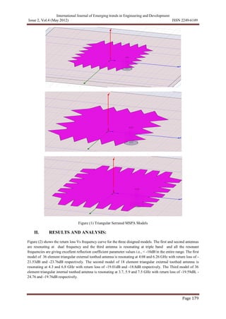
The present paper deals with different serrated models of triangular toothed antennas with different dimensions
and their performance comparison. For two models the serrated triangular tooth are at the external edges and for
one model the triangular tooth is inner side of the patch edge. External edged triangular patch antennas are
resonating at dual frequency and the inner edged triangular toothed patch antenna resonating at triple band.
Three models of the antennas are as shown in the figure (1).](https://image.slidesharecdn.com/ijeted-130620045557-phpapp01/85/Ijeted-1-320.jpg)
![International Journal of Emerging trends in Engineering and Development
Issue 2, Vol.4 (May 2012) ISSN 2249-6149
Page 178
Performance Investigation of Triangular
Toothed Serrated Microstrip Patch Antennas
1
B.T.P.Madhav, 1
VGKM Pisipati, 2
Anjaneyulu Badugu, 2
Y. Sudha Vani
1
LCRC-R&D, Department Of ECE, K L University, AP, India
2
Asst.Professor, ECE Department, Chebrolu Engineering College, Chebrolu, Guntur (D.T)
____________________________________________________________________________________________________
Abstract:
The performance characteristics of microstrip patch antennas depend on various factors like substrate material
selection, dimensions of the patch, substrate, feeding mechanism etc. This paper presents the performance
investigation on three types of triangular toothed serrated microstrip patch antennas. All these antennas are
having different patch dimensions, but having triangular tooth on its edges. The output parameters of all these
antennas are simulated using HFSS and the comparative analysis is presented in this paper. Among three
models, two models are resonating at dual frequency and one model is resonating at triple frequency.
Keywords: Triangular Tooth, Serrations, MSPA
____________________________________________________________________________________________________
Corresponding Author: B.T.P.Madhav
I. INTRODUCTION:
Microstrip antenna consists of a radiating patch and a ground plane on either side of a dielectric substance. The
patch is very thin and is usually made of conducting materials such as gold and copper. There are wide number
of substrates that can be used for the design of microstrip patch antenna. Thick substrates are desirable for
antenna performance. This type of substrates has dielectric constant in the lower end of the range. This is due to
larger bandwidth, better efficiency, and loosely bound fields for radiation into space but results in large element
size. With the increase in frequency, lower permittivity and thicker substrate, the radiation increases [1-3].
A good compromise has to be reached between circuit design and good antenna performance as microstrip
antennas are usually integrated with other microwave circuitry. Photo etching of feed lines and radiating
element is generally done on the dielectric substrate. The radiating patch may be of any configuration such as
square, dipole or thin strip, circular, rectangular, elliptical and triangular [4-6]. A microstrip antenna is made for
a broad range of resonant frequencies, impedance, polarization patterns and is very flexible. Microstrip antennas
have different feeding methods: Micro-strip line, coaxial-line feed and proximity coupled feed.
Microstrip antennas are widely used on mobile phones, laptops, microcomputers etc. These are also applicable
where narrow bandwidth is preferred such as in government security systems and mobile due to its operational
features like low power, low efficiency, poor polarization purity, poor scan performance, high quality factor,
narrow bandwidth. Circularly polarized microstrip antenna has wide applications in military. These are
mechanically robust. These antennas have few disadvantages such as low impedance bandwidth, low gain and
extra radiation at its feed and junctions. Size of microstrip antenna is sometimes an advantage or disadvantage
depending on the application [7-10].
The present paper deals with different serrated models of triangular toothed antennas with different dimensions
and their performance comparison. For two models the serrated triangular tooth are at the external edges and for
one model the triangular tooth is inner side of the patch edge. External edged triangular patch antennas are
resonating at dual frequency and the inner edged triangular toothed patch antenna resonating at triple band.
Three models of the antennas are as shown in the figure (1).](https://image.slidesharecdn.com/ijeted-130620045557-phpapp01/75/Ijeted-1-2048.jpg)
![International Journal of Emerging trends in Engineering and Development
Issue 2, Vol.4 (May 2012) ISSN 2249-6149
Page 180
2.00 3.00 4.00 5.00 6.00 7.00 8.00
Freq [GHz]
-25.00
-20.00
-15.00
-10.00
-5.00
0.00
dB(St(1,1))
Ansoft Corporation Patch_Antenna_ADKv1Return Loss
m 1
m 2
Curve Info
dB(St(1,1))
Setup1 : Sw eep1
Name X Y
m1 4.0829 -21.5376
m2 6.2688 -23.7656
Name Delta(X) Delta(Y) Slope(Y) InvSlope(Y)
d(m1,m2) 2.1859 -2.2280 -1.0192 -0.9811
2.00 3.00 4.00 5.00 6.00 7.00 8.00 9.00
Freq [GHz]
-20.00
-15.00
-10.00
-5.00
0.00
dB(St(1,1))
Ansoft Corporation Patch_Antenna_ADKv1Return Loss
m 1 m 2
Curve Info
dB(St(1,1))
Setup1 : Sw eep1
Name X Y
m1 4.3010 -19.0166
m2 6.8518 -18.8918
Name Delta(X) Delta(Y) Slope(Y) InvSlope(Y)
d(m1,m2) 2.5508 0.1248 0.0489 20.4381
2.00 3.00 4.00 5.00 6.00 7.00 8.00 9.00
Freq [GHz]
-25.00
-20.00
-15.00
-10.00
-5.00
0.00
dB(St(1,1))
Ansoft Corporation Patch_Antenna_ADKv1Return Loss
m 1
m 2
m 3
Curve Info
dB(St(1,1))
Setup1 : Sw eep1
Name X Y
m1 3.7854 -19.5958
m2 5.9563 -24.7679
m3 7.5573 -19.7625
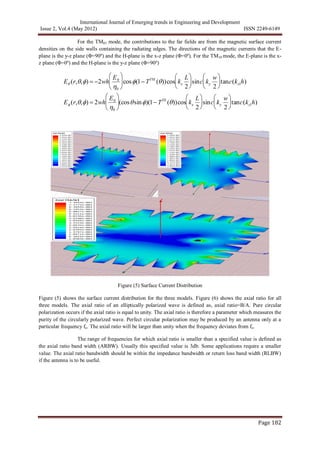
Figure (2) Return Loss Vs Frequency
5.002.001.000.500.20
5.00
-5.00
2.00
-2.00
1.00
-1.00
0.50
-0.50
0.20
-0.20
0.00-0.00
0
10
20
30
40
50
60
70
8090100
110
120
130
140
150
160
170
180
-170
-160
-150
-140
-130
-120
-110
-100 -90 -80
-70
-60
-50
-40
-30
-20
-10
Ansoft Corporation Patch_Antenna_ADKv1Input Impedance
Curve Info bandw idth(1, 0)
St(1,1))
Setup1 : Sw eep1
3.7466
5.002.001.000.500.20
5.00
-5.00
2.00
-2.00
1.00
-1.00
0.50
-0.50
0.20
-0.20
0.00-0.00
0
10
20
30
40
50
60
70
8090100
110
120
130
140
150
160
170
180
-170
-160
-150
-140
-130
-120
-110
-100 -90 -80
-70
-60
-50
-40
-30
-20
-10
Ansoft Corporation Patch_Antenna_ADKv1Input Impedance
Curve Info bandw idth(1, 0)
St(1,1))
Setup1 : Sw eep1
3.9505
5.002.001.000.500.20
5.00
-5.00
2.00
-2.00
1.00
-1.00
0.50
-0.50
0.20
-0.20
0.00-0.00
0
10
20
30
40
50
60
70
8090100
110
120
130
140
150
160
170
180
-170
-160
-150
-140
-130
-120
-110
-100 -90 -80
-70
-60
-50
-40
-30
-20
-10
Ansoft Corporation Patch_Antenna_ADKv1Input Impedance
Curve Info bandw idth(1, 0)
St(1,1))
Setup1 : Sw eep1
3.5711
Figure (3) Input Impedance Smith Chart
Figure (3) shows the input impedance smith chart for all the three models of serrated triangular toothed
antennas. The input impedance at the feed of the antenna is
Z = R+jX =
V
I
Eavt
I](https://image.slidesharecdn.com/ijeted-130620045557-phpapp01/85/Ijeted-3-320.jpg)
![International Journal of Emerging trends in Engineering and Development
Issue 2, Vol.4 (May 2012) ISSN 2249-6149
Page 183
Figure (6) Axial Ratio
III. CONCLUSION:
All the three models are showing excellent and moderate results for the applicability of these antennas in dual
and triple band applications. First model is resonating at dual band with gain of 7.0127dB, peak directivity of
5.0722, radiated power of 0.00085238 and radiation efficiency of 0.991. The second model is also resonating at
dual mode with gain of 6.5074dB, peak directivity of 4.5471, radiated power of 0.00073617 and radiation
efficiency of 0.985. The third model is resonating at triple band with gain of 7.72dB, peak directivity of 6.01,
radiated power 0.0012922 and radiation efficiency of 0.984. Overall the third model is giving better gain and
radiated power compared to other models. The second model is showing lesser performance characteristics
compared to other models but radiation efficiency is better than third model. The performance characteristics by
changing the dimensions of the patch with respect to serrations are analyzed and presented in this work.
ACKNOWLEDGMENTS
The authors B.T.P.Madhav, Prof. VGKM Pisipati and T.V.Ramakrishna express their thanks to the management
of K L University and Department of Electronics and Communication Engineering for their support. Further,
VGKM Pisipati acknowledges the financial support of Department of Science and Technology through the grant
No.SR/S2/CMP-0071/2008.
REFERENCES
[1] K. L. Wong and J. Y. Sze, “Dual-frequency slotted rectangular microstrip antenna,” Electron. Lett. 34,
1368–1370, July 9, 1998.
[2] J. H. Lu, “Single-feed dual-frequency rectangular microstrip antenna with pair of step-slots,” Electron. Lett.
35, 354–355, March 4, 1999.
[3] K. S. Kim, T. Kim, and J. Choi, “Dual-frequency aperture-coupled square patch antenna with double
notches,” Microwave Opt. Technol. Lett. 24, 370–374, March 20, 2000.](https://image.slidesharecdn.com/ijeted-130620045557-phpapp01/85/Ijeted-6-320.jpg)
![International Journal of Emerging trends in Engineering and Development
Issue 2, Vol.4 (May 2012) ISSN 2249-6149
Page 184
[4] C. C. Huang, Dual-frequency microstrip arrays with a dual-frequency feed network, M.S. thesis, Department
of Electrical Engineering, National Sun Yat-Sen University, Kaohsiung, Taiwan, 2000.
[5] S. T. Fang and K. L. Wong, “A dual-frequency equilateral-triangular microstrip antenna with a pair of
narrow slots,” Microwave Opt. Technol. Lett. 23, 82–84, Oct. 20, 1999.
[6] K. P. Yang, Studies of compact dual-frequency microstrip antennas, Ph.D. dissertation, Department of
Electrical Engineering, National Sun Yat-Sen University, Kaohsiung, Taiwan, 1999.
[7] J. H. Lu and K. L. Wong, “Compact dual-frequency circular microstrip antenna with an offset circular slot,”
Microwave Opt. Technol. Lett. 22, 254–256, Aug. 20, 1999.
[8] W. P. Dou and Y. W. M. Chia, “Novel meandered planar inverted-F antenna for triple-frequency operation,”
Microwave Opt. Technol. Lett. 27, 58–60, Oct. 5, 2000.
[9] G. S. Row, S. H. Yeh, and K. L. Wong, “Compact dual-polarized microstrip antennas,” Microwave Opt.
Technol. Lett. 27, 284–287, Nov. 20, 2000.
[10] T. W. Chiou and K. L. Wong, “Designs of compact microstrip antennas with a slotted ground plane,” in
2001 IEEE Antennas Propagat. Soc. Int. Symp. Dig., pp. 732–735.
Authors Biography:
B.T.P.Madhav was born in India, A.P, in 1981. He received the B.Sc, M.Sc, MBA, M.Tech degrees from Nagarjuna
University, A.P, India in 2001, 2003, 2007, and 2009 respectively. From 2003-2007 he worked as lecturer and from 2007 to
till date he is working as Associate Professor in Electronics Engineering. He has published more than 80 papers in
International and National journals. His research interests include antennas, liquid crystals applications and wireless
communications.
Prof. VGKM Pisipati was born in India, A.P, in 1944. He received his B.Sc, M.Sc and PhD degrees from Andhra
University. Since 1975 he has been with physics department at Acharya Nagarjuna University as Professor, Head, R&D
Director. He guided 22 PhDs and more than 20 M.Phils. His area of research includes liquid crystals, nanotechnology and
liquid crystals applications. He visited so many countries and he is having more than 320 International research publications.
He served different positions as academician and successfully completed different projects sponsored by different
government and non-government bodies. He is having 5 patents to his credit.
Anjaneyulu Badugu was born in India.in 1987. He did his B.Tech under JNTU and M.Tech from K L
University. Presently he is working as Asst.Professor in ECE Department of Chebrolu Engineering College. His research
Interests includes Antennas and Digital Communication.](https://image.slidesharecdn.com/ijeted-130620045557-phpapp01/85/Ijeted-7-320.jpg)

The document summarizes the performance investigation of three types of triangular toothed serrated microstrip patch antennas. The first and second antenna models have triangular teeth on the external edges and resonate at dual frequencies. The third model has triangular teeth on the inner edges and resonates at triple frequencies. Simulation results show the first model resonates at 4.08 GHz and 6.26 GHz, the second at 4.3 GHz and 6.8 GHz, and the third at 3.7 GHz, 5.9 GHz, and 7.5 GHz. Input impedance and radiation patterns are also analyzed, with the third model showing slightly better bandwidth performance.


![Communication Systems.pdfgda[galgalglg]sa;g](https://cdn.slidesharecdn.com/ss_thumbnails/communicationsystems-240907054847-16a79cd5-thumbnail.jpg?width=640&height=640&fit=bounds)


