Download to read offline

![International Journal of Antennas (JANT) Vol.7, No.1, January 2021
2
2. THEORIES
2.1. Microstrip Antenna
Microstrip antennas are electrically thin, lightweight, comformable, low cost, easily fabricated
and can be connected to Microwave Integrated Circuits (MICs) at various frequencies [1]. There
are various types of microstrip antenna designs on the taper section. There is a rectangular,
circular, triangle shape according to the empirical analysis of antenna design. The design of the
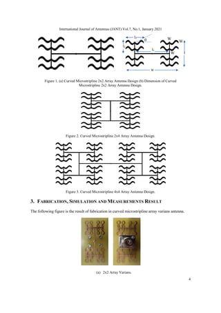
antennas varies with the single side and the double side. This study designed novel curved
microstripline antenna with 2x2, 2x4 and 4x4 array, to produce greater gain so that it could be
more optimally applied to radar communication systems.
2.2. Array Factor
Microstrip antennas arranged in Array are not only useful for widening bandwidth but also have
an impact on the radiation pattern produced. The radiation pattern in the Antenna is generally
written with the equation:
𝑅 (𝜃, ∅) with i element in the position of 𝑟𝑖 = (𝑥𝑖, 𝑦𝑖,𝑍𝑖)
The relationship with the wave emitted from the antenna array (Y) with the multiplier of complex
numbers (wi) in the function (θ, ∅), is obtained:
𝑌 = 𝑅 (𝜃, ∅)𝑤1𝑒−𝑗 𝑘 . 𝑟1 + 𝑅 (𝜃, ∅)𝑤2𝑒−𝑗 𝑘.𝑟2 + ⋯ 𝑅(𝜃, ∅)𝑤𝑁𝑒−𝑗 𝑘 𝑟𝑁
With k is the wave vector in the incoming wave.
Next can be written:
𝑌 = 𝑅 (𝜃, ∅) ∑ 𝑤𝑖𝑒−𝑗 𝑘 .𝑟𝑖
𝑁
𝑖=1
𝑌 = (𝜃, ∅) 𝐴𝐹
; 𝐴𝐹 = ∑ 𝑤𝑖𝑒−𝑗 𝑘 .𝑟𝑖
𝑁
𝑖=1
AF = Array Factor (as an Antenna position function).
2.3. Design Overview
Calculation of Antenna Dimensions uses the following steps:
The first calculating is to find the total electricity permittivity (εrtot) using the capacitor equation:
2
1
tot c
1
c
1
c
1
](https://image.slidesharecdn.com/7121jant01-221027040241-e5429def/85/ARRAY-FACTOR-IN-CURVED-MICROSTRIPLINE-ARRAY-ANTENNA-FOR-RADAR-COMMUNICATION-SYSTEMS-2-320.jpg)

![International Journal of Antennas (JANT) Vol.7, No.1, January 2021
13
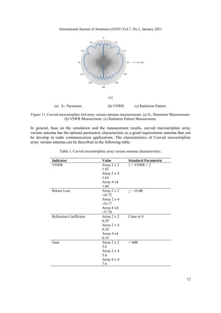
4. CONCLUSION
Adding Arrays to the Curved Microstripline Antenna gives more optimal results especially in the
range of working frequencies (bandwidth) and also the resulting gain. The results indicate that the
antenna is able to apply in multiband frequency. The radiation pattern produced in this design is
Omnidirectional in linear polarization. The band frequencies array in this design is capable to
develope in radar application communication systems.
ACKNOWLEDGMENT
The authors would like to thank the Indonesian Ministry of Research, Technology and Higher
Education through LPDP and PKPI (Sandwich-like) scholarships, Center for Environmental
Remote Sensing (CEReS), Josaphat Tetuko Sri Sumantyo (JMRSL Chiba University), Promotor
Yono Hadi Pramono and Mashuri (Physics Department, ITS Surabaya), and Ganesha University
of Education (Undiksha), Singaraja Bali.
REFERENCES
[1] Artawan. Fabrikasi dan Karakterisasi Antena Mikrostrip Tapered Patch Untuk Aplikasi Antena Panel
Pada Frekuensi 2,4GHz. Tesis Magister, Jurusan Fisika, Fakultas Matematika dan Ilmu Pengetahuan
Alam, Institut Teknologi Sepuluh Nopember (ITS), Surabaya, 2011.
[2] Artawan, Hadi Pramono, Yono. Perancangan Antena Panel Mikrostrip Horn Array 2x2 Untuk
Komunikasi Wi-Fi Pada Frekuensi 2,4GHz. Prosiding Simposium Fisika Nasional (SFN), ITS,
Surabaya, 2010.
[3] Balanis, C.A. Antena Theory Analysis and Design. Second Edition, John Wiley and Sons, New York,
1997.
[4] Edward, Terry. Foundation For Microstrip Circuit Design. Knaresborough England, 1991.
[5] Shafai. Microstrip Antena Design Handbook. Profesor University Of Manitoba, Wimmipeg, Canada,
2001.
[6] Kraus, John, D. Electromagnetics. Third Edition, McGraw-Hill, New York, 1984.
[7] Ohri, V, Amin, O, Gebremariam, H Dubois, B. Microwave Mikrostrip Horn Antena Design and Test
System. San Jose State University, 2003.
[8] Masduki, K. Desain, Fabrikasi dan Karakterisasi Antena Mikrostrip Biquad dengan CPW (Coplanar
Waveguide) pada Frekuensi Kerja 2,4GHz. Program Magister Bidang Keahlian Optoelektronika
Jurusan Fisika, FMIPA-ITS: Surabaya. 2009.
[9] Hund, E. Microwave Communications, Component and Circuit. McGraw Hill, New York, 1989.
[10] Hadi Pramono, Yono. Karakterisasi Antena Mikrostip Patch 3GHz Secara Simulasi FDTD (Finite
Difference Time Domain) Dan Eksperimen. Jurnal Fisika. Institut Teknologi Sepuluh Nopember.
Surabaya, 2005.
[11] Hadi Pramono, Yono. Prototipe Antenna Bi-Mikrostrip Tapered Patch dengan Dua Arah Pola Radiasi
Dan Satu Feeding Monopole Beroperasi Pada Freq.2,4GHz. Prosiding T. Informatika, UPN.
Yogyakarta, 2009.](https://image.slidesharecdn.com/7121jant01-221027040241-e5429def/85/ARRAY-FACTOR-IN-CURVED-MICROSTRIPLINE-ARRAY-ANTENNA-FOR-RADAR-COMMUNICATION-SYSTEMS-13-320.jpg)
![International Journal of Antennas (JANT) Vol.7, No.1, January 2021
14
[12] Hidayah, Ifa. Desain dan Fabrikasi Antena Bi-Mikrostrip Tapered Patch dengan Dua Arah Radiasi
dan Satu Feeding Monopole Untuk Komunikasi Wi-fi. Tesis Magister. Institut Tekologi Sepuluh
Nopember. Surabaya, 2009.
[13] Naqiah, Hawaun. Fabrikasi dan Karakterisasi Antena Mikrostrip Loopline untuk Komunikasi
Wireless Local Area Network (WLAN). Program Magister Bidang Keahlian Optoelektronika Jurusan
Fisika FMIPA-ITS: Surabaya, 2009.
[14] Risfaula, Erna. Antena Mikrostrip Panel Berisi 5 Larik Dipole dengan Feedline Koaksial Waveguide
untuk Komunikasi 2,4GHz. Program Keahlian Optoelektronika Jurusan fisika FMIPA-ITS: Surabaya,
2011.
[15] S. Gao, Q. Luo, F. Zhu, Circularly Polarized Antenna, John Wiley & Sons, Ltd, 2014.
[16] S. Murugan, V. Rajamani, “Study of Broadband Circularly Polarised Microstrip Antenna” Science
Engineering and Management Research (ICSEMR), 2014 International Conference on. IEEE, 2014.
[17] Haider Raad, “An UWB Antenna Array for Flexible IoT Wireless System,” Progress In
Electromagnetics Research, Vol. 162, 109-121, 2018.
[18] Kurniawan Farohaji, Sri Sumantyo, J. T, Gao Steven, Ito Koichi, Edi Santosa C. “Square-Shaped
Feeding Truncated Circularly Polarised Slot Antenna”. IET Microwaves, Antenna & Propagation
Journals. ISSN 1751-8725, 2018.
[19] Edi Santosa C, Sri Sumantyo, J.T, Yam Chua Ming, Urata Katia, Ito Koichi, Gao Steven. “Subarray
Design for C-Band Circularly-Polarized Synthetic Aperture Radar Antenna Onboard Airborne,”
Progress In Electromagnetics Research, Vol. 163, 107-117, 2018.
[20] Xu Mao-Chun, Gao Steven, Wang Yi, Sri Sumantyo, J.T. “Compact Broadband Dual-Sense
Circularly Polarized Microstrip Antenna/Array With Enhanced Isolation”. IEEE Transactions on
Antennas And Propagation, Vol 65, No.12, 2017.
[21] Luo Qi, Gao Steven, Sobhy Mohammed, Sri Sumantyo, J.T, Li Jianzhou, Wei Gao, Xu Jiadong, Wu
Changying. “Dual Circularly Polarised Equilateral Triangular Patch Array”. IEEE Transactions on
Antennas And Propagation, Vol 64, No.6, 2016.
[22] Kumar Dwivedi M, Srivastava Pragati. “Microstrip Patch Array Antenna for X-Band Application”.
Antenna Test and Measurement Society (ATMS India-16), 01-03 Feb, 2016.](https://image.slidesharecdn.com/7121jant01-221027040241-e5429def/85/ARRAY-FACTOR-IN-CURVED-MICROSTRIPLINE-ARRAY-ANTENNA-FOR-RADAR-COMMUNICATION-SYSTEMS-14-320.jpg)

Dokumen ini membahas desain antena array pada mikrostrip melengkung untuk sistem komunikasi radar, mencakup geometri antena variasi 2x2, 2x4, dan 4x4 yang beroperasi dalam frekuensi C-band dan X-band. Hasil menunjukan karakteristik parametris yang optimal dengan pengukuran yang mendukung, menunjukkan kemampuan antena untuk pengembangan aplikasi komunikasi radar. Penelitian ini menekankan pentingnya efisiensi ukuran, berat, dan konsumsi daya antena dalam aplikasinya.


