Download to read offline
![International Journal of Electronics and Communication Engineering & Technology (IJECET), ISSN 0976 –
6464(Print), ISSN 0976 – 6472(Online), Volume 5, Issue 2, February (2014), pp. 98-102 © IAEME
98
TWO ELEMENT U - SLOT LOADED CIRCULAR MICROSTRIP ARRAY
ANTENNA FOR WLAN APPLICATIONS
Dr. Nagraj K. Kulkarni
Government College, Gulbarga-585105, Karkataka, India
ABSTRACT
This paper presents the two element U- slot loaded circular microstrip array antenna for dual
band operation. The antenna operates between 2.6 to 7.00 GHz. The antenna has been fabricated
with a volume of 9 X 5 X 0.16 cm3
. The maximum bandwidth of 44.90% is achieved. With a peak
gain of 5.24 dB is obtained in primary band. The antenna exhibits a broadside and linear radiation
characteristics. The results are presented and discussed. This antenna may find its applications in
WLAN communication system.
Keywords: Two Element, Circular, Microstrip Antenna, Size Reduction.
1. INTRODUCTION
In today’s era microstrip antennas (MSAs) have become the attractive candidate for the
antenna designers because of their inherent features such as light weight, low profile, compatibility
with MMICs [1] etc. The patch antennas are receiving increasing interest in modern communication
systems such as WLAN, WiMAX, HIPERLAN/2 etc, because of their many advantages over
traditional microwave antennas in terms of achieving dual, triple and multiple bands which are
realized by using different techniques such as, cutting slots of different geometries like rectangular,
L- shape, E-shape, circular shape, square shape [2-7] etc. In many applications, the wide bandwidth
and gain are the essential needs to use the antenna for specific applications. During past years, many
efforts have been put forth to realize bandwidth widening techniques of microstrip antennas, which
include the use of impedance matching, multiple resonators and a thick substrate [8, 9] etc. But, the
two element array antenna having a U shaped slots on the circular radiating patch and plus shaped
slots on the ground plane is used for enhancing the bandwidth and gain. This kind of study is found
to be rare in the literature. The slot loading technique provides the freedom to design the required
slot irrespective of their size or shape and can be suitably loaded at the desired place on the geometry
of the antenna for broadening the bandwidth of the antenna [9]. Also, the array technique, gives the
INTERNATIONAL JOURNAL OF ELECTRONICS AND
COMMUNICATION ENGINEERING & TECHNOLOGY (IJECET)
ISSN 0976 – 6464(Print)
ISSN 0976 – 6472(Online)
Volume 5, Issue 2, February (2014), pp. 98-102
© IAEME: www.iaeme.com/ijecet.asp
Journal Impact Factor (2014): 7.2836 (Calculated by GISI)
www.jifactor.com
IJECET
© I A E M E](https://image.slidesharecdn.com/40120140502013-140325094955-phpapp01/85/40120140502013-1-320.jpg)
![International Journal of Electronics and Communication Engineering & Technology (IJECET), ISSN 0976 –
6464(Print), ISSN 0976 – 6472(Online), Volume 5, Issue 2, February (2014), pp. 98-102 © IAEME
99
flexibility to design the required feed line between the array elements to energize, which helps in
enhancing the gain of the antenna [10].
2. DESIGN AND EXPERIMENTAL RESULTS
The antenna is fabricated using low-cost glass epoxy substrate material of thickness h = 1.6
mm and dielectric constant εr = 4.2. Artwork of the antenna is sketched using computer software
Auto-CAD 2006 to achieve better accuracy. The antenna is etched using photolithography process.
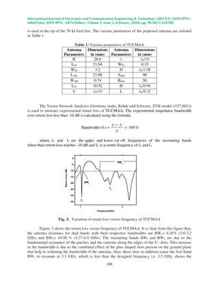
Fig. 1: Top view Geometry of TUCMAA
Figure 1 shows the top view geometry of the two element, U-slot loaded circular microstrip
array antenna(TUCMAA). The antenna has two circular patches of radius R are designed for the
resonant frequency of 3.5 GHz, using the basic equations available in the literature. The U shaped
slot of horizontal and vertical arm lengths h and v are placed on the two circular patches.
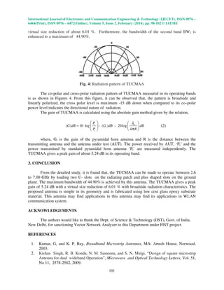
Fig. 2: Bottom view Geometry of TUCMAA
Fig. 2 shows the bottom view geometry of TUCMAA. The two plus shaped slots which are D
mm apart and each having a width 2 mm are incorporated on the ground plane such that the mid-
point of these slots lie exactly below the center of the each radiating patch. The L and H are the
horizontal and vertical arm lengths of the plus shaped slots. The dimensions D, R h, v, L and H are
taken in terms of λ0, where λ0 is the free space wavelength in millimeter corresponding to the
designed frequency of 3.5 GHz. The parallel feed arrangement is used in the present study, because
it has the advantage over series fed arrangement, that is, its wideband performance. The feed
arrangement shown in this figure is a contact feed and has the advantage that it can be etched
simultaneously along with the antenna elements. The microstripline feed arrangement is designed
using the relations available in the literature [12]. A 50 feed line of length L50 and width W50 is
connected to 100 line of length L100 and width W100 to form a two way power divider. A quarter
wave transformer of length Ltr and width Wtr is connected between 100 feed line and midpoint of
the radiating elements to establish perfect impedance matching. A 50 semi miniature–A connector](https://image.slidesharecdn.com/40120140502013-140325094955-phpapp01/85/40120140502013-2-320.jpg)


This document summarizes a research paper on a two element U-slot loaded circular microstrip array antenna designed for dual band wireless local area network (WLAN) applications. The antenna was fabricated on a glass epoxy substrate measuring 9 x 5 x 0.16 cm3. Testing showed it achieved a maximum bandwidth of 44.9% between 4.37-6.9 GHz and was able to reduce the size of the antenna by 6.01% while maintaining a peak gain of 5.24 dB. Analysis of the radiation patterns found it exhibited broadside and linearly polarized radiation characteristics. The proposed antenna design was concluded to be simple, low-cost, and suitable for WLAN communication systems.